Given the data structures defining the buttons, this code in the main loop() detects a touch, identifies the corresponding button, and does what’s needed:
if (CleanTouch(&pt)) {
	BID = FindHit(pt);
	if (BID) {
		HitButton(BID);
	}
	while(ts.touched())				// stall waiting for release
		ts.getPoint();
}
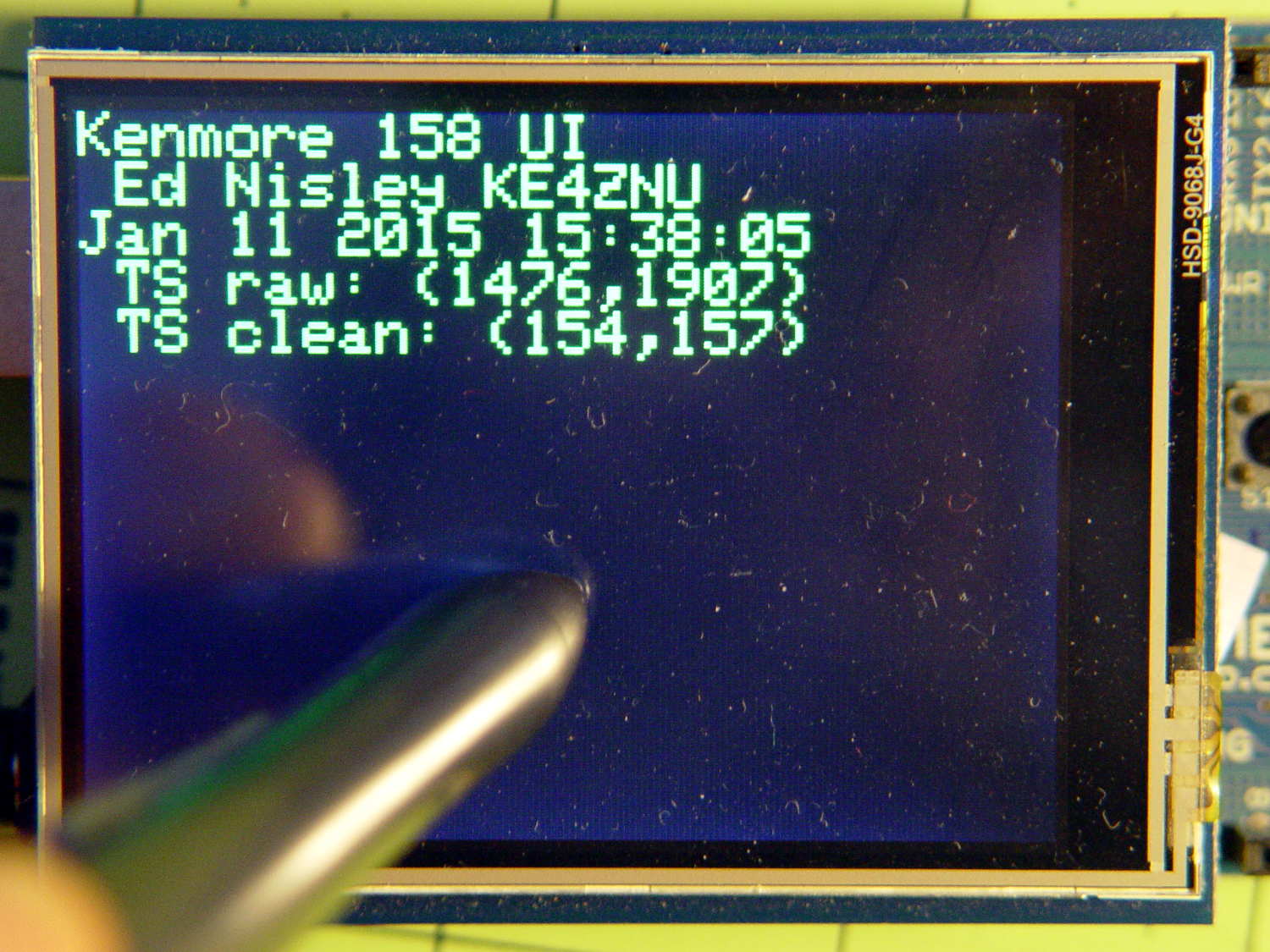
The CleanTouch() function handles touch detection, cleanup, and rotation, delivering a coordinate that matches one of the LCD pixels. Given that you’re using a fingertip, errors caused by poor calibration or nonlinearities Just Don’t Matter.
This function matches that coordinate against the target region of each button, draws a white rectangle on the first matching button, and returns that button ID:
byte FindHit(TS_Point hit) {

byte i;
TS_Point ul,lr;

#define MARGIN 12

//	printf("Hit test: (%d,%d)\r\n",hit.x,hit.y);

	for (i=0; i<NumButtons ; i++) {
		ul.x = Buttons[i].ulX + Buttons[i].szX/MARGIN;
		ul.y = Buttons[i].ulY + Buttons[i].szY/MARGIN;
		lr.x = Buttons[i].ulX + ((MARGIN - 1)*Buttons[i].szX)/MARGIN;
		lr.y = Buttons[i].ulY + ((MARGIN - 1)*Buttons[i].szY)/MARGIN;
//		printf(" i: %d BID: %d S: %d ul=(%d,%d) sz=(%d,%d)\r\n",
//			   i,Buttons[i].ID,Buttons[i].Status,ul.x,ul.y,lr.x,lr.y);
		if ((hit.x >= ul.x && hit.x < lr.x) &&
			(hit.y >= ul.y && hit.y <= lr.y)) {
			// should test for being disabled and discard hit
//			printf(" Hit i: %d ",i);
			break;
		}
	}

	if (i < NumButtons) {
		tft.drawRect(ul.x,ul.y,lr.x-ul.x,lr.y-ul.y,ILI9341_WHITE);
		return Buttons[i].ID;
	}
	else {
		printf(" No hit!\r\n");
		return 0;
	}

}
You can enable as much debugging as you need by fiddling with the commented-out lines.
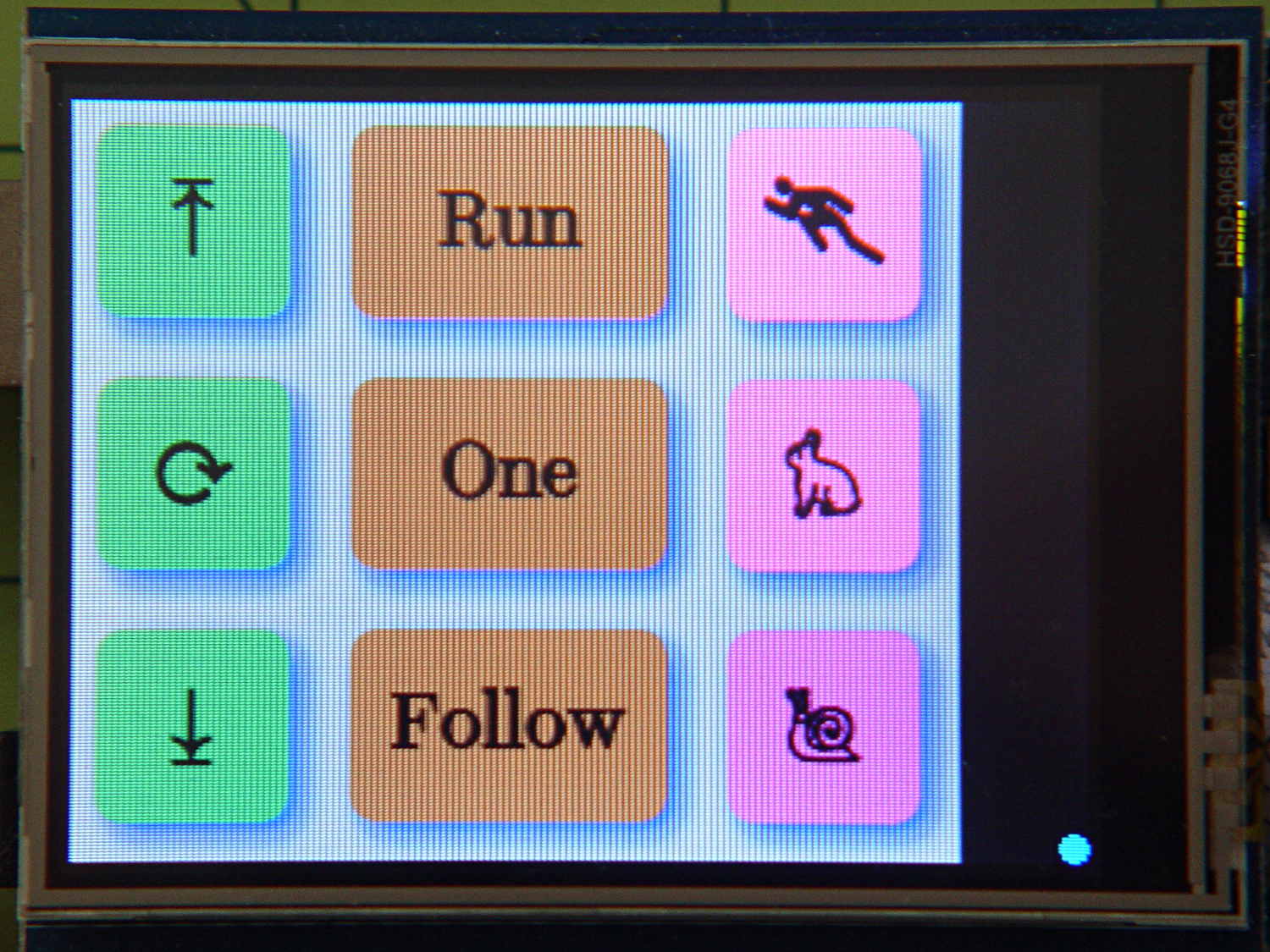
After some empirical fiddling, a non-sensitive margin of 1/12 the button size helped prevent bogus hits. There’s no real need to draw the target rectangle, other than for debugging:
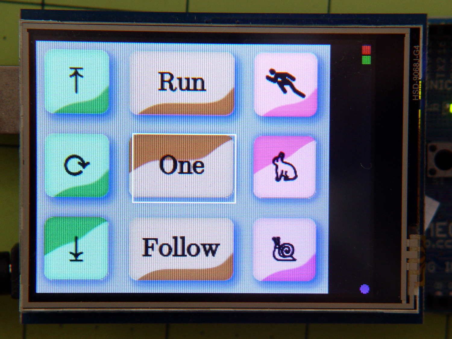
The target shows the button graphics aren’t quite centered, because that’s how the ImageMagick script placed them while generating the shadow effect, but it still works surprisingly well. The next version of the buttons will center the graphics, specifically so I don’t have to explain what’s going on.
Because the margin is 1/12 the size of the button, it rounds off to zero for the tiny button in the upper right corner, so that the touch target includes the entire graphic.
The return value will be zero if the touch missed all the buttons, which is why a button ID can’t be zero.
Given the button ID, this function un-pushes the other button(s) in its radio button group, then pushes the new button:
byte HitButton(byte BID) {

byte i,BX;
byte Group;

	if (!BID)											// not a valid ID
		return 0;

	BX = FindButtonIndex(BID);
	if (BX == NumButtons)								// no button for that ID
		return 0;

	Group = Buttons[BX].Group;

//	printf(" Press %d X: %d G: %d\r\n",BID,BX,Group);

// If in button group, un-push other buttons

	if (Group) {
		for (i=0; i<NumButtons; i++) {
			if ((Group == Buttons[i].Group) && (BT_DOWN == Buttons[i].Status)) {
				if (i == BX) {							// it's already down, fake going up
					Buttons[i].Status = BT_UP;
				}
				else {									// un-push other down button(s)
//					printf(" unpress %d X: %d \r\n",Buttons[i].ID);
					Buttons[i].pAction(Buttons[i].ID);
				}
			}
		}
	}

	Buttons[BX].pAction(BID);

	return 1;
}
The ID validation shouldn’t be necessary, but you know how things go. A few messages in there would help debugging.
The default button action routine that I use for all the buttons just toggles the button’s Status and draws the new button graphic:
void DefaultAction(byte BID) {

byte i,BX;

	if (!BID) {											// not a valid ID
		printf("** Button ID zero in DefaultAction\r\n");
		return;
	}

	BX = FindButtonIndex(BID);
	if (BX == NumButtons) {								// no button for that ID
		printf("** No table entry for ID: %d\r\n",BID);
		return;
	}

	Buttons[BX].Status = (Buttons[BX].Status == BT_DOWN) ? BT_UP : BT_DOWN;

	printf("Button %d hit, now %d\r\n",BID,Buttons[BX].Status);
	DrawButton(BID,Buttons[BX].Status);

}
The little color indicator button has a slightly different routine to maintain a simple counter stepping through all ten resistor color codes in sequence:
void CountColor(byte BID) {

byte i,BX;
static byte Count = 0;

	if (!BID) {											// not a valid ID
		printf("** Zero button ID\r\n");
		return;
	}

	BX = FindButtonIndex(BID);
	if (BX == NumButtons) {								// no button for that ID
		printf("** No entry for ID: %d\r\n",BID);
		return;
	}

	Buttons[BX].Status = BT_DOWN;						// this is always pressed

	Count = (Count < 9) ? ++Count : 0;					// bump counter & wrap

//	printf("Indicator %d hit, now %d\r\n",BID,Count);
	DrawButton(BID,Count);

}
The indicator “button” doesn’t go up when pressed and its function controls what’s displayed.
I think the button action function should have an additional parameter giving the next Status value, so that it knows what’s going on, thus eliminating the need to pre-push & redraw buttons in HitButton(), which really shouldn’t peer inside the button data.
It needs more work and will definitely change, but this gets things started.