Because the universal-wound AC motor runs on DC, it will also run on full-wave rectified AC (top trace). The current waveform (bottom, 200 mA/div) never hits zero:
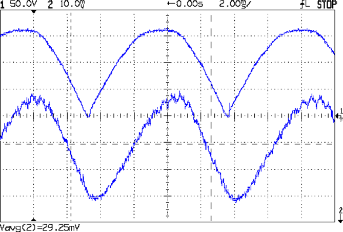
Note that the current lags the voltage, as you’d expect from an inductive load.
The average current at 120 VAC rectified is about 600 mA, a bit over the current at 50 V that I measured from the DC supply while driving the sewing machine. The locked-rotor torque averages 1 A, although it’s pretty hard to hold the handwheel at full voltage.
The key advantage of rectified AC: an ordinary MOSFET can control the motor current.
Given the motor’s sensitivity to current limiting, there’s not much point in measuring the current; unlike LED brightness, the speed isn’t proportional to the current. The MOSFET must act more like the carbon pile rheostat, burning whatever voltage the motor doesn’t need to run at the selected speed, with the RPM setpoint determining the gate voltage in a closed loop.
You can detect a stall by watching the motor RPM: when that drops too far below the setpoint, it’s stalled.
The gotcha will be keeping the MOSFET within its the safe operating area at both ends of the voltage range, due to the nearly constant current at any applied voltage:
- High voltage + high current hits the maximum pulsed power limit of IDSVDS
- Low voltage + high current hits the minimum possible voltage of IDSRDS
I think the relatively low current and power levels will simplify that mess; offering up a sacrificial MOSFET for measurement may be in order.
On the whole, it’s looking more do-able than I thought.

Comments
6 responses to “Kenmore 158: Rectified AC Current”
That MOSFET will need a serious heat sink a d fan, no?
You betcha!
Figuring that the motor draws half an amp, the MOSFET must burn 50 W at low speeds. That’s right on the hairy edge of what a TO-220 package can handle: it’s definitely a brute force application. Worse, the MOSFET operates way over on the right side of the SOA plot, where high voltage combined with high current normally requires low duty cycles and leads to thermal runaway in linear mode.
The only redeeming feature: no acoustic noise from PWM or current chopping. A high-volume, low-speed fan on a mighty heatsink will definitely be in order…
Hi Ed,
You could also try to put the mosfet in the middle of a rectfier bridge.
Then you can control AC with a single mosfet.
Maybe pwm will work.
I may yet stir an isolation transformer into this mess, which would both simplify the gate drive and keep me from inadvertently frying myself…
Have you considered driving the mosfet with PWM at a frequency that is higher than 20KHz and incorporating an LC filter between the switch and the motor. There would not need to be any feedback and the losses in the mosfet would be much lower.
Well, she can hear things I can’t, including stepper drives that should be inaudible to everybody, so I’m leery of rash assumptions concerning frequencies. [grin]
At this point, I’m still poking the problem with a sharp stick to get some idea of how big it is; even if I don’t like PWM, the solution may look a lot like that.