Ed Nisley's Blog: Shop notes, electronics, firmware, machinery, 3D printing, laser cuttery, and curiosities. Contents: 100% human thinking, 0% AI slop.
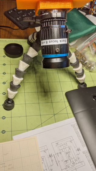
Part of the motivation for getting a Raspberry Pi HQ camera sensor was being able to use lenses with adjustable focus and aperture, like the Official 10 MP “telephoto” lens:
RPi HQ Camera – aperture demo setup
Yes, it can focus absurdly close to the lens, particularly when you mess around with the back focus adjustment.
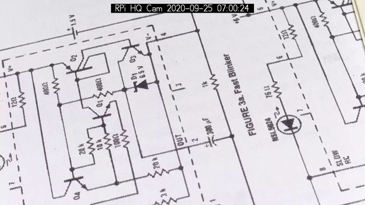
With the aperture fully open at f/1.4:
RPi HQ Camera – aperture demo – f 1.4
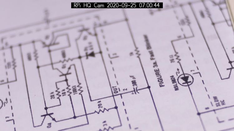
Stopped down to f/16:
RPi HQ Camera – aperture demo – f 16
The field of view is about 60 mm (left-to-right) at 150 mm. Obviously, arranging the camera with its optical axis more-or-less perpendicular to the page will improve everything about the image.
For normal subjects at normal ranges with normal lighting, the depth of field works pretty much the way you’d expect:
At f/1.4, focused on the potted plants a dozen feet away:
Raspberry Pi HQ Camera – outdoor near focus
Also at f/1.4, focused on the background at infinity:
Raspberry Pi HQ Camera – outdoor far focus
In comparison, the laptop camera renders everything equally badly (at a lower resolution, so it’s not a fair comparison):
None of this is surprising, but it’s a relief from the usual phone sensor camera with fixed focus (at “infinity” if you’re lucky) and a wide-open aperture.
Rummaging through the Big Box o’ Optics in search of something else produced this doodad:
Microscope objective illuminator – overview
It carries no brand name or identifier, suggesting it was shop-made for a very specific and completely unknown purpose. The 5× objective also came from the BBo’O, but wasn’t related in any way other than fitting the threads, so the original purpose probably didn’t include it.
The little bulb fit into a cute and obviously heat-stressed socket:
Microscope objective illuminator – bulb detail
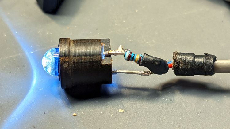
The filament was, of course, broken, so I dismantled the socket and conjured a quick-n-dirty white LED that appears blue under the warm-white bench lighting:
Microscope objective illuminator – white LED
The socket fits into the housing on the left, which screws onto a fitting I would have sworn was glued / frozen in place. Eventually, I found a slotted grub screw hidden under a glob of dirt:
Microscope objective illuminator – lock screw
Releasing the screw let the fitting slide right out:
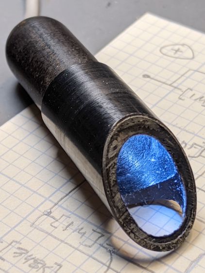
Microscope objective illuminator – lamp reflector
The glass reflector sits at 45° to direct the light coaxially down into the objective (or whatever optics it was originally intended for), with the other end of the widget having a clear view straight through. I cleaned the usual collection of fuzz & dirt off the glass, then centered and aligned the reflection with the objective.
Unfortunately, the objective lens lacks antireflection coatings:
Microscope objective illuminator – stray light
The LED tube is off to the right at 2 o’clock, with the bar across the reflector coming from stray light bouncing back from the far wall of the interior. The brilliant dot in the middle comes from light reflected off the various surfaces inside the objective.
An unimpeachable source tells me microscope objectives are designed to form a real image 180 mm up inside the ‘scope tube with the lens at the design height above the object. I have the luxury of being able to ignore all that, so I perched a lensless Raspberry Pi V1 camera on a short brass tube and affixed it to a three-axis positioner:
Microscope objective illuminator – RPi camera lashup
A closer look at the lashup reveals the utter crudity:
Microscope objective illuminator – RPi camera lashup – detail
It’s better than I expected:
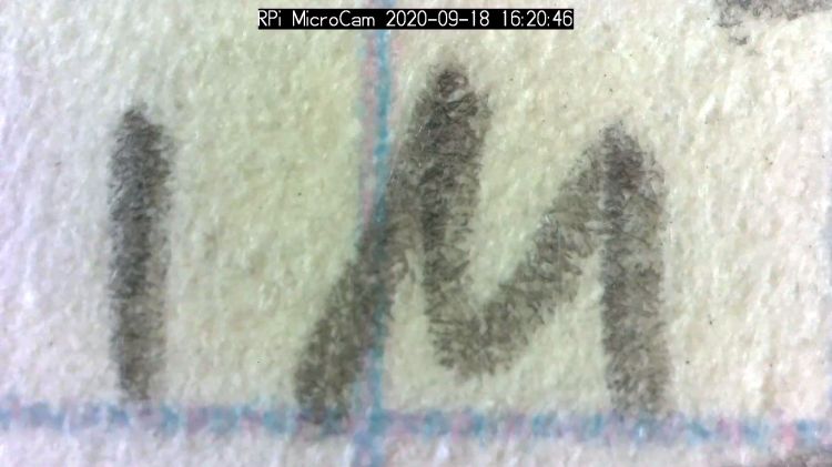
Microscope objective illuminator – RPi V1 camera image – unprocessed
What you’re seeing is the real image formed by the objective lens directly on the RPi V1 camera’s sensor: in effect, the objective replaces the itsy-bitsy camera lens. It’s a screen capture from VLC using V4L2 loopback trickery.
Those are 0.1 inch squares printed on the paper, so the view is about 150×110 mil. Positioning the camera further from the objective would reduce both the view (increase the magnification) and the amount of light, so this may be about as good as it get.
The image started out with low contrast from all the stray light, but can be coerced into usability:
The weird violet-to-greenish color shading apparently comes from the lens shading correction matrix baked into the RPi image capture pipeline and can, with some difficulty, be fixed if you have a mind to do so.
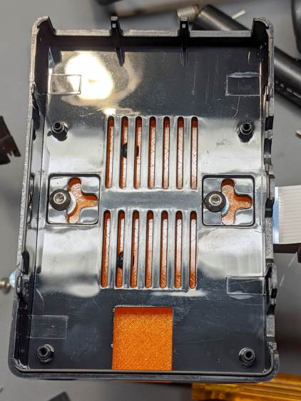
As far as I can tell, Raspberry Pi cases are a solved problem, so 3D printing an intricate widget to stick a Pi on the back of an HQ camera seems unnecessary unless you really, really like solid modeling, which, admittedly, can be a thing. All you really need is a simple adapter between the camera PCB and the case of your choice:
The plate has recesses to put the screw heads below the surface. I used nylon screws, but it doesn’t really matter.
The case has all the right openings, slots in the bottom for a pair of screws, and costs six bucks. A pair of M3 brass inserts epoxied into the plate capture the screws:
RPi HQ Camera – case adapter plate – screws
Thick washers punched from an old credit card go under the screws to compensate for the case’s silicone bump feet. I suppose Doing the Right Thing would involve 3D printed spacers matching the cross-shaped case cutouts.
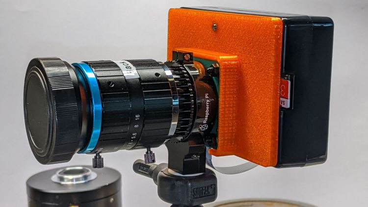
Not everyone agrees with my choice of retina-burn orange PETG:
RPi HQ Camera – 16 mm lens – case adapter plate
Yes, that’s a C-mount TV lens lurking in the background, about which more later.
This file contains hidden or bidirectional Unicode text that may be interpreted or compiled differently than what appears below. To review, open the file in an editor that reveals hidden Unicode characters.
Learn more about bidirectional Unicode characters
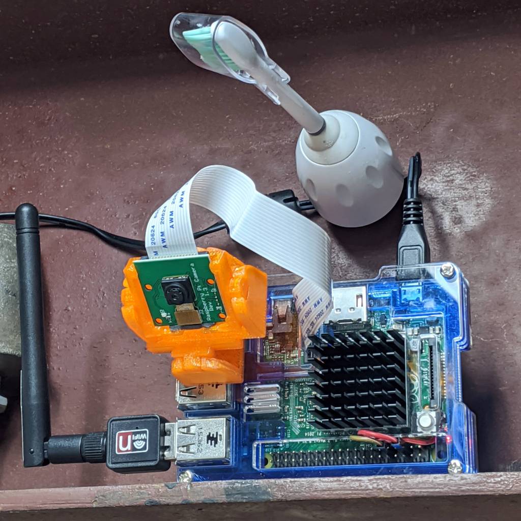
As part of spiffing my video presence for SquidWrench Zoom meetings, I put a knockoff RPi V1 camera into an Az-El mount, stuck it to a Raspberry Pi, installed the latest OS Formerly Known as Raspbian, did a little setup, and perched it on the I-beam over the workbench:
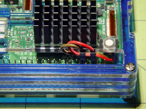
Raspberry Pi – workbench camera setup
The toothbrush head has a convenient pair of neodymium magnets affixing the RPi’s power cable to the beam, thereby preventing the whole lashup from falling off. The Pi, being an old Model B V 1.1, lacks onboard WiFi and requires a USB WiFi dongle. The white button at the lower right of the heatsink properly shuts the OS down and starts it up again.
Zoom can show video only from video devices / cameras attached to the laptop, so the trick is to make video from the RPi look like it’s coming from a local laptop device.
Start by exporting video from the Raspberry Pi:
raspivid --nopreview -t 0 -rot 180 -awb sun --sharpness -50 --flicker 60hz -w 1920 -h 1080 -ae 48 -a 1032 -a 'RPi Cam1 %Y-%m-%d %X' -b 1000000 -l -o tcp://0.0.0.0:5000
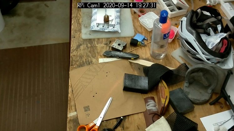
The -rot 180 -awb sun --sharpness -50 --flicker 60hz parameters make the picture look better. The bottom of the video image There is no way to predict which side of the video will be on the same side as the cable, if that’s any help figuring out which end is up, and the 6500 K LED tubes apparently fill the shop with “sun”.
The -l parameter causes raspivid to wait until it gets an incoming tcp connection on port 5000 from any other IP address, whereupon it begins capturing video and sending it out.
That’s the edge of the workbench over there on the left, looking distinctly like a cliff.
The RPi will happily stream video all day long to ffmpeg while you start / stop the display program pulling the bits from the video device. However, killing ffmpeg also kills raspivid, requiring a manual restart of both programs. This isn’t a dealbreaker for my simple needs, but it makes unattended streaming from, say, a yard camera somewhat tricky.
There appear to be an infinite number of variations on this theme, not all of which work, and some of which rest upon an unsteady ziggurat of sketchy / unmaintained software.
Addendum: If you have a couple of RPi cameras, it’s handy to run the matching ssh and ffmpeg sessions in screen / tmux / whatever terminal multiplexer you prefer. I find it easier to flip through those sessions with Ctrl-A N, rather than manage half a dozen tabs in a single terminal window. Your mileage may differ.
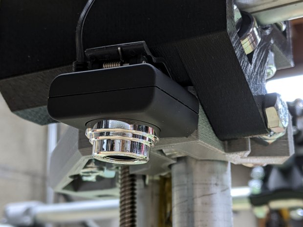
For the usual inscrutable reasons, updating bCNC killed the USB camera on the MPCNC, although it still worked fine with VLC. Rather than argue with it, I popped a more recent camera from the heap and stuck it onto the MPCNC central assembly:
bCNC – USB probe camera – attachment
This one has a nice rectangular case, although the surface might be horrible silicone that turns to snot after a few years. The fancy silver snout rotates to focus the lens from a few millimeters to infinity … and beyond!
If you think it looks a bit off-kilter, you’re absolutely right:
bCNC – USB probe camera – off-axis alignment
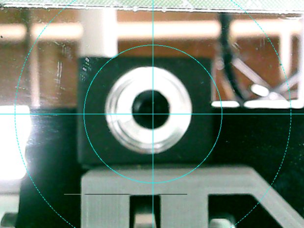
The lens image reflected in a mirror on the platform shows the optical axis has nothing whatsoever to do with the camera case or lens snout:
bCNC – USB probe camera – off-axis reflection
Remember, the mirror reflects the lens image back to itself only when the optical axis is perpendicular to the mirror. With the mirror flat on the platform, the lens must be directly above it.
Because the MPCNC camera rides at a constant height over the platform, the actual focus & scale depends on the material thickness, but this should be typical:
bCNC – USB Probe Camera – scale – screenshot
It set up a Tek Circuit Computer test deck within 0.2 mm and the other two within 0.1 mm, so it’s close enough.
The image looks a whole lot better: cheap USB cameras just keep improving …
Name: gpio-shutdown
Info: Initiates a shutdown when GPIO pin changes. The given GPIO pin
is configured as an input key that generates KEY_POWER events.
This event is handled by systemd-logind by initiating a
shutdown. Systemd versions older than 225 need an udev rule
enable listening to the input device:
ACTION!="REMOVE", SUBSYSTEM=="input", KERNEL=="event*", \
SUBSYSTEMS=="platform", DRIVERS=="gpio-keys", \
ATTRS{keys}=="116", TAG+="power-switch"
This overlay only handles shutdown. After shutdown, the system
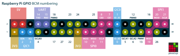
can be powered up again by driving GPIO3 low. The default
configuration uses GPIO3 with a pullup, so if you connect a
button between GPIO3 and GND (pin 5 and 6 on the 40-pin header),
you get a shutdown and power-up button.
Load: dtoverlay=gpio-shutdown,<param>=<val>
Params: gpio_pin GPIO pin to trigger on (default 3)
active_low When this is 1 (active low), a falling
edge generates a key down event and a
rising edge generates a key up event.
When this is 0 (active high), this is
reversed. The default is 1 (active low).
gpio_pull Desired pull-up/down state (off, down, up)
Default is "up".
Note that the default pin (GPIO3) has an
external pullup.
debounce Specify the debounce interval in milliseconds
(default 100)
The switch button is slightly shorter than the acrylic sheet, so it’s recessed below the surface and requires a definite push to activate. It’s not as if it’ll get nudged by accident, but ya never know.
I’ll eventually migrate this change to all the RPi boxes around the house, because it just makes more sense than any of the alternatives. Heck, it’ll free up a key on the streaming radio player keypads, although I must move the I²C display to Bus 0 to avoid contention on Pin 3.