Ed Nisley's Blog: Shop notes, electronics, firmware, machinery, 3D printing, laser cuttery, and curiosities. Contents: 100% human thinking, 0% AI slop.
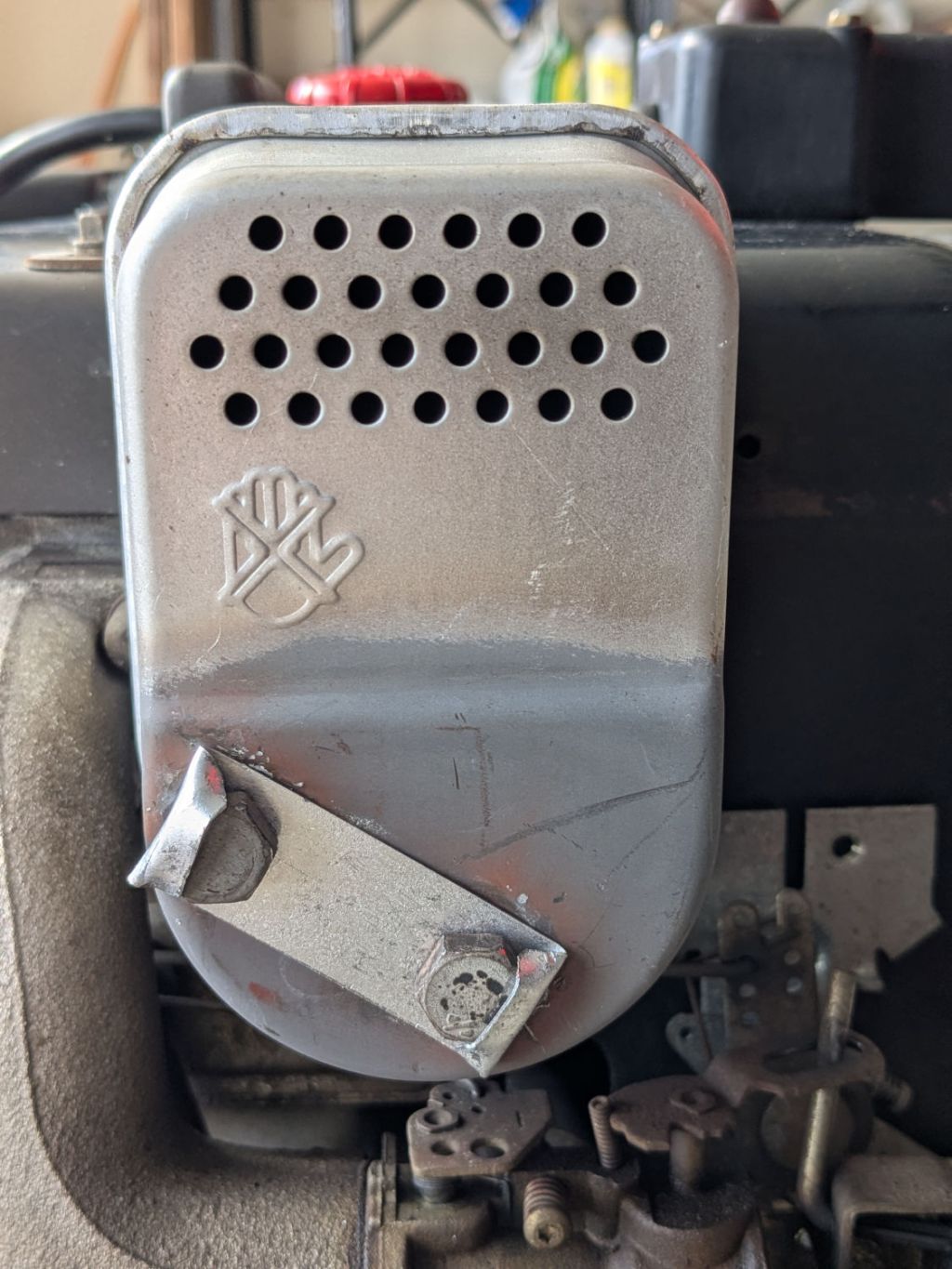
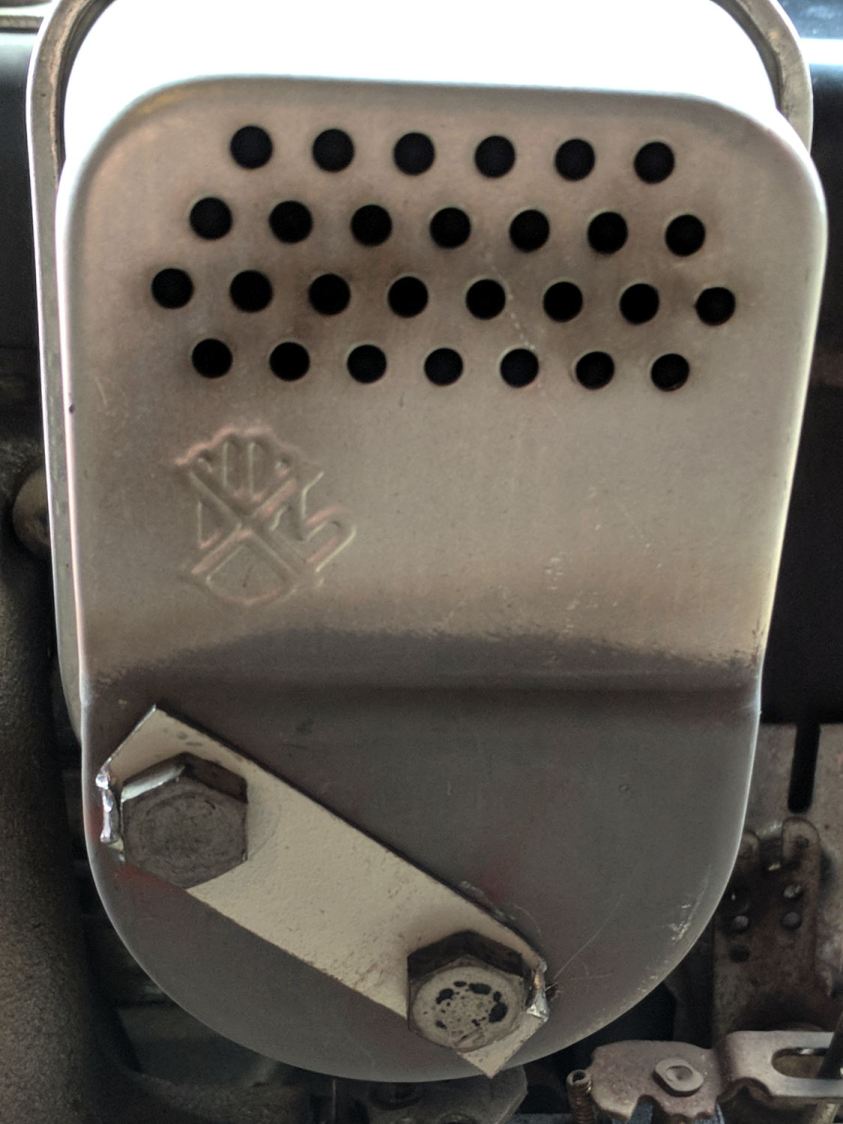
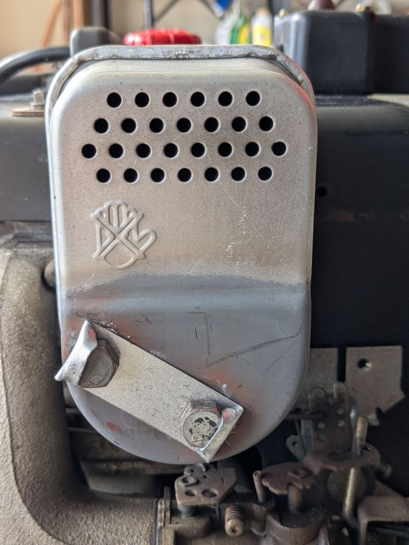
Well, it happened again, with the top bolt working its way out, so those little crimps weren’t enough. As before, I watched it happen and saw the bolt fall sizzling into the snow.
Verily it is written: When brute force isn’t working, you’re not using enough of it:
MTD Snowblower muffler
I renewed the Never-Seez on both bolts and, for good measure, dabbed some on the third bolt securing the muffler bracket atop the engine block.
Some weeks ago Mary heard a loud bang just as the lights went out. Central Hudson crews arrived shortly thereafter and began examining the transformer serving the group of houses around us. I wandered over to ask questions and learned the bang came from a high-voltage fuse atop a pole 800 feet from our house.
With all the power cables underground, the crews were locating the transformer just upstream of the problem, with the intent of disconnecting it and restoring power to everybody else. That took a few hours for our service, but folks up the hill remained in the dark maybe six more hours.
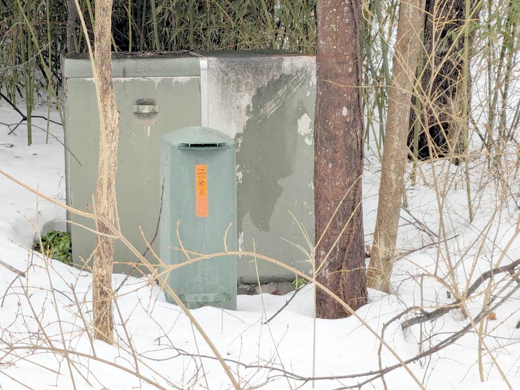
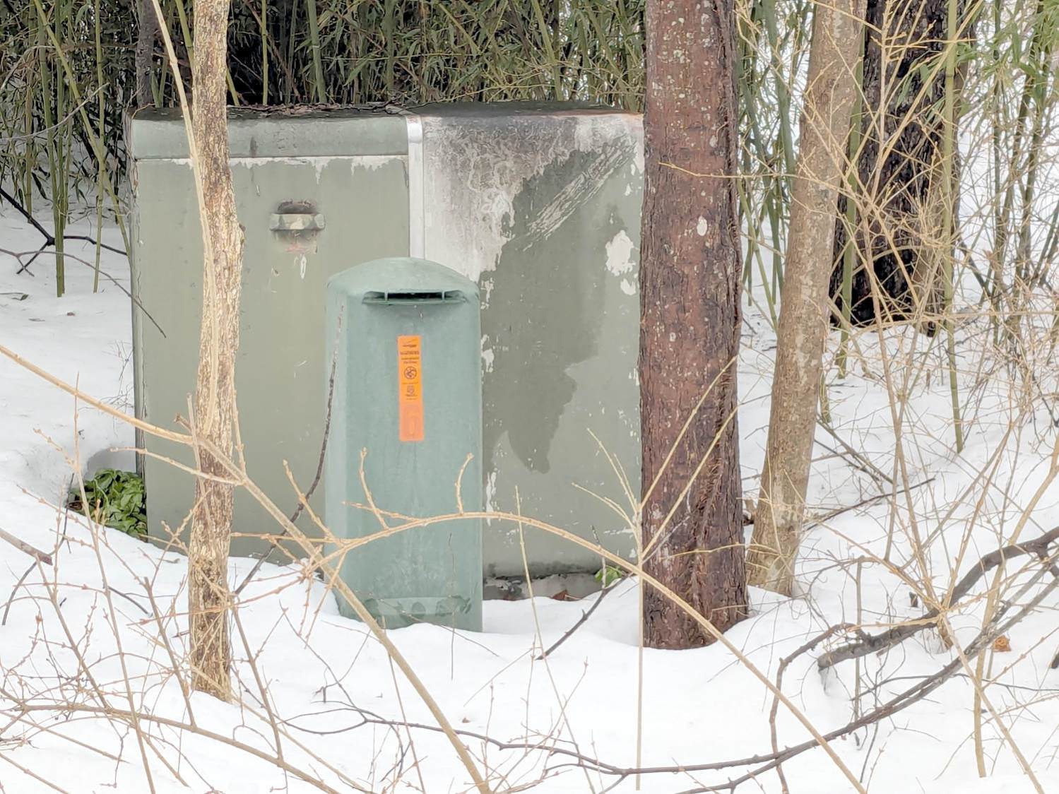
The paint on the transformer enclosures has been weathering for many decades, but I spotted this one up the hill that looks different from all the rest:
Scorched utility transformer housing
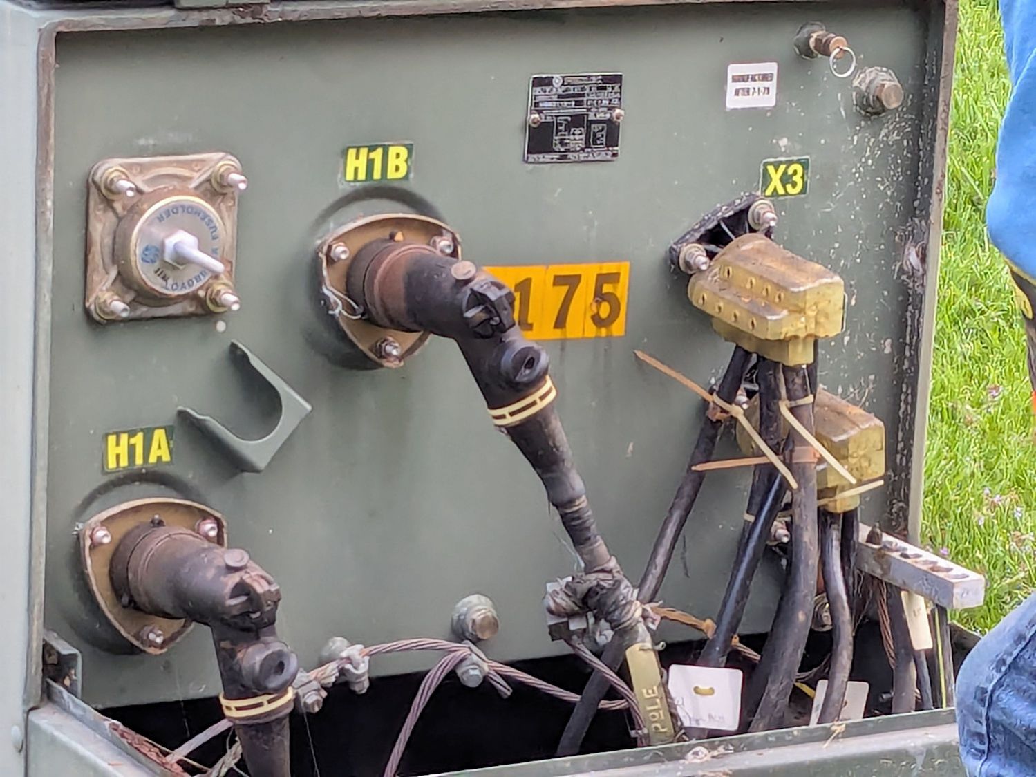
The scorched half of the enclosure pivots upward to reveal the high-voltage disconnect switch, fuses, and low-voltage connections. This one is across the street from our house:
Neighborhood distribution transformer
I think something went badly wrong in there and the transformer overheated to the point of insulation failure, whereupon the short circuit blew the HV fuse half a mile away down the hill.
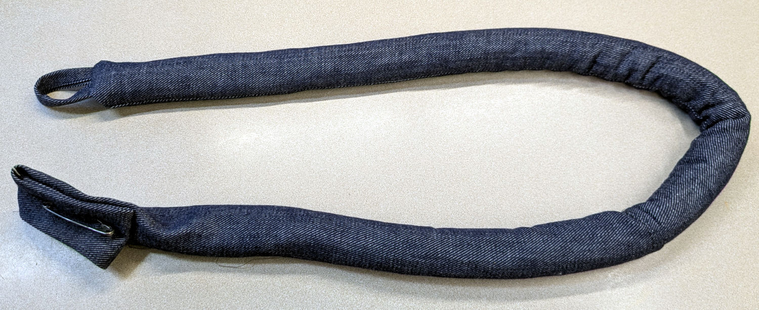
Mary made a frame weight to maintain tension on the fabric in the HQ Sixteen longarm:
Longarm fabric frame weight
It’s a sturdy cloth tube filled with BBs, somewhat like a grossly overweight door snake (a.k.a. draft stopper).
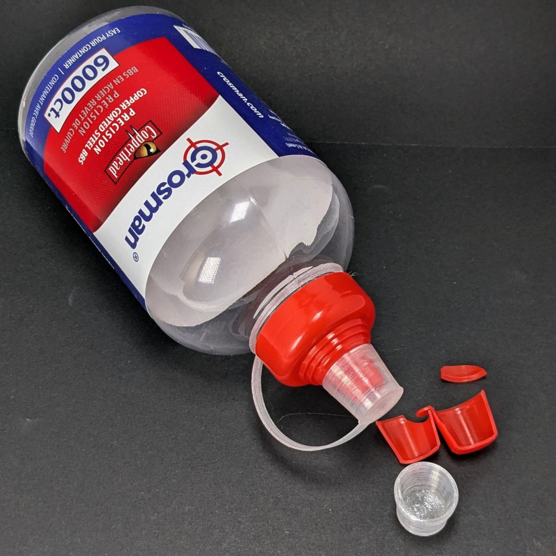
The bottle of 6000 copper-plated steel BBs arrived in an overwrap bag of the sort Amazon applies to all bottled products. This was a Good Thing, because the scrap of packing paper did nothing to cushion the bottle in an otherwise empty box. The bag contained most of the shattered cap and a few BBs, with escapees rattling around inside the box and surely a few left along the way.
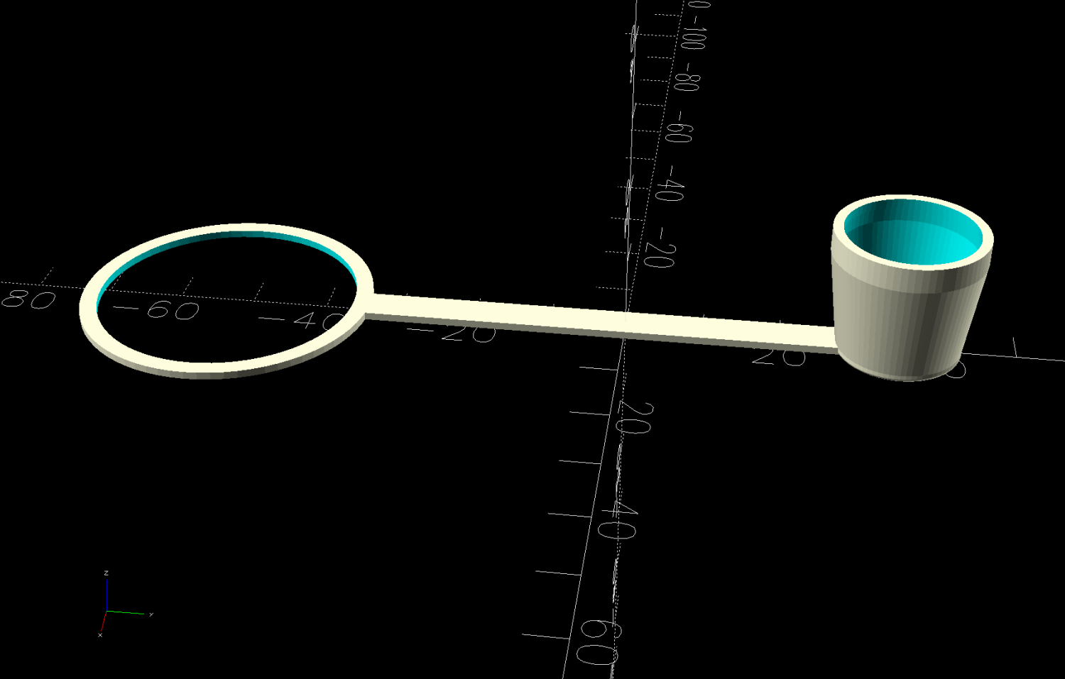
So I conjured a replacement cap from TPU:
Crosman BB bottle cap – solid model – build view
It fits around the bottle neck and snaps onto the spout just like the original:
Crosman BB bottle cap
Except this one is unbreakable.
The strapless TPU cap was a quick test to verify the fiddly shoulder snapping onto the bottle snout:
Crosman BB bottle cap – solid model – section view
As it turned out, we poured all 6000 BBs (minus those few lost-in-transit strays) into the cloth tube, but the bottle will come in handy for something someday.
This file contains hidden or bidirectional Unicode text that may be interpreted or compiled differently than what appears below. To review, open the file in an editor that reveals hidden Unicode characters.
Learn more about bidirectional Unicode characters
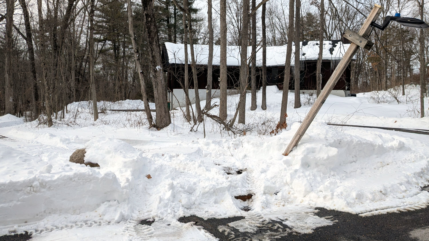
Vassar College sent a plow along the walking path linking the campus with the faculty enclave on Old Silvermine Place, but the clearance between the lamp pole and the boulder blocking the entrance wasn’t quite adequate.
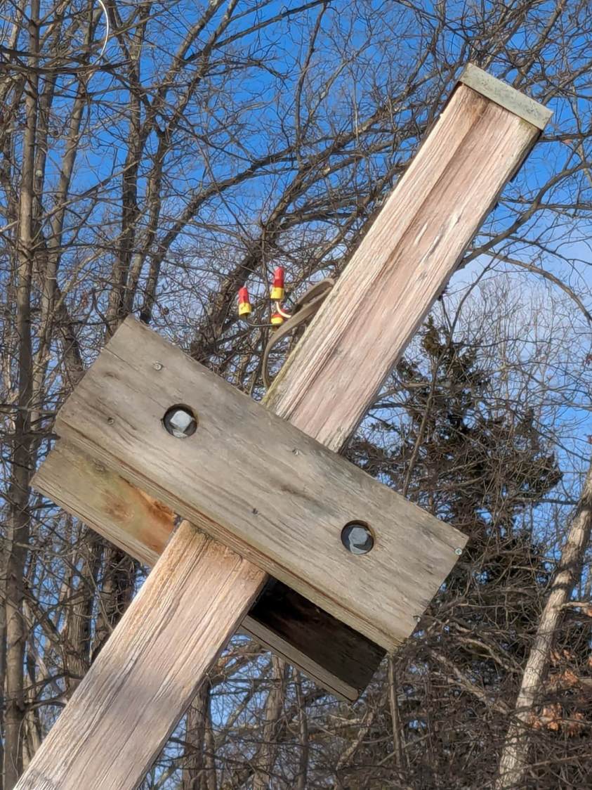
Some days later, the light fixture was missing and the power cable sported three cheerful wire nuts:
Damaged pole – wire nuts
Another pole has been lying flat on the ground for (at least) the last two years and I’ve always wondered if its wires (within easy reach) were live under their nuts. Knowing the lamp power is 277 VAC from a 480 VAC three-phase service, I’m disinclined to find out.
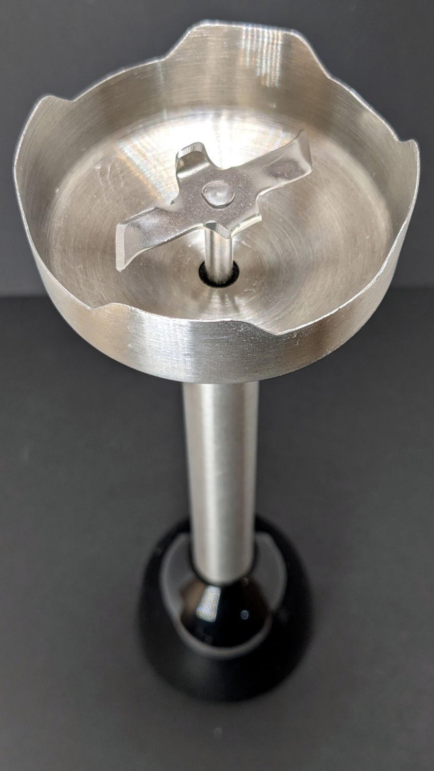
The business end of a cheap stick blender we bought a year ago to replace the previous stick blender (*):
Fresko stick blender
This one failed just slightly beyond the duration of its one-year warranty, apparently with one of the shaft bearings seized to the extent of making the blade un-turnable even by (carefully protected) finger force.
With nothing to lose (and a new blender inbound), it stood in the Basement Shop in that orientation for a week while I dripped penetrating oil around the shaft and wiggled the blade slightly back-and-forth. The bearing eventually broke free and the blade turned reluctantly.
Still having nothing to lose, I gave the shaft a few shots with a drift punch, moving it a few millimeters in each direction. This apparently disturbed the seized bearing just enough to let it turn less reluctantly, with more penetrating oil improving the situation.
Mixing a jar of water went well, even on high speed, but I doubt the bearing is in good health. We decided a blender with penetrating oil tucked up inside should be disqualified for food processing.
When it first locked up, I bought a significantly more expensive stick blender, knowing full well more money does not imply better design / better materials / more QC. This one is now designated as a Cold Backup blender for garden & shop use.
(*) For the record, my 3D printed shaft adapter failed while converting garden tomatoes into thick & zesty pizza sauce. I’m unsurprised PETG-CF wasn’t up to the task.
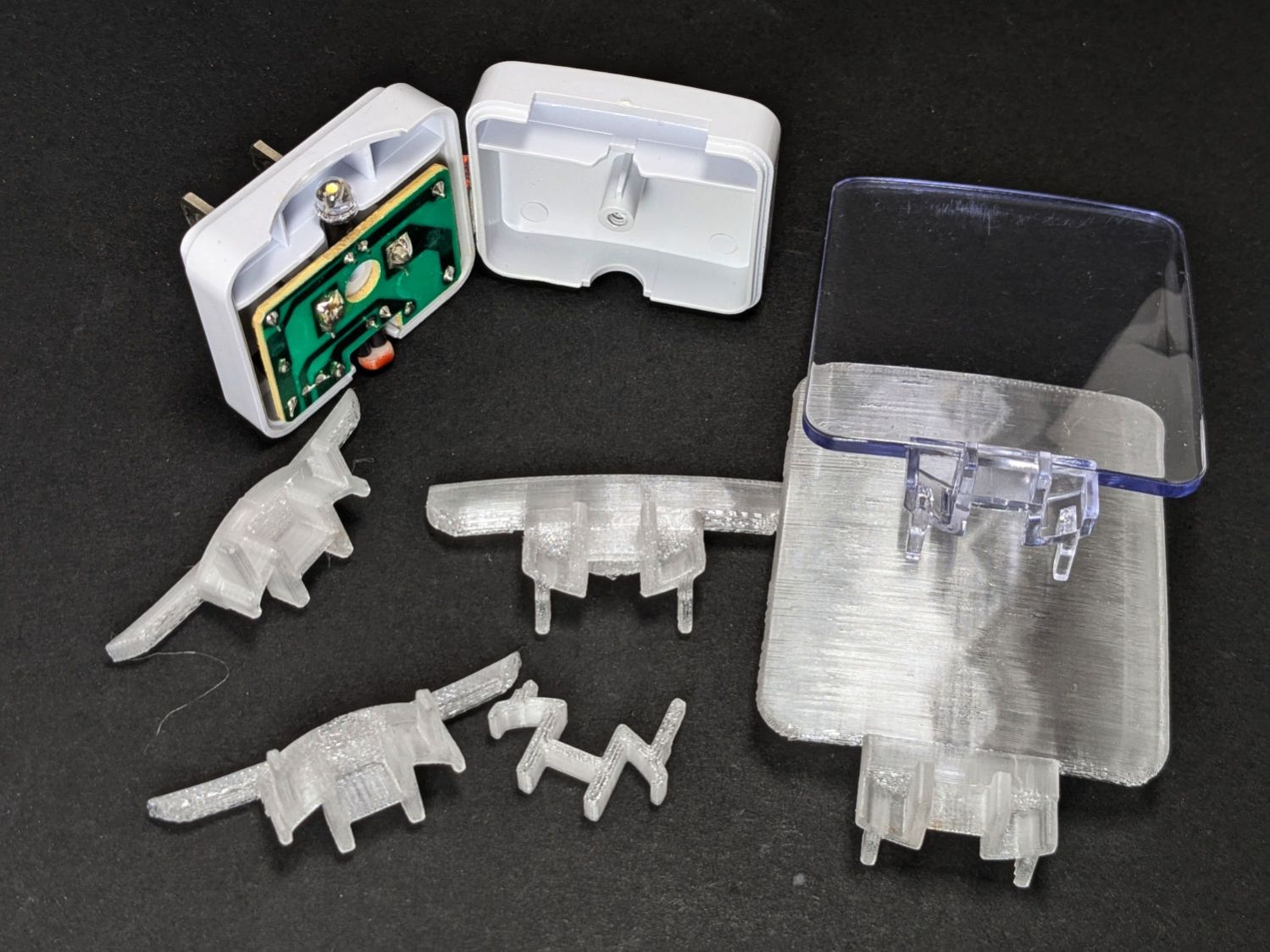
Our house came with several single-LED night lights featuring a transparent light guide / reflector:
Nightlight light guide – original
The plate had snapped off one of them and, being me, I wondered if I could replace it with something similar.
Years passed.
Obviously, this must be made from a transparent substance, which 3D printed things are not, but after some fiddling with parameters I thought the result might be informative.
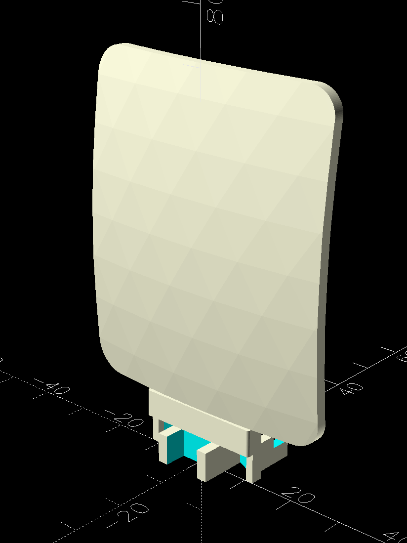
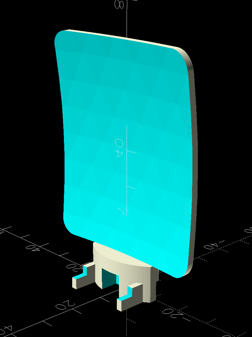
The guide plate is a section of a spherical surface, here approximated by a BOSL2 spheroid():
Nightlight light guide – view side – solid model
The original is 3 mm thick, but 2 mm worked out better for my purposes by reducing the amount of infill:
Nightlight light guide – wall side – solid model
The intricate base latches into the lamp’s plastic case:
Nightlight light guide – base – solid model
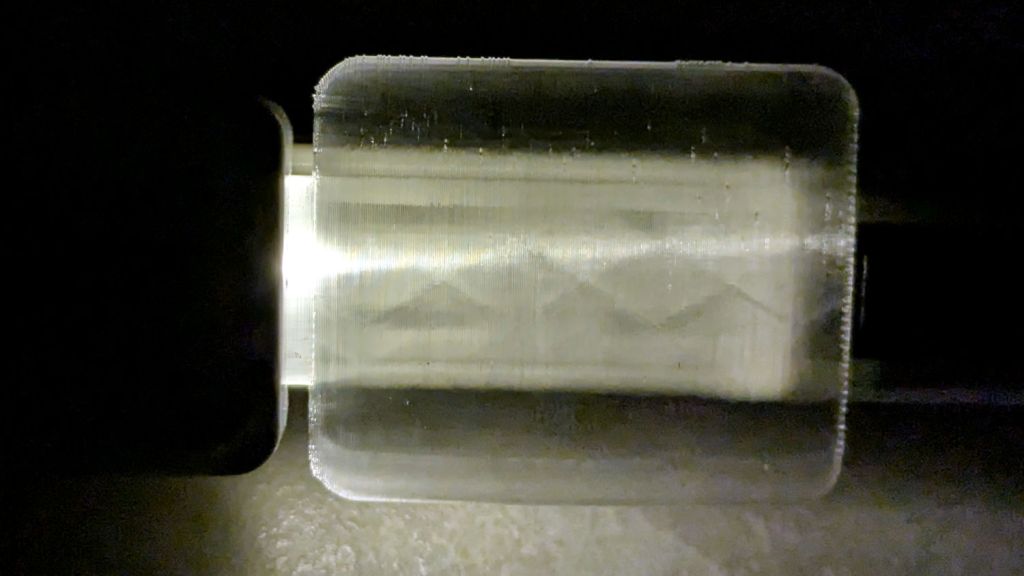
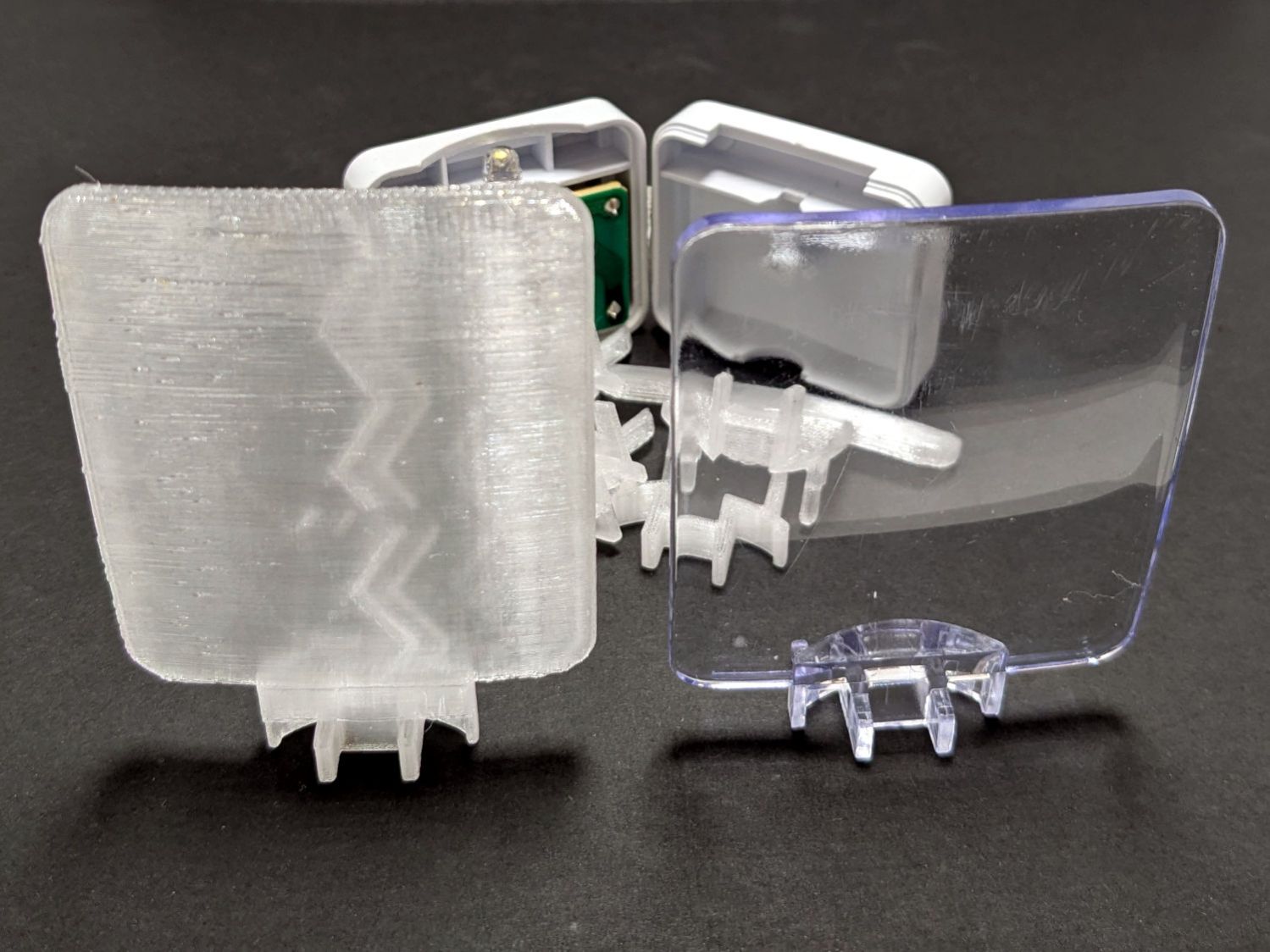
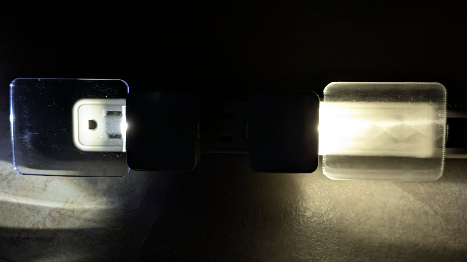
The result is, at best, translucent, because it’s definitely not transparent:
Nightlight light guide – translucent vs transparent
The zigzag pattern seems to come from the icosohedral approximation to the sphere, because it follows the surface tesselation.
Getting the base shape right required several iterations, each printed with the model cut off just above the bottom of the guide plate:
Nightlight light guide – test pieces
The first two attempts needed attention from a flush cutting pliers before fitting into the case, but they don’t call it rapid prototyping for nothin’.
The original and replacement plugged into an outlet strip:
Nightlight light guide – original vs printed on outlet strip
While you can see the vague outline of the strip behind the printed light guide, it’s definitely lacking in detail:
Nightlight light guide – outlet strip detail
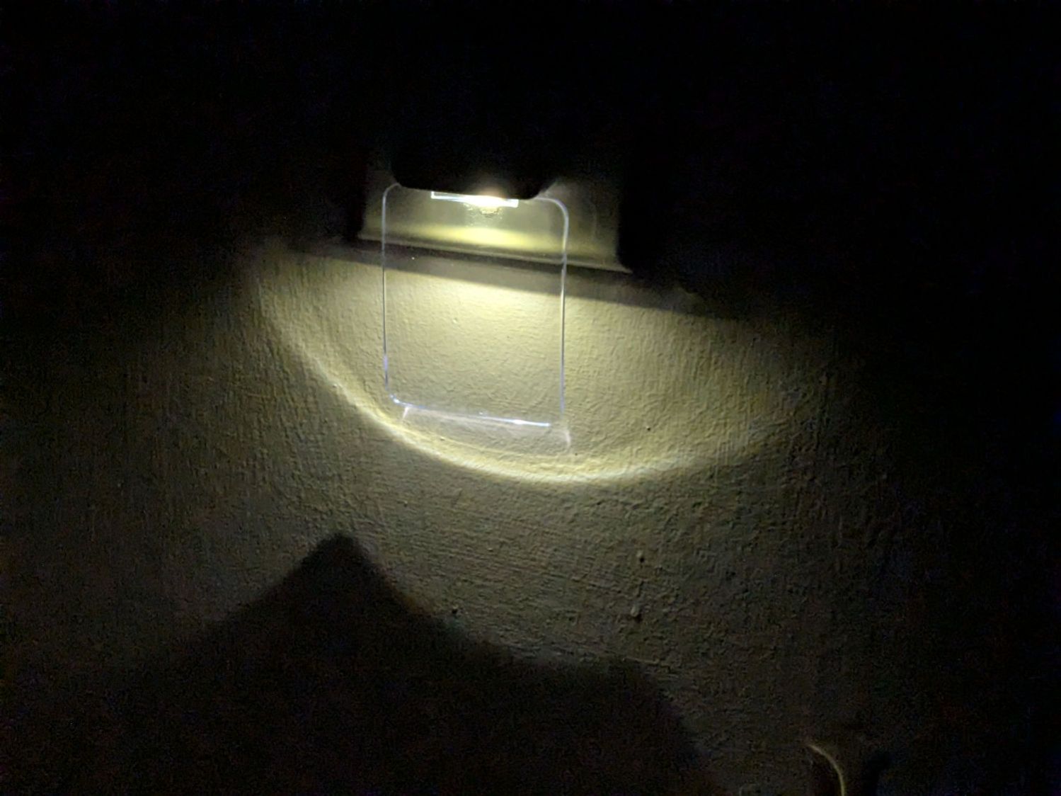
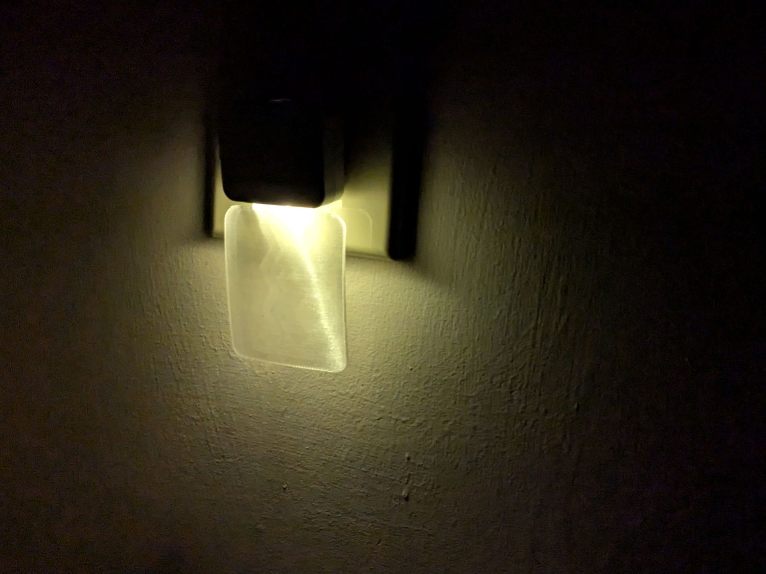
The striations throw more light into the room than the original:
Nightlight light guide – printed
Fiddling with the 3D printing parameters might make it more transparent, but it’s going back into the box it came from after giving me a better idea of which parameters to tweak the next time around.
This file contains hidden or bidirectional Unicode text that may be interpreted or compiled differently than what appears below. To review, open the file in an editor that reveals hidden Unicode characters.
Learn more about bidirectional Unicode characters