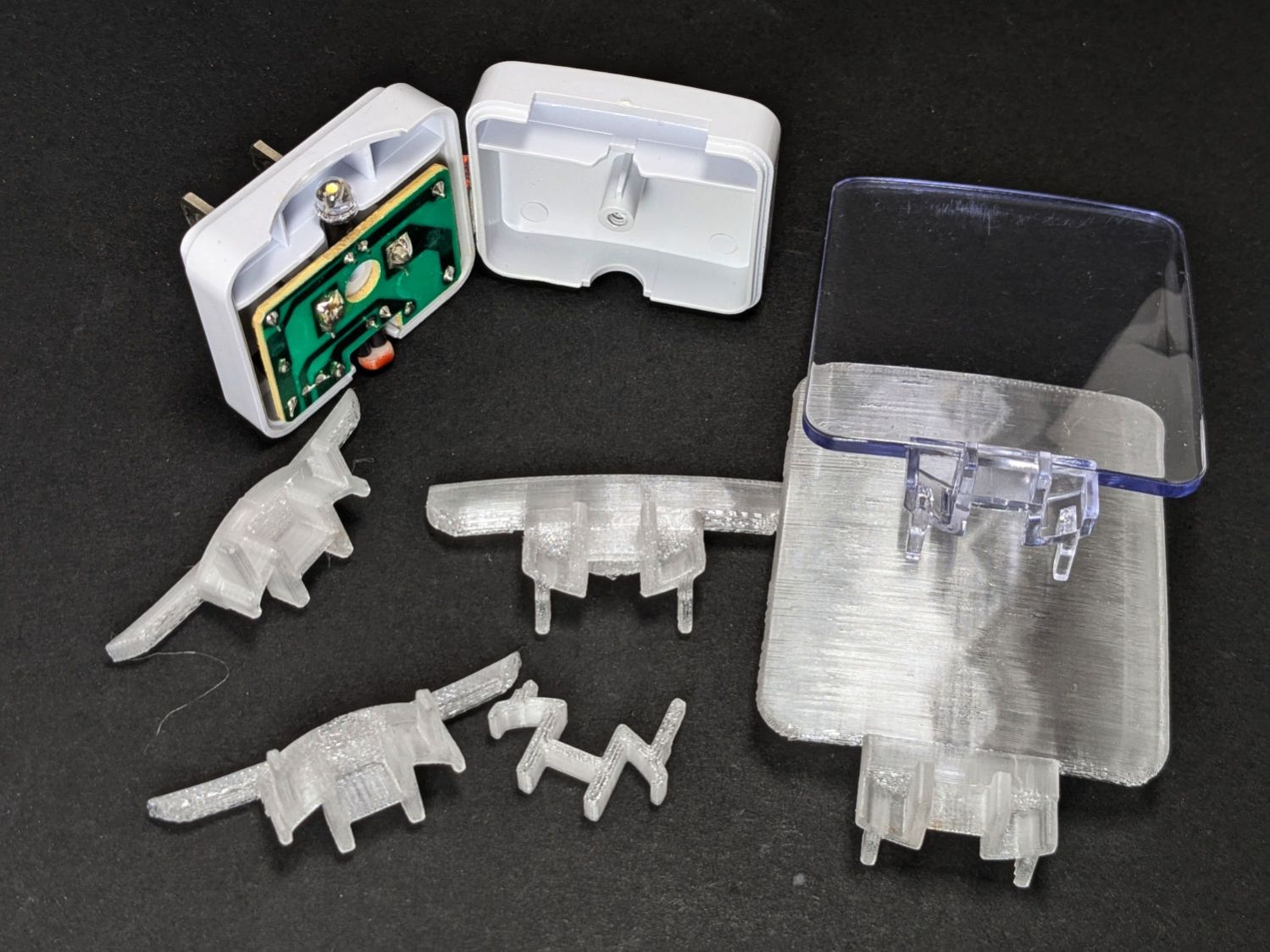
Our house came with several single-LED night lights featuring a transparent light guide / reflector:
The plate had snapped off one of them and, being me, I wondered if I could replace it with something similar.
Years passed.
Obviously, this must be made from a transparent substance, which 3D printed things are not, but after some fiddling with parameters I thought the result might be informative.
The guide plate is a section of a spherical surface, here approximated by a BOSL2 spheroid():
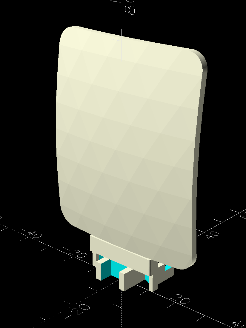
The original is 3 mm thick, but 2 mm worked out better for my purposes by reducing the amount of infill:
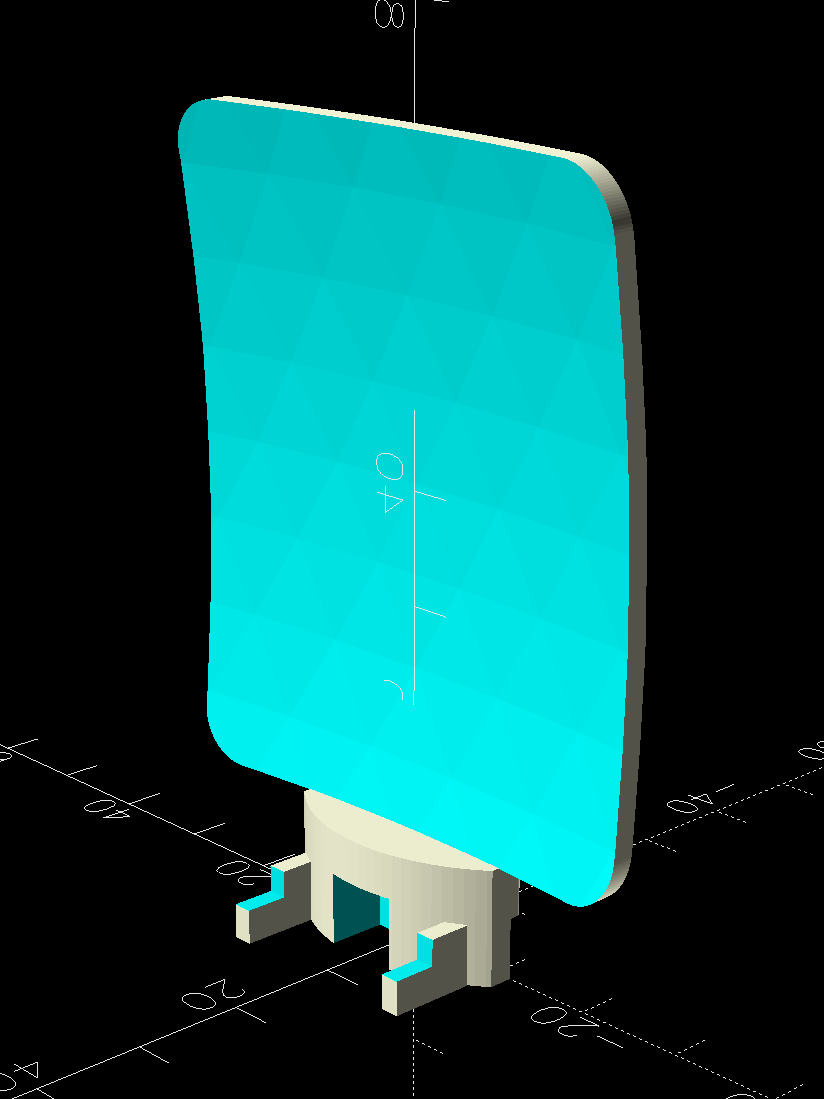
The intricate base latches into the lamp’s plastic case:

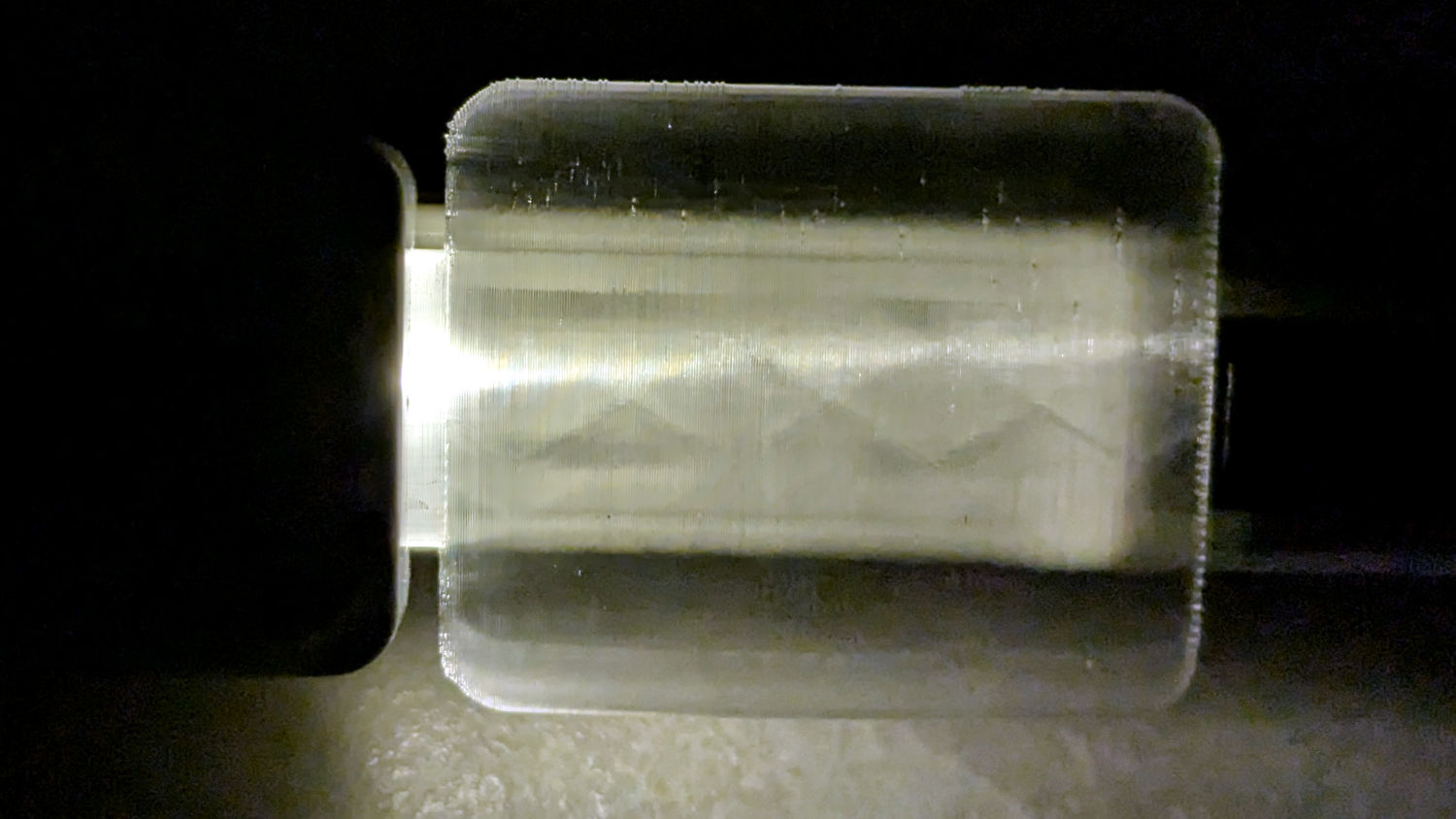
The result is, at best, translucent, because it’s definitely not transparent:
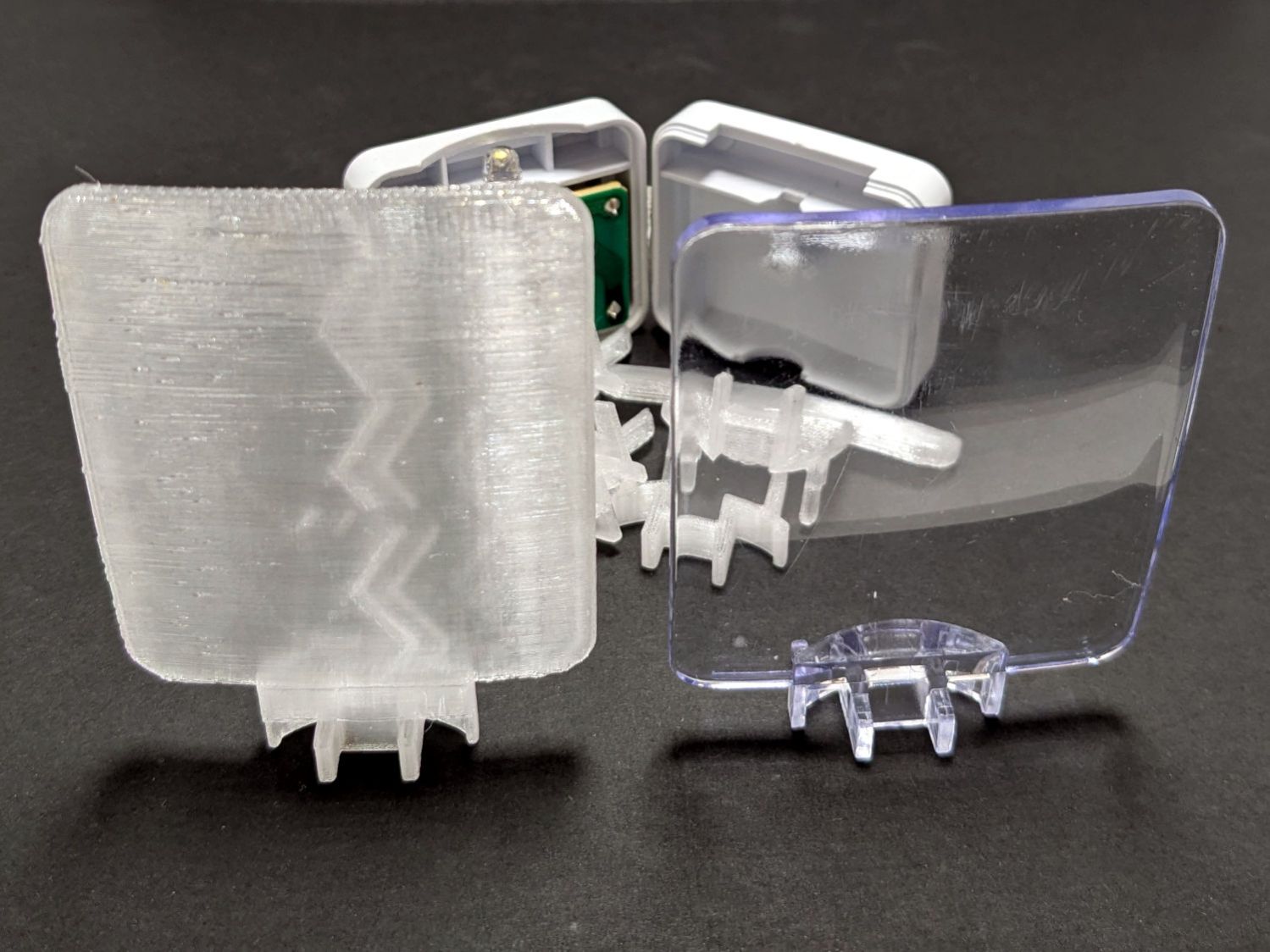
The zigzag pattern seems to come from the icosohedral approximation to the sphere, because it follows the surface tesselation.
Getting the base shape right required several iterations, each printed with the model cut off just above the bottom of the guide plate:
The first two attempts needed attention from a flush cutting pliers before fitting into the case, but they don’t call it rapid prototyping for nothin’.
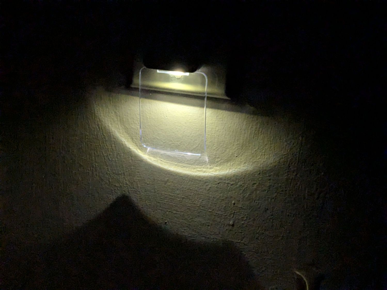
The original and replacement plugged into an outlet strip:
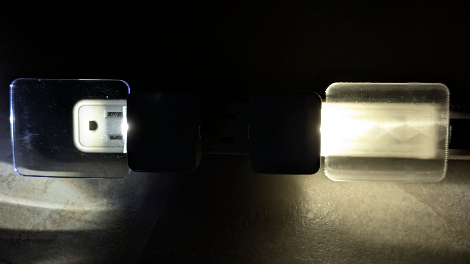
While you can see the vague outline of the strip behind the printed light guide, it’s definitely lacking in detail:
The striations throw more light into the room than the original:
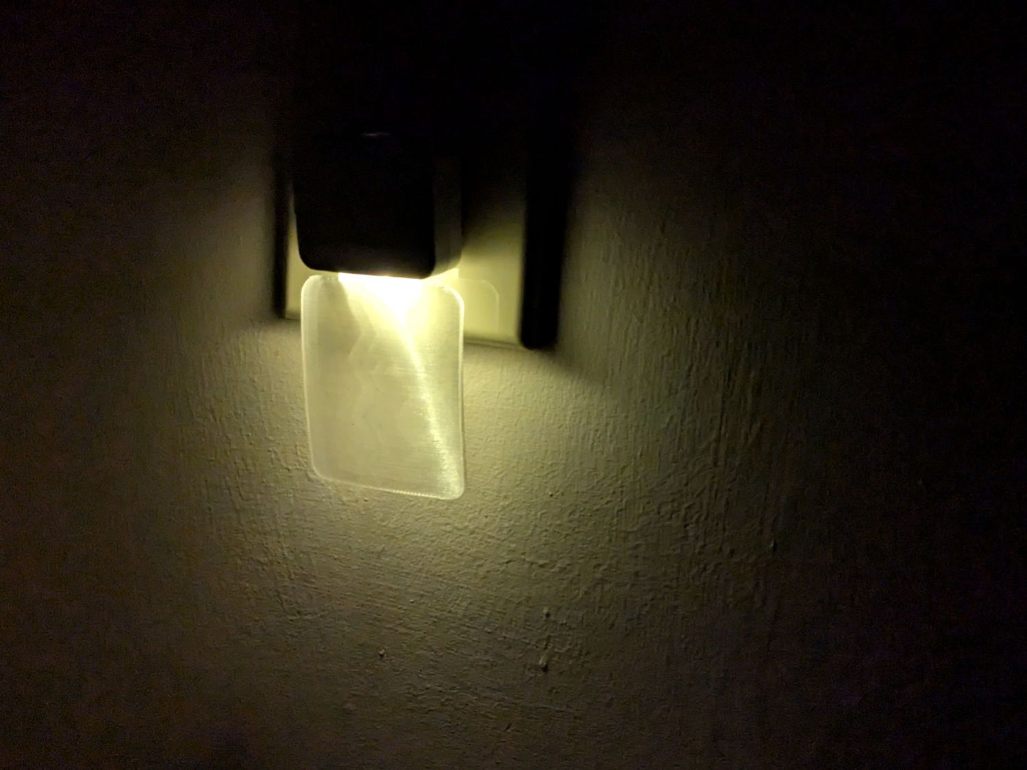
Fiddling with the 3D printing parameters might make it more transparent, but it’s going back into the box it came from after giving me a better idea of which parameters to tweak the next time around.
The OpenSCAD source code as a GitHub Gist:
| // Nightlight light guide | |
| // Ed Nisley – KE4ZNU | |
| // 2026-01-13 | |
| include <BOSL2/std.scad> | |
| Layout = "Show"; // [Show,Build,Plate,Base,Pipe] | |
| /* [Hidden] */ | |
| HoleWindage = 0.2; | |
| Protrusion = 0.1; | |
| NumSides = 10*3*4; | |
| $fn=NumSides; | |
| ID = 0; | |
| OD = 1; | |
| LENGTH = 2; | |
| function ChordRadius(m,c) = (m^2 + (c^2)/4) / (2*m); | |
| PlateThick = 2.0; | |
| PlateOA = [60.0,50.0,PlateThick]; | |
| PlateRound = 5.0; | |
| PlateTaper = 1.0; | |
| PlateAngle = atan(-2/60); // original plate angle, far end closer to wall | |
| PlateM = 2.4; | |
| PlateRadius = ChordRadius(PlateM,PlateOA.x); // light guide plate | |
| echo(PlateRadius=PlateRadius); | |
| WallThick = 2.0; | |
| MountOA = [23.4,17.0,5.5]; | |
| MountRadius = ChordRadius(4.3,MountOA.x); // base arc in housing | |
| echo(MountRadius=MountRadius); | |
| PipeThick = 5.0; | |
| //———- | |
| // Define shapes | |
| // Oddly intricate base fitting into housing | |
| // Replete with magic numbers | |
| module Base() { | |
| difference() { | |
| union() { | |
| intersection() { | |
| cuboid([MountOA.x,MountOA.y,5.5],anchor=BOTTOM); | |
| back(6.5) | |
| tube(MountOA.z,or=MountRadius,wall=1.5,anchor=BOTTOM+BACK); | |
| } | |
| for (i=[-1,1]) | |
| right(i*18.5/2) | |
| back(11.5) | |
| cuboid([1.8,8.0,MountOA.z],anchor=BOTTOM+BACK); | |
| for (i=[-1,1]) | |
| right(i*22.0/2) | |
| cuboid([1.4,2.0,MountOA.z],anchor=BOTTOM+FRONT); | |
| fwd(5.0) | |
| cuboid([11.0,10.5,MountOA.z],anchor=BOTTOM+FRONT); | |
| } | |
| down(Protrusion) | |
| for (j=[-1,1]) | |
| fwd(j*(1.5 + 10.0)/2) | |
| cuboid([7.0,10.0,MountOA.z + 2*Protrusion],anchor=BOTTOM); | |
| up(3.1) | |
| back(7.5) | |
| cuboid([MountOA.x,25.0,MountOA.z],anchor=BOTTOM+FRONT); | |
| } | |
| } | |
| // Light guide plate | |
| module Plate() { | |
| xrot(PlateAngle) | |
| zrot(90) yrot(90) | |
| left(PlateOA.x/2) | |
| down(PlateM + PlateThick/2) | |
| intersection() { | |
| up(PlateRadius) | |
| difference() { | |
| spheroid(PlateRadius,style="icosa"); | |
| spheroid(PlateRadius – PlateThick,style="icosa"); | |
| } | |
| cuboid(PlateOA + [0,0,2*PlateThick],rounding=PlateRound,edges="Z",anchor=BOTTOM); | |
| } | |
| } | |
| // Light pipe between base & plate | |
| // Magic numbers to fit case opening | |
| module Pipe() { | |
| difference() { | |
| intersection() { | |
| fwd(3.0/2 – 0.2) | |
| cuboid([MountOA.x,MountOA.y,PipeThick],rounding=0.5,edges="Z",anchor=BOTTOM+FRONT); | |
| back(6.5) | |
| cyl(MountOA.z,r=MountRadius,anchor=BOTTOM+BACK); | |
| } | |
| down(Protrusion) | |
| back((1.5 + 10.0)/2) | |
| cuboid([7.0,10.0,1.0 + Protrusion],anchor=BOTTOM); | |
| } | |
| } | |
| module Assembly() { | |
| Base(); | |
| up(MountOA.z) | |
| Pipe(); | |
| up(MountOA.z + PipeThick) | |
| Plate(); | |
| } | |
| //———- | |
| // Build things | |
| if (Layout == "Base") | |
| Base(); | |
| if (Layout == "Plate") | |
| Plate(); | |
| if (Layout == "Pipe") | |
| Pipe(); | |
| if (Layout == "Show" || Layout == "Build") | |
| Assembly(); | |

Comments
4 responses to “Translucent Night Light Light Guide”
Have you looked at the schematic of the night? A lot of them use a low voltage transistor to short out the LED, not saving any power. I suspect it is because it is cheaper than a high voltage transistor to cut power to the LED.
There’s not a whole lot of circuitry in there!
The Kill-o-Watt tells me it draws 0 W in either case, so they were pretty much lost in the roundoff.
I’d put all but one of those nightlights in the box, because streetlights brighten the house entirely enough for our needs. :grin:
How much stress is on it when installed? Is vase mode (or 0 infill) an option?
Also, for things like this I use a 0.8mm nozzle and 0.4mm layer height. Is that an option?
Zero stress: it just stands there. Until somebody bashes into it, of course, which is surely how I ended up with a broken one.
The single-layer support structures under the big paddle were very transparent, so vase mode seems like an improvement. I don’t know how well it would work as a “light guide”, but it’s gotta be prettier. :grin:
A friend has a five-head Prusa XL with a 0.8 mm nozzle and got good results from PVB + chonky layer settings. My results from the MK4’s stock 0.4 nozzle and ordinary filament are definitely on the low side of “good”. Fortunately, I’m still in test-piece territory.