The Smell of Molten Projects in the Morning

Ed Nisley's Blog: Shop notes, electronics, firmware, machinery, 3D printing, laser cuttery, and curiosities. Contents: 100% human thinking, 0% AI slop.

Tag: Repairs

If it used to work, it can work again

  • Workbench Scrap Can: Rehung

    Workbench Scrap Can: Rehung

    Somewhat as expected, the scrap can slowly and inexorably pulled the tape off the workbench.

    So I did what I should have done originally:

    Workbench scrap can - rivnuts
    Workbench scrap can – rivnuts

    Those are M5 button-head screws in rivnuts drilled into the workbench frame:

    Workbench scrap can - rivnut detail
    Workbench scrap can – rivnut detail

    With a dab of threadlock holding each screw in place, this should be forever:

    Workbench scrap can - rehung
    Workbench scrap can – rehung

    Now, I must make sawdust / swarf / chips again …

  • Chest Freezer Basket Shims

    Chest Freezer Basket Shims

    Our new chest freezer has three baskets sliding along ridges just under the lid, but they seem to be just slightly too short for the ridge spacing. After having a basket fall off the rails once too often, I cut shims from 3 mm white acrylic and stuck them in place with double-sided foam tape to soak up the extra space:

    Chest freezer basket shims
    Chest freezer basket shims

    Each shim is 300×8 mm with the neatly rounded corners that are easy to do with a laser. They may not look like they grew there, but it’s tidy enough.

    Perhaps the situation should have become a warranty claim, but a few minutes applying a tool to material I have on hand made the problem Go Away.

    Which is entirely good enough for me and pretty much what I do around here most of the time anyway.

  • Manual Drive Gear for NRC Rotary Positioner

    Manual Drive Gear for NRC Rotary Positioner

    While aligning the Sherline’s laser aligner, an old rotary positioner, apparently made by NRC, emerged from the Box o’ Optical Lab equipment:

    Rotary positioner - as found
    Rotary positioner – as found

    That’s not quite “as found”, because it came festooned with the remains of an obviously lab-built Peltier-cooled laser (?) diode fixture:

    Rotary positioner - Peltier diode fixture
    Rotary positioner – Peltier diode fixture

    The positioner sported an obviously aftermarket tapped hole in the side, presumably for mounting to a support:

    Rotary positioner - tapped mounting hole
    Rotary positioner – tapped mounting hole

    The knob was apparently intended for fine angle adjustment, but it spun freely. Loosening another setscrew on the side released its well-worn parts:

    Rotary positioner - drive gear - OEM knob
    Rotary positioner – drive gear – OEM knob

    It’s not clear what the brown ring did, back when it did something, but there were no signs of stripped-off teeth or other debris in the recess; it is a very sloppy fit on the pin holding the knob. The knob may have had a compliant surface engaging the top of the ring, made with a long-since fossilized substance.

    I figured this was a great excuse to renew my acquaintance with the BOSL2 gear generator:

    Rotary positioner - drive gear - solid model
    Rotary positioner – drive gear – solid model

    It turns out the rotary ring has triangles, not gear teeth:

    Rotary positioner - tooth detail
    Rotary positioner – tooth detail

    However, setting the gear tooth pressure angle to 45° produces a reasonable triangle:

    Rotary positioner - drive gear - solid model - end view
    Rotary positioner – drive gear – solid model – end view

    Even so, getting a functional knob required many iterations, primarily because I can’t measure any of the details and had to figure the fit by cut-and-try:

    Rotary positioner - drive gear - gallery
    Rotary positioner – drive gear – gallery

    The little white dots were an excuse to use the MMU3 for multi-material printing, because why not.

    In truth, the knob doesn’t work particularly well, as the forces from the triangular teeth on the rotary ring tend to jam the knob against its pin. The knob might work better with splines driving a squishy TPU tire riding the crests of the rotary ring teeth than a real gear. Perhaps that’s what the original brown ring did before it fossilized.

    For now, the positioner returns to the Box o’ Optics Lab Stuff, because it’s the wrong hammer for the Sherline’s laser aligner. It may emerge for a future project, when I’ll have more motivation to build a functional knob.

    The OpenSCAD source code as a GitHub Gist:

    // Rotary positioner drive gear with knob
    // Ed Nisley – KE4ZNU
    include <BOSL2/std.scad>
    include <BOSL2/gears.scad>
    NumSides = 4*3*4;
    $fn=NumSides;
    Protrusion = 0.1; // make holes end cleanly
    HoleWindage = 0.2; // make holes large enough to fit
    ShaftOD = 5.5;
    Knurling = "trunc_ribs";
    difference() {
    cyl(h=9.5,d=16.0,anchor=BOTTOM,texture=Knurling,tex_size=[3.0,4.0]) position(TOP)
    cyl(h=1.8,d=15.2,circum=false,anchor=BOTTOM) position(TOP)
    color("Green")
    scale([1.03,1.03,1]) // nominal to physical hackery
    spur_gear(diam_pitch=60.0,teeth=24,pressure_angle=45,thickness=4.7,anchor=BOTTOM);
    down(Protrusion) {
    cyl(h=1.6,d=8.2 + HoleWindage,circum=true,anchor=BOTTOM);
    cyl(h=25,d=ShaftOD + HoleWindage,circum=true,anchor=BOTTOM);
    }
    }
    color("Red")
    right((8.2 + 16.0)/4)
    cyl(h=0.6,d=2.0,circum=false,anchor=BOTTOM);

  • Gas Furnace Zone Drain Valve Refurbishment

    Gas Furnace Zone Drain Valve Refurbishment

    One of the zone valves on the gas furnace developed a slow leak around its actuator stem, so (now that the heating season is definitely over) I’ve been refurbishing all the long-neglected rubbery bits and pieces.

    The four zone drain valves showed signs of having leaked in the past, so I took them apart to replace the washers:

    Furnace zone drain valve - washers
    Furnace zone drain valve – washers

    As you’d expect, the two most-deteriorated washers were on the valves with the most corrosion.

    As I expected, the faucet washer assortment on the shelf didn’t have that size. Figuring the size based on the outside diameter produced a description of faucet washer size labels that confirmed my suspicion: it makes no sense whatsoever. In the event of link rot, a lightly reformatted version of his table:

    Faucet Washer Sizes
    Faucet Washer Sizes

    Careful measurement suggested they were 3/8L, which fit perfectly:

    Furnace zone drain valve - gaskets
    Furnace zone drain valve – gaskets

    I added the spares and a copy of that table to the washer kit, although I’m certain the next project will involve a washer with yet another nonstandard standard size.

    Replacing the washers required dismantling the valves and the first valve produced a gasket that fell out in brittle fragments. Although the remaining three gaskets emerged intact, I picked up some gasket material and laser-cut four new gaskets from the 0.8 mm sheet.

    The OD fits into the valve body rebate:

    Furnace zone drain valve - gasket installed
    Furnace zone drain valve – gasket installed

    Because these valves are closed in operation and even when open won’t operate under any significant pressure, the gaskets aren’t particularly critical, but I dabbed joint compound into the body threads just to be sure.

    And, while I was ordering things, I got a set of knobs to replace the sad bent wreckage on their stems.

  • Dripworks Mainline Leak: Repair Under Field Conditions

    Dripworks Mainline Leak: Repair Under Field Conditions

    A large gooey puddle helped isolate a leak in the Dripworks main line pipe running the length of Mary’s Vassar Farms plot:

    Dripworks Mainline clamp - injured hose joint
    Dripworks Mainline clamp – injured hose joint

    Much of the tubing between the transfer barb in the buried pipe and the cross coupling lies on the surface, where it’s subject to missteps. This being just a few feet inside the garden gate, it’s no surprise enough missteps caused the barb to no longer seal properly.

    So I pulled the barb out of the pipe and deployed the backup pipe clamp I made after fixing a previous mishap:

    Dripworks Mainline clamp - installed
    Dripworks Mainline clamp – installed

    You’re supposed to wrap silicone tape while keeping its surface clean, which is obviously impossible in a hole rapidly filling with water draining from the plumbing but the clamp presses the tape firmly against the pipe and seals the leak.

    There is, I regret to say, an 8-32 stainless steel washer lost somewhere deep in the muck.

    I punched a new barb into the pipe with slightly longer tubing to the cross fitting, in the hope it’ll be more resilient.

    Another clamp with its silicone tape snippet stands ready for duty:

    Dripworks Mainline Pipe Clamp - assembled
    Dripworks Mainline Pipe Clamp – assembled

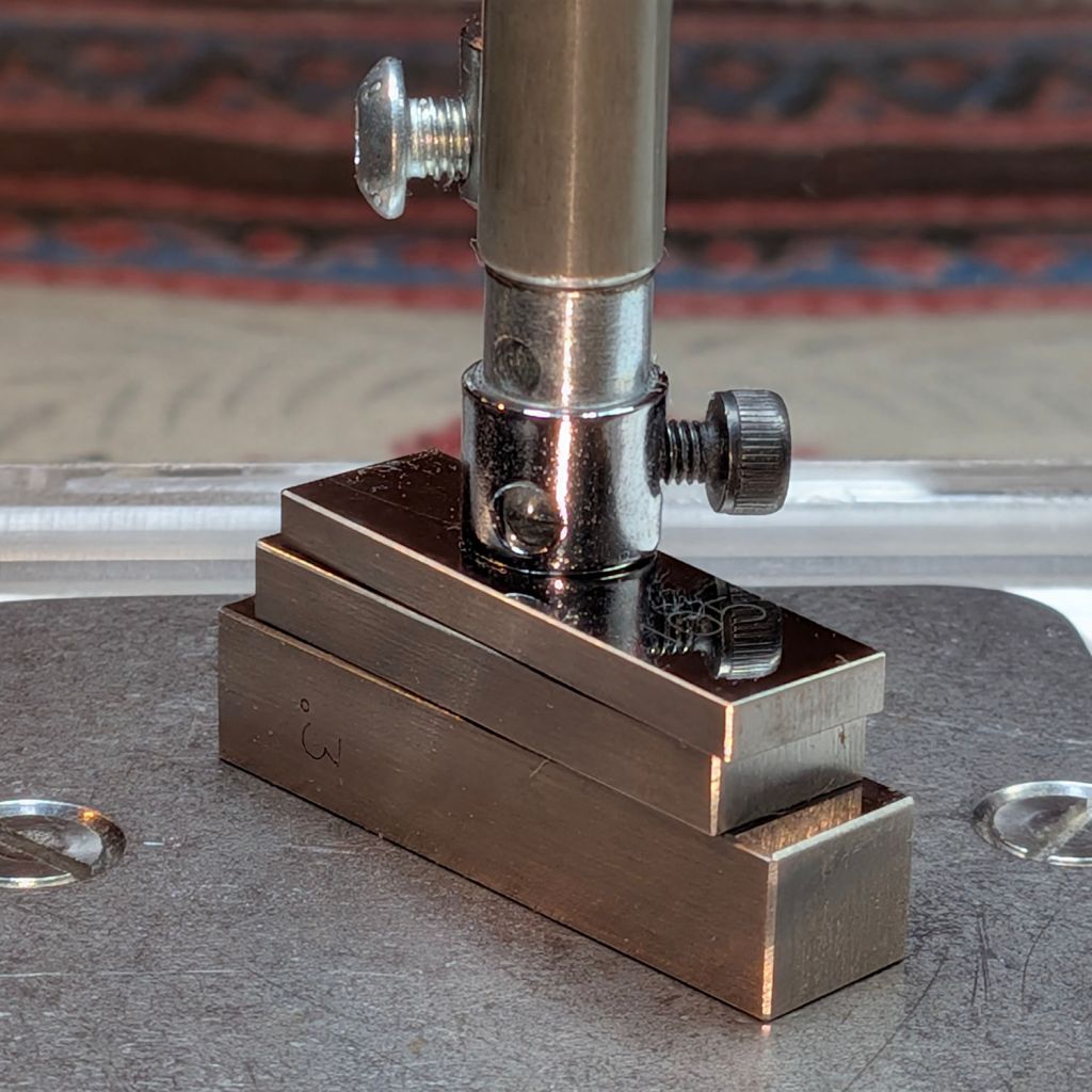
    For the record, the Micromark Cutoff Saw has a 3 mm offset between the side of the vise and the left edge of the blade:

    Micromark abrasive cutoff - work offset
    Micromark abrasive cutoff – work offset

    I still lack a Round Tuit for improving that vise.

  • BOB Yak Trailer: Fender Front Mount

    BOB Yak Trailer: Fender Front Mount

    I eventually tracked a distressingly loud rattle from the BOB Yak trailer to a fender mount failure:

    BOB Yak Trailer fender front mount - aluminum fatigue
    BOB Yak Trailer fender front mount – aluminum fatigue

    The screw clamped the round aluminum fender between two flat washers (the other of which has been touring the workbench). The hole in the aluminum started as a screw slot and eventually fretted away around the edge of the washers, leaving a trapped fragment to fall out as I loosened the screw.

    Well, this mount lasted a decade longer than the wire mount at the top of the fender, so there’s that.

    As before, a bit of math conjures a chunky mount from the vasty digital deep:

    Fender front mount - solid model - Show view
    Fender front mount – solid model – Show view

    The first iteration didn’t have the hole for the threaded insert angled downward at 10°, but it’s easier to make better measurements with a “pretty close” prototype. I’m reasonably sure the angle is a glitch due to hand-brazing the frame tubes, but we’ll never know.

    The inner plate angles to match the insert, thus keeping the screw & washer perpendicular to the surface:

    Fender front mount - solid model - Mounts view
    Fender front mount – solid model – Mounts view

    A brim around that chip of plastic ensures a good grip on the platform:

    BOB Yak Trailer - fender front mount - PrusaSlicer preview
    BOB Yak Trailer – fender front mount – PrusaSlicer preview

    I suppose rounding the corners would make it prettier:

    BOB Yak Trailer fender front mount - inner plate
    BOB Yak Trailer fender front mount – inner plate

    The original screw was slightly too short, so that’s a shiny replacement from the Drawer o’ Random M5 Screws. If I ever have occasion to go in there again, I’ll use a button head screw, although there’s certainly enough clearance:

    BOB Yak Trailer fender front mount - tire clearance
    BOB Yak Trailer fender front mount – tire clearance

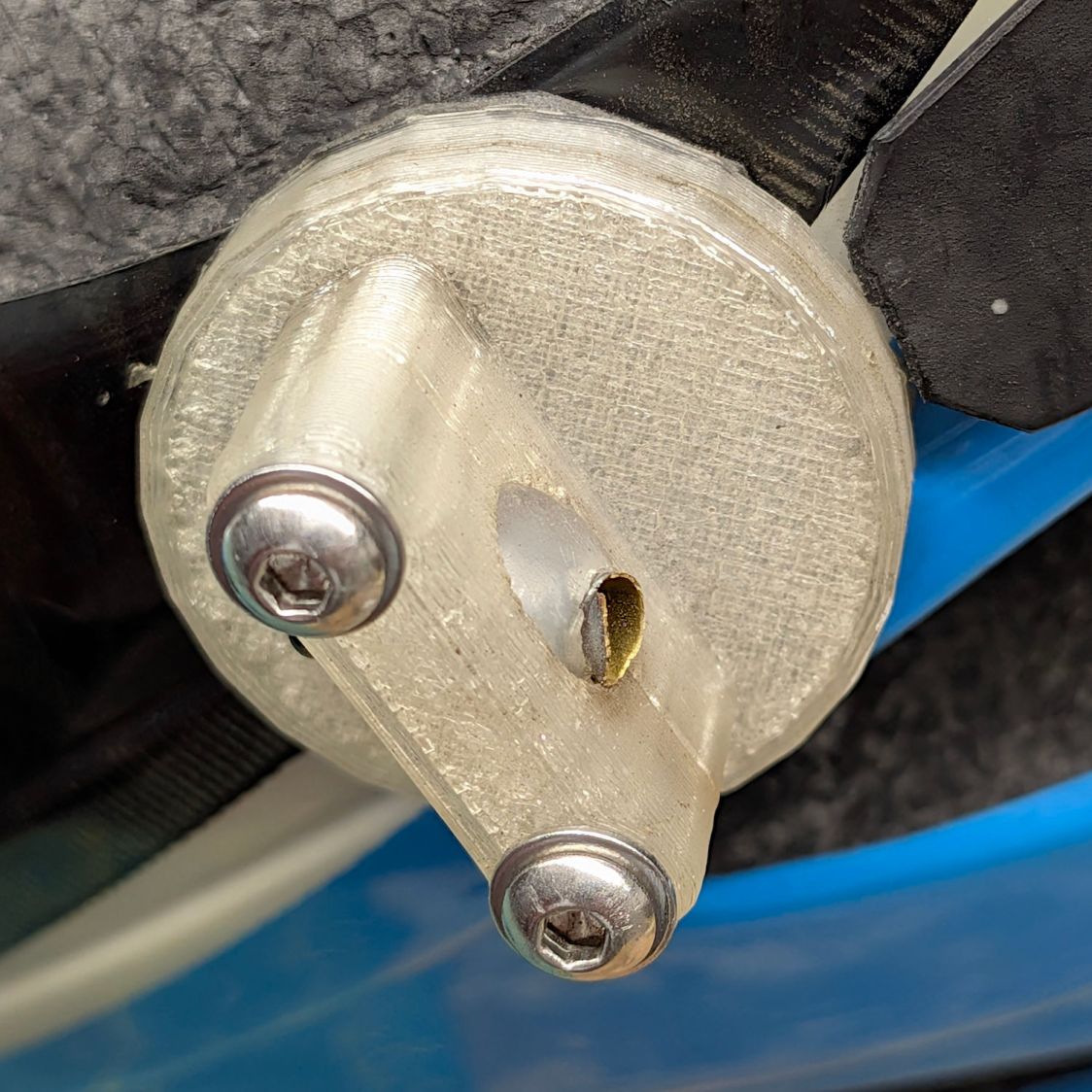
    From the top, the gray PETG-CF looks like it grew there:

    BOB Yak Trailer fender front mount - installed
    BOB Yak Trailer fender front mount – installed

    I figured the mount’s radius by feeding measurements into the chord equation and assuming the overall curve is circular; the radius came out slightly too large, which likely won’t make much difference.

    The OpenSCAD source code as a GitHub Gist:

    // BOB Yak Trailer – fender front mount
    // Ed Nisley – KE4ZNU
    // 2026-06-15
    include <BOSL2/std.scad>
    Layout = "Show"; // [Build,Show,Frame,Fender,OuterMount,InnerMount,Mounts]
    /* [Hidden] */
    ID = 0;
    OD = 1;
    LENGTH = 2;
    HoleWindage = 0.2;
    Protrusion = 0.01;
    NumSides = 4*3*2*4;
    Gap = 5.0/2;
    $fn=NumSides;
    WallThick = 5.0;
    Washer = [6.0,16.0,1.5]; // M5 fender washer
    Rivnut = [5.0,10.3,1.5]; // M5 rivnut in frame
    FrameOD = 16.1; // trailer frame tubing
    FrameAngle = 10;
    FenderOA = [52,440,1.5]; // minor major thickness
    BlockOA = [0,40.0,1.25*Washer[OD]];
    //—–
    // Define things
    // Relevant part of the trailer frame
    // origin at center of rivnut
    module Frame() {
    yrot(FrameAngle)
    union() {
    left(Rivnut[LENGTH])
    ycyl(2*BlockOA.y,d=FrameOD,anchor=RIGHT);
    xcyl(FrameOD/2,d=Rivnut[OD],anchor=RIGHT);
    left(Protrusion)
    xcyl(10,d=Rivnut[OD],anchor=LEFT);
    }
    }
    module OuterFender() {
    torus(od=FenderOA[OD],d_min=FenderOA[ID],orient=FRONT,anchor=LEFT);
    }
    module FullFender() {
    difference() {
    OuterFender();
    right(FenderOA[LENGTH]) // make it a cup
    torus(od=FenderOA[OD] – 2*FenderOA[LENGTH],d_min=FenderOA[ID] – 2*FenderOA[LENGTH],
    orient=FRONT,anchor=LEFT);
    right(FenderOA[ID]/2) // remove inner half
    ycyl(2*BlockOA.y,d=FenderOA[OD] – FenderOA[ID],anchor=LEFT);
    down(2*Washer[OD]) // remove bottom part
    cuboid(2*[FenderOA[OD],FenderOA[OD],FenderOA[OD]],anchor=TOP+LEFT);
    }
    }
    module OuterMount() {
    difference() {
    right(FenderOA[ID]/2)
    cuboid([FrameOD/3 + Washer[LENGTH] + FenderOA[ID]/2,BlockOA.y,BlockOA.z],
    rounding=1.0,anchor=RIGHT);
    Frame();
    OuterFender();
    }
    }
    module InnerMount() {
    difference() {
    render()
    intersection() {
    yrot(FrameAngle)
    cuboid([WallThick + FenderOA[LENGTH],BlockOA.y,BlockOA.z],anchor=LEFT);
    right(FenderOA[LENGTH])
    OuterFender();
    }
    yrot(FrameAngle)
    xcyl(FenderOA[ID],d=Washer[ID],anchor=LEFT);
    }
    }
    //—–
    // Build it
    if (Layout == "Frame") {
    Frame();
    }
    if (Layout == "Fender") {
    FullFender();
    }
    if (Layout == "OuterMount") {
    OuterMount();
    }
    if (Layout == "InnerMount") {
    InnerMount();
    }
    if (Layout == "Mounts") {
    OuterMount();
    InnerMount();
    }
    if (Layout == "Show") {
    OuterMount();
    InnerMount();
    color("Gray",0.6) {
    Frame();
    FullFender();
    }
    }
    if (Layout == "Build") {
    up(BlockOA.z/2) left(FenderOA[ID]/4)
    OuterMount();
    up(BlockOA.z/2)
    xrot(180)
    yrot(-FrameAngle)
    InnerMount();
    }
  • Samsung Dishwasher Drying Fan Replacement

    Samsung Dishwasher Drying Fan Replacement

    The Samsung dishwasher (model DW80K7050US/AA 03) that Came With The House fails immediately after entering the Dry part of the cycle: a relay in the control PCB under the door goes doink, all the LEDS go off then on again, the countdown timer stops changing, and that repeats as long as you like.

    After considerable listening & pondering, I decided one event early in the Dry cycle involved starting a fan to vent the steam out of the interior. The wiring diagram shows the fan has a Fault wire: perhaps the fan has failed.

    The maintenance manual shows different fans in three different places, although the control board has a connector for only one. By process of elimination, I found the fan atop the cabinet:

    Samsung dishwasher - top view
    Samsung dishwasher – top view

    The cable from the fan in the vented compartment on the left burrows under the gray duct, around its back side, and plugs into the small white connector on the right. You must ease the cable from a row of hooks guiding it around the back of the duct, which requires slightly lifting the duct.

    Unhook the two metal straps, remove four screws from the black vent, and lift it off the top to reveal the duct outlet pores:

    Samsung dishwasher - fan duct - overview
    Samsung dishwasher – fan duct – overview

    Remove four more screws, lift the fan duct assembly just a little bit, and pry open three latches around the fan compartment with a consumer electronics case-cracking tool:

    Samsung dishwasher - fan housing
    Samsung dishwasher – fan housing

    The new fan (on the right) looks very much like the OEM fan (on the left), even though it’s the $15 version rather than the $150 version you might buy from similar randomly named sellers if you were so inclined:

    Samsung dishwasher - OEM vs new fan
    Samsung dishwasher – OEM vs new fan

    Detach the old fan & its cable, drop the new fan in place, snake its cable, plug its plug, and install All The Things in reverse order.

    Unfortunately, after shoving the dishwasher back into its cubby, the new fan didn’t change the failure at all.

    I hitched the old fan up to the bench supply and it spun just like it should. Wiring the Fault wire to a 5 V supply through a resistor shows it’s the usual tachometer signal pulsing as the rotor spins.

    Which means the next step requires more pondering and PCB probing. The failure is too consistent to be a Heisenbug, but maybe something shook loose in there.