The Smell of Molten Projects in the Morning

Ed Nisley's Blog: Shop notes, electronics, firmware, machinery, 3D printing, laser cuttery, and curiosities. Contents: 100% human thinking, 0% AI slop.

Tag: Repairs

If it used to work, it can work again

  • Tektronix 2215A Oscilloscope Power Switch Rebuild

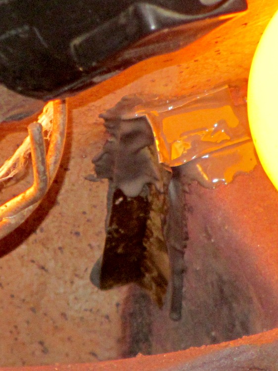
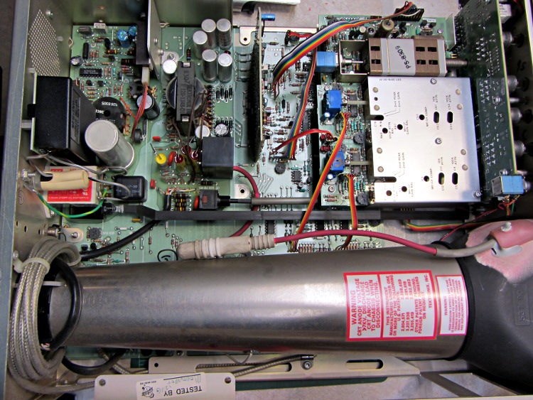
    My trusty Tek 2215A oscilloscope might be useful for a Larval Engineer engaged in late-night debugging away from the lab, but the power switch has become flaky: sometimes the ‘scope didn’t turn on at all, sometimes the switch required multiple pokes, sometimes everything worked fine. Removing the cover revealed there’s a long plastic bar connecting the power button on the front panel (to the right in the picture) to the power switch near the rear panel AC line socket, tucked under the EMI filter with the red sticker:

    Tek2215A - internal top view
    Tek2215A – internal top view

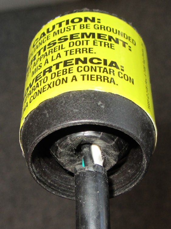
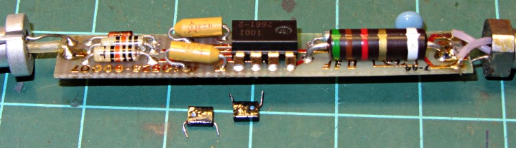
    Removing the high voltage shield below the PCB reveals the switch has DPDT terminals, but it’s wired as DPST:

    Tek2215A power switch - PCB terminals
    Tek2215A power switch – PCB terminals

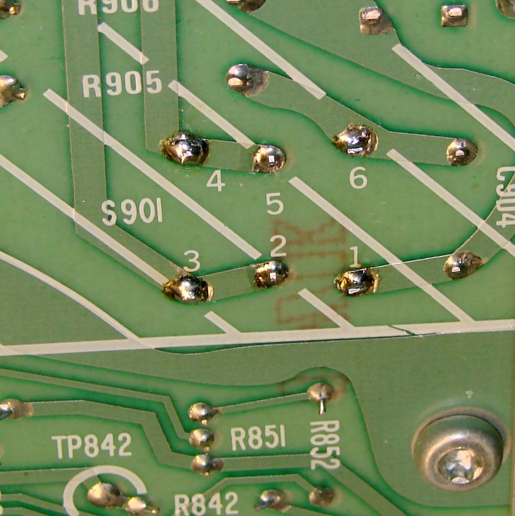
    This knowledge will come in handy later…

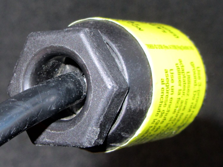
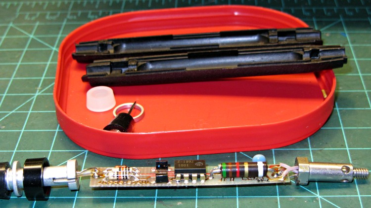
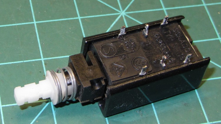
    Unsoldering the switch and wriggling the bar out of the front panel puts the switch on the bench, solder terminals upward. A plastic shell snapped around the actual switch insulates the top of the six terminals from prying fingers:

    Tek2215A power switch - bottom
    Tek2215A power switch – bottom

    Remove the shell, remove the toggle-action U-shaped steel pin, release the spring, and pull off the top plate:

    Tek2215A power switch - internal
    Tek2215A power switch – internal

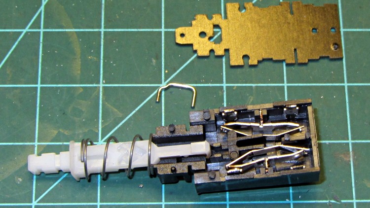
    Remove the plunger hardware, remove the rocker arms and their springs:

    Tek2215A power switch - disassembled
    Tek2215A power switch – disassembled

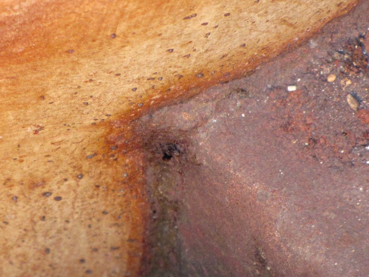
    One contact on each rocker shows signs of distress, but the other button remains pristine (having never seen any voltage differential):

    Tek2215A power switch - rockers
    Tek2215A power switch – rockers

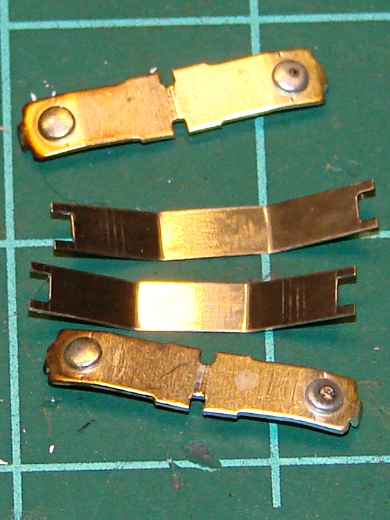
    Pull out the fixed contact tabs and note that they’ve been scorched a bit. The one on the right corresponds to the bottom rocker above:

    Tek2215A power switch - contact tabs
    Tek2215A power switch – contact tabs

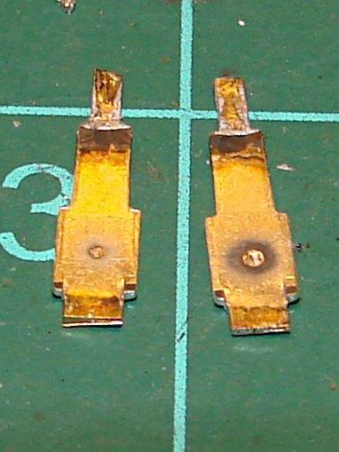
    I cleaned everything with a fiber wipe wetted in DeoxIT, then decided that I’d take the easy way out. The tabs have heavy silver plate on both sides, so I flipped them over and reinstalled them with the unused side facing the rockers. The rockers went back in with their unused contact buttons facing the flipped tabs, so we now have fresh, shiny new contact surfaces. Reassemble the switch, soldered it in place, button up the case, and a firm push on the button lights the ‘scope exactly the way it should.

    While I had the cover off, I measured the ESR of all those electrolytic capacitors: they’re in fine shape!

    The next time the switch needs repair, in another couple of decades, someone can swap in the completely unused tabs from the other end of the switch, then pick whichever contact buttons look best… [grin]

  • Wall Switch Failure

    Here’s what happens to a really old wall switch:

    Wall Switch - innards
    Wall Switch – innards

    A closeup of that broken contact:

    Wall Switch - detail
    Wall Switch – detail

    This switch controlled an outlet, so I’m sure it’s hot-switched far too many vacuum cleaners, clothes irons, and suchlike over the last half century or so.

    Our house is a bit fancier and originally had top-of-the-line mercury-wetted switches: the contacts sealed in the capsule don’t burn, but the springy supporting structures outside the capsule eventually wear out.

    They’re still more reliable than X10 switches, though.

  • Furnace Heat Exchanger: Temporary Repair

    Which small spot on this hot-air furnace heat exchanger isn’t like all the other small spots?

    Pinhole in furnace heat exchanger
    Pinhole in furnace heat exchanger

    Correct! The orange one at the corner of the rectangular exhaust gas flue that’s lit up like the sun, because you’re looking directly into the oil burner flame.

    With the fire off and everything cooled down, it looked like this:

    Pinhole in furnace heat exchanger - detail
    Pinhole in furnace heat exchanger – detail

    Now, this calls for a new furnace (because replacing the heat exchanger costs as much as a new furnace), but as it turns out this was in an unoccupied house during the week before Christmas. So I scrubbed off the debris with a steel brush, bent up a snippet of 2 mil brass shimstock to fit the corner, applied a layer of JB Industro-Weld epoxy to the problem, and positioned 200 W of incandescent bulbs to help it cure slightly sooner than forever:

    Furnace heat exchanger - temporary fix
    Furnace heat exchanger – temporary fix

    That is most certainly not a final repair, not just because the heat exchanger’s normal operating temperature exceeds the epoxy’s 500 °F rating, but because where there’s one pinhole there’s bound to be more. The goal was to let us keep the furnace running until we could schedule the replacement after the holidays. Remember, the building isn’t occupied and neither of the smoke / CO detectors went off at any point in the proceedings.

    Houses are trouble!

  • HP3970 Scanjet Lid Hinge Repair

    When the second hinge on my father-in-law’s scanner broke, he asked if I could fix it:

    HP3970 Scanjet Lid - broken hinge
    HP3970 Scanjet Lid – broken hinge

    It’s a flatbed scanner, so the lid is nearly 18 inches long and weighs 2.2 pounds with the slide / negative backlight illuminator. The stress raiser notches, located exactly where the cracks started, look like a perfect example of how not to do these things.

    I solvent-glued the hinges back together, with a square brass tube applying clamping force to the joint overnight, but this certainly won’t last for long:

    HP3970 Scanjet Lid - crude repair
    HP3970 Scanjet Lid – crude repair

    HP used to have some really smart engineers, but this looks like it was done by a Newkid (I was one, once, so I know the type) after a solid modeling and simulation session convinced him that those two thin plastic webs had enough strength for the job.

    No. They. Do. Not.

    Of course, HP provides no Official Way to repair that failure, as the hinges emerge seamlessly from the injection-molded plastic lid frame: you must scrap the scanner and buy a new one, because the lid would cost more than a new scanner. Equally of course, the fact that they don’t have a Windows driver beyond XP makes replacement a foregone conclusion.

    It runs under Xubuntu 12.04, mostly, which is what I set him up with after the XP PC got compromised.

  • Commercial Line Cord: Details Matter

    Driven by forces beyond my control, I had to rent a carpet cleaner from a local Big Box home repair store. The rugged line cord plug had an unusual (to me, anyway) strain relief fitting on the back, consisting of a circumferential clamp around the cord and a large diameter, deeply recessed opening on the nut to prevent the cord from flexing sharply:

    AC Line Cord Plug - clamp nut
    AC Line Cord Plug – clamp nut

    But something seemed odd, so I unscrewed the finger-tight clamping nut:

    AC Line Cord Plug - clamp fingers
    AC Line Cord Plug – clamp fingers

    Whoever installed the cord cut the insulation back far too much, as those fingers should close on the insulation jacket, not the conductors.

    I fought down my instinctive response, took a deep breath, clicked my heels together three times, repeated “This is not my problem”, and suddenly it wasn’t my problem any more. I tried reporting it to the harried clerk at the Big Box Store, but she instantly fluttered off to help somebody else after noting my return in the Big Book of Rental Contracts.

  • HP10525T Logic Probe: New Timing Capacitors

    HP10525T Logic Probe: New Timing Capacitors

    While putting together the PIR sensor, I had occasion to haul out the old HP10525T Logic Probe (a bookend for the Tek logic probe) to figure out why the shift register wasn’t updating; that was easier than hauling the breadboard to the oscilloscope. While it showed the problem (wire tucked into wrong hole, hidden behind a cluster of other wires), it didn’t seem to be blinking quite right. The HP10525T Logic Probe Operating and Service Manual says it should blink at about 10 Hz for any pulse train from about 10 Hz up through 50 MHz (yes, 50 megahertz), with a minimum pulse width of 10 ns (yes, 10 nanoseconds), but it didn’t do that for the PWM going to the RGB LED strip or the shift register clock.

    Given a manual printed in February 1975, I’m sure you know where this will end up…

    Update: Should you have the matching HP 10525-60015 Pulse Memory, here’s its Operating and Service manual.

    Unlike contemporary gear, the manual tells you how to dismantle the probe, using the needle tip as a tool. Doing so reveals a tidy circuit board with gold plated PCB traces:

    HP10525T - original caps
    HP10525T – original caps

    The two tiny black rectangular capacitors just to the left of the 8 pin DIP IC are C1 and C2, rated 10 μF at 2 V (yes, 2 volts). As you might expect, they had ESRs in the 3 to 5 Ω range, rather than around 0.2 Ω. The catch is that the case doesn’t have room for anything much taller, but I did contort some solid tantalum through-hole caps into the space available:

    HP10525T - replacement caps
    HP10525T – replacement caps

    Buttoned it up again and … it works fine. There really isn’t that much else to go wrong, is there?

    This picture shows the incandescent lamp glowing half-bright to indicate that the lethally sharp probe tip (on the left here, with its stud on the right in the other pictures) sees a floating input:

    HP10525T Logic Probe - glowing
    HP10525T Logic Probe – glowing

    I love happy endings, although I’m sure the accompanying HP10526T Logic Pulser needs recapping, too. When that project comes around, I’ll probably use SMD ceramic caps, because the pulser’s circuit board packs even more parts into the same volume.

    Speaking of unhappy endings, HP used to be run by real techies: The Fine Manual’s body starts with Page 0 verso, after the title and two pages of front matter. ‘Nuff said.

  • Ancient Harman-Kardon PC Speaker Re-Capping

    HK Powered Speakers - front view
    HK Powered Speakers – front view

    Suddenly a resonant thwup-thwup-thwup-thwup fills the house, but no helicopters fill the skies; in fact, most of the noise seems to be inside the house and … it’s coming from the shop. We look at each other and dash toward the basement door, knowing perfectly well that this is the part of the movie where the audience chants “Don’t open the door! Don’t open the door!

    Come to find out that it’s the pair of old Harman-Kardon powered speakers attached to the PC attached to the Thing-O-Matic; the PC is off, but I left the speakers turned on. Quick diagnostics: turning the volume down doesn’t reduce the motorboating, pulling the audio cable out of the PC doesn’t change anything, the only cure is to turn them off.

    Under normal circumstances, they’re pretty good-sounding speakers, at least to my deflicted ears, although I have my doubts about the effectiveness of that reflex port. I plugged in a pair of unpowered speakers as subwoofers down near the floor, just because they were lying around; a pair of 75 mm drivers does not a subwoofer make, fer shure.

    Pop quiz: what’s wrong?

    Need a hint? Looky here:

    HK Powered Speakers - wall wart
    HK Powered Speakers – wall wart

    Disassembly:

    • The front cloth grille has four snap mount posts, two secured by hot-melt glue blobs: pry harder than you think necessary
    • Two screws near the top of the bezel thus revealed hold it to the back
    • The bottom two screws holding the driver frame in place also hold the bezel to the back
    • Remove two screws from the grooves in the bottom of the back
    • Amazingly, the driver has two different size quick-disconnect tabs; the neatly polarized wires slide right off

    Cut the audio cable just behind the back panel, then push the two-piece cable clamp outward from the inside:

    HK Powered Speakers - cable grommet
    HK Powered Speakers – cable grommet

    The bottom of the circuit board shows considerable attention to detail. Note the excellent single-point ground at the negative terminal of the big filter capacitor:

    HK Powered Speakers - PCB foil side
    HK Powered Speakers – PCB foil side

    And, of course, that’s the problem: most of the electrolytic capacitors were dried out. My ESR tester reported the big filter cap (downstream of the bridge rectifiers) as Open and several of the smaller caps were around 10 Ω. Replacing them with similarly sized caps from the heap solved the problem.

    It should be good for another decade or two…