Ed Nisley's Blog: Shop notes, electronics, firmware, machinery, 3D printing, laser cuttery, and curiosities. Contents: 100% human thinking, 0% AI slop.
A year or so ago, I picked up a Michelin Pilot City tire (700x32C) to see how they compare with the twice-as-expensive Schwalbe Marathons we’ve been using on the Tour Easy recumbents.
Having replaced a worn-out Marathon last summer, this was unexpected:
Michelin Pilot City Protek tire – blown bead
I’d blame that failure on overpressure, but I’ve been running the back tires around 70 psi, well inside their 87 psi (that’s a nice, round 6 bar) sidewall rating.
Being able to swap a back tire in the Basement Laboratory Repair Facility made up for a lot…
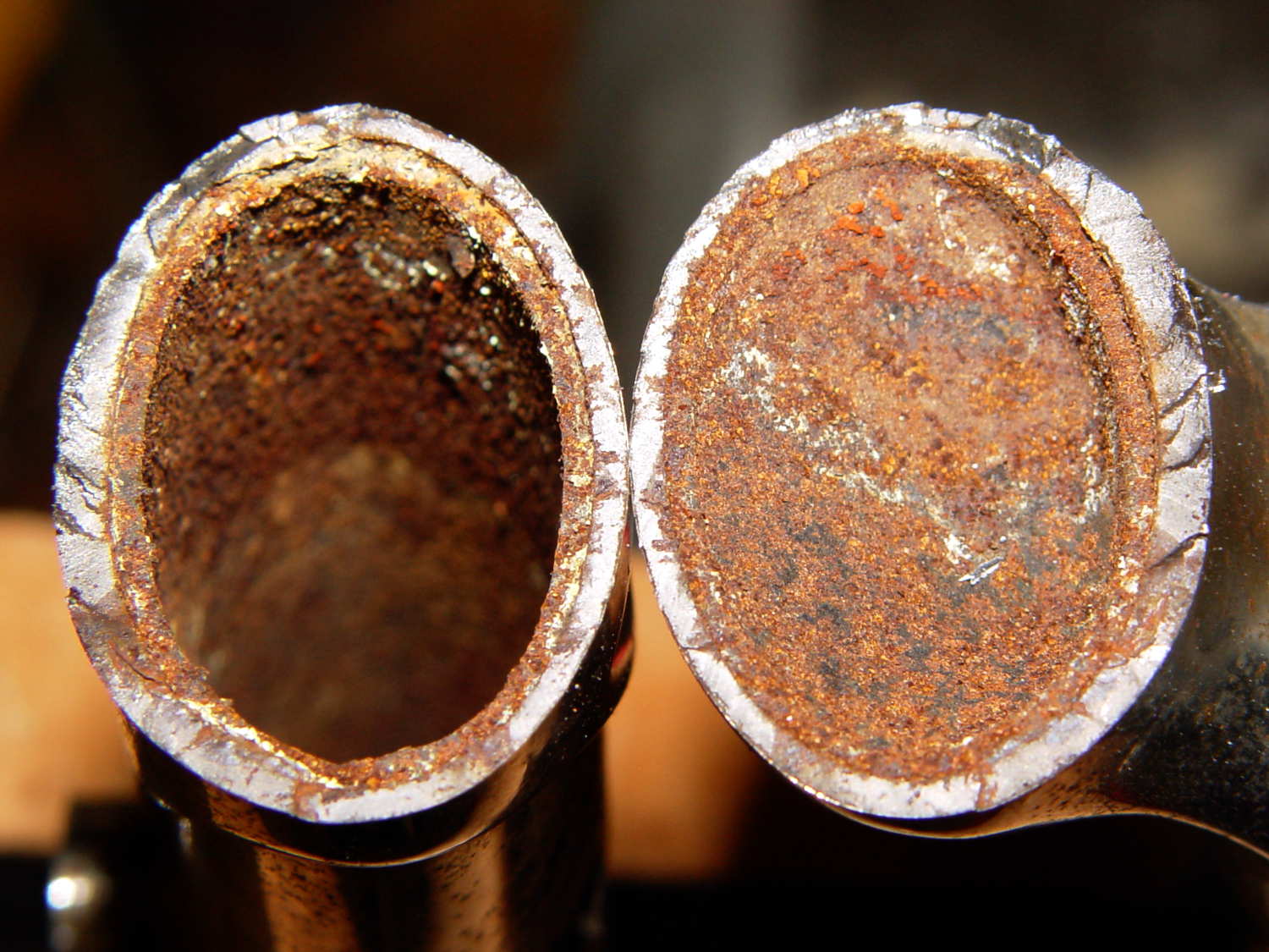
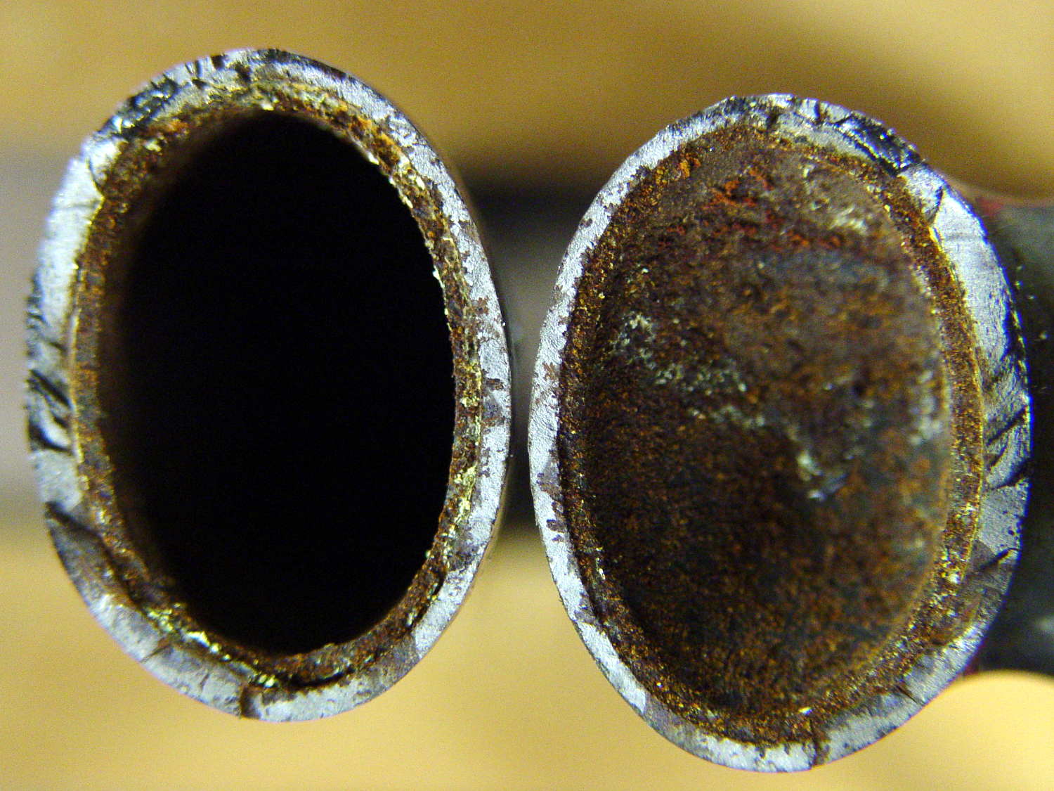
Looks rather grotendous in there, doesn’t it? Yeah, show me the interior of your fork…
The front is at the top, blade on the left and crown on the right. The little shiny rectangle at 1 o’clock on the crown was probably the last fragment holding the blade in place.
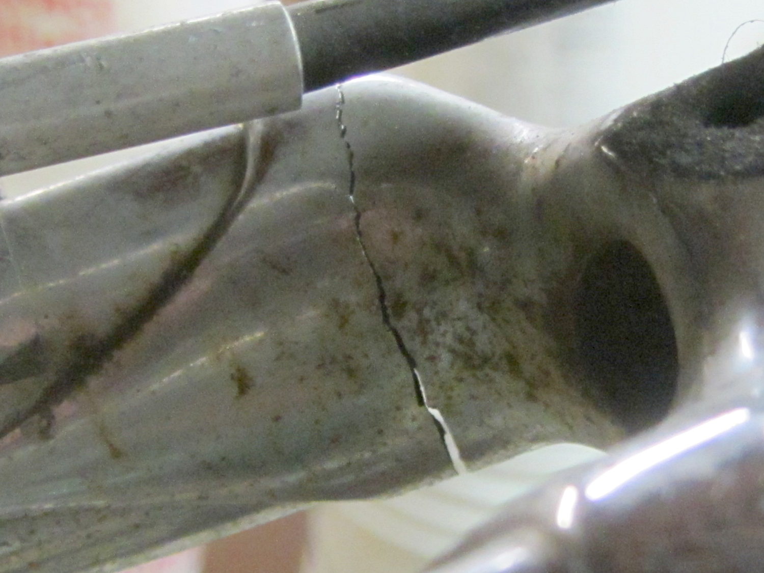
A view from the wheel side shows the crack in my Tour Easy’s fork lug had opened a bit more to the rear, which is about what you’d expect from the forces involved:
Tour Easy – cracked fork lug
Removing the handlebar stem from the fork steerer tube requires removing the fairing, its mounting brackets, the fender, a speed sensor, then snipping cable ties to release all the cables and wires. Minus the prep work, removing the fork from the bike isn’t anything special.
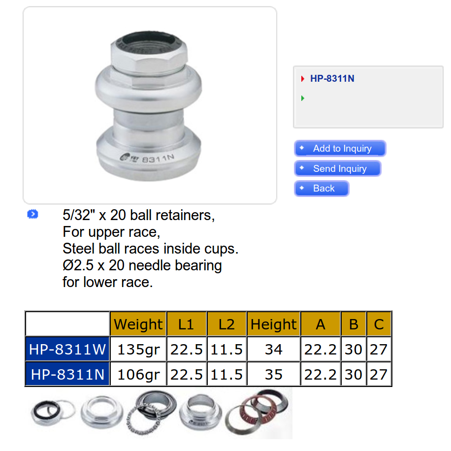
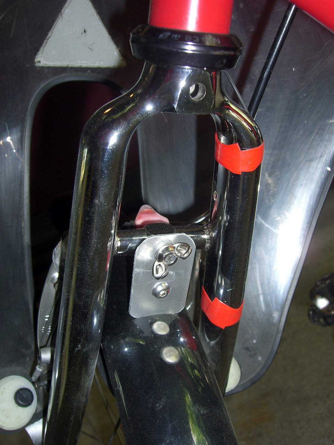
The lower bearing (a YST 8311N in black) has rollers, not balls. The headset has J.I.S. 1 inch dimensions, captured in a screen grab to forestall link rot:
YST 8311N headset data
Which means cheap & readily available ISO standard headsets aren’t a drop-in replacement. The incomparable Harris Cyclery has J.I.S. ball-bearing headsets in stock and their Tange Levin CDS HD1002 needs just 1.6 mm of additional washer to match the YST’s 35 mm stack height…
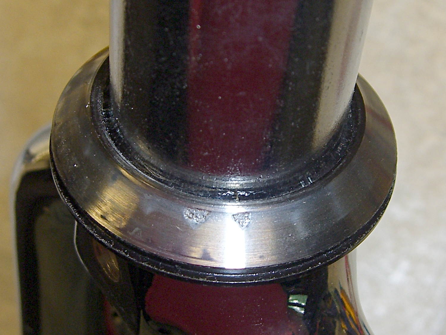
The front side of the crown got rather graunched over the last 14 years, but I punted the problem by rotating the race half a turn to put the eroded spots toward the rear, where they’ll be under minimal stress:
Tour Easy crown bearing – damage
Re-seating the race brought an ancient Headsetter tool from the drawer:
Tour Easy fork with Headsetter
It’s basically galvanized pipe, chamfered on one end, with a set of nuts & washers on a length of all-thread rod just slightly too short for the occasion: this might be the second time I’ve used the thing and I had to supply my own all-thread & nuts. Ah, well, it probably predates the Tour Easy’s design by a decade.
The lower headset race looked to be in pretty good shape, so I left it alone. Normally, such bearing damage gives you indexed steering, but Tour Easy handlebars provide so much lever arm that nothing interferes with the bike’s steering.
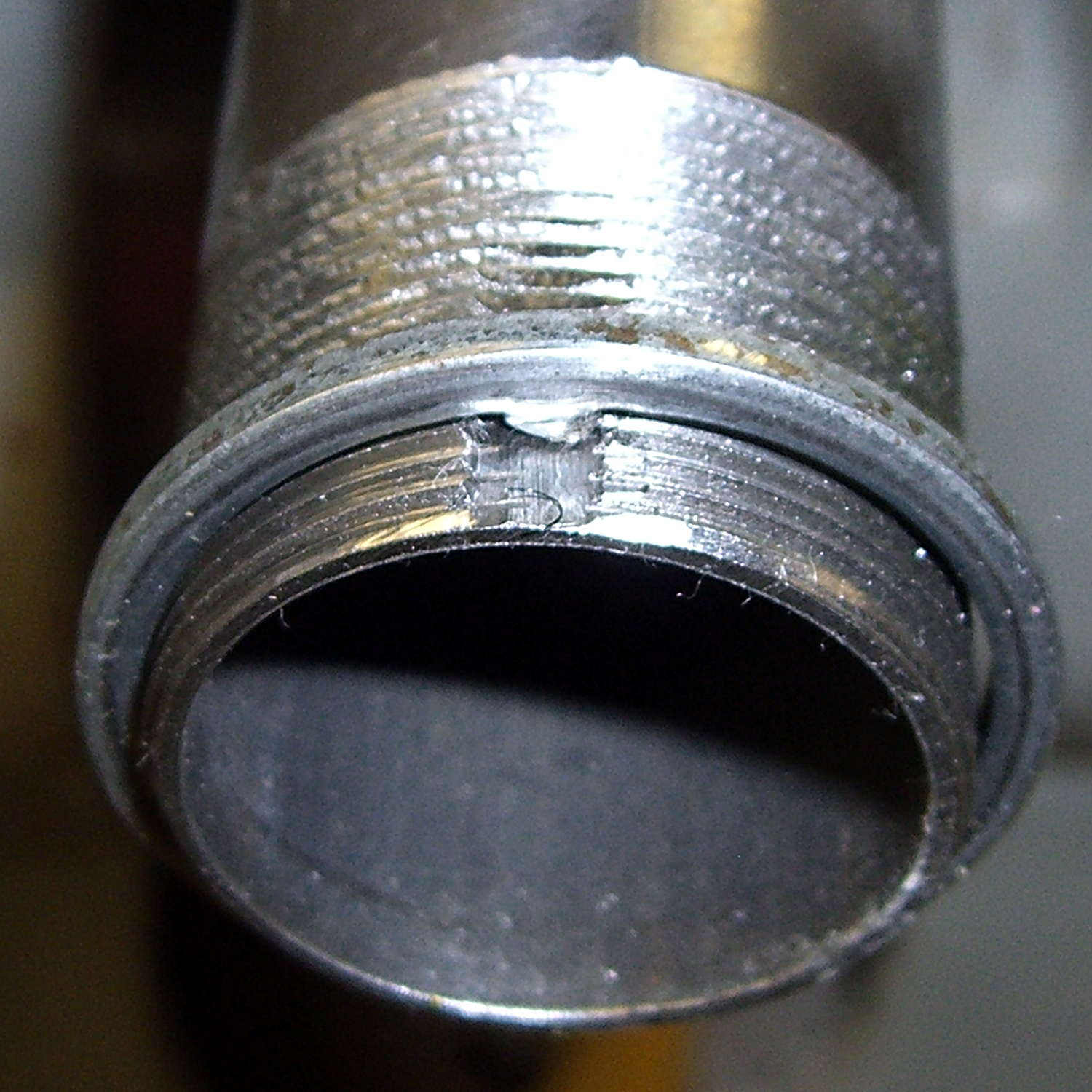
The new fork didn’t have a notch for the keyed washer isolating the locknut from the upper bearing race. The usual advice is to file off the key and apply threadlocker, which makes adjusting the two nuts tedious, so I restored the notch in the steerer threads:
Tour Easy – filed steerer tube key slot
Yes, that’s a lethally sharp steel shaving from the not-very-well-reamed ID curling up in the middle of the notch.
The fender mount bridge on the new fork sits half an inch higher in relation to the brake bosses, putting the fender against the V-brake cable hardware. Anything touching the V-brake messes up the pad-to-rim alignment, so I conjured a snippet of aluminum to lower the fender just enough to clear the brakes:
Tour Easy – new fork – fender extender
I think that calls for a nice 3D printed bracket, too, but the snippet got me back on the bike faster. When I preemptively replace the fork on Mary’s bike, then I’ll do a proper bracket for both of us.
The garish red silicone tape replaces the previous black cable ties. It matches the tube paint surprisingly well and doesn’t look good on the fork, so I’ll replace it with cable ties in due course.
A few miles of shakedown riding settled the crown race against the fork, another 1/6 turn of the upper race / lock nut snugged up the bearings, and it’s all good again.
Wow, it’s great to be back on the bike!
(Due to the vagaries of writing this stuff up ahead of time, there’s actually two weeks of realtime between the post that appeared on Monday and this one.)
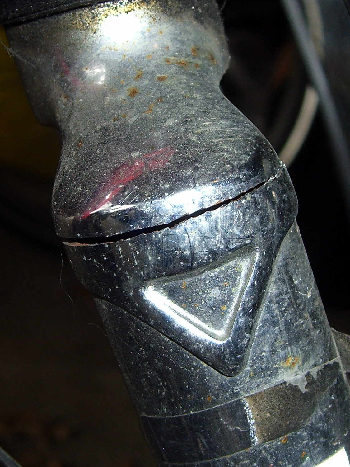
The fairing on my Tour Easy started making unusually loud booming sounds while we were out on an errand, so when we got home I poked around the front end to see what had worked itself loose. I finally managed to produce the sound, which turned out to be due to a very small motion in the fork:
Cracked Tour Easy Fork
That’s after 14 years and maybe 30,000 miles, so I’d say it did pretty well, all things considered.
On an upright bike a front fork failure kills you: the broken blade rotates forward, jams into the ground, and flips you over the handlebars. I rode about 8 miles with a broken fork and nothing exciting happened.
The Tour Easy’s design dates back to the mid-1970s, when custom bike parts weren’t readily available, and the front fork seems sized for 26 inch tires. A tubular bridge welded across just over the 20 inch (37-406) tire provides a fender mount, stiffens the blades, and, in my case, acts as a second bridge. On my bike, the fork supports the polycarbonate fairing and the Phil Wood hub provides an absolutely rigid connection between the blade dropouts.
For reference, the headset uses J.I.S 1 inch dimensions, with a 27.0 mm ID crown bearing. The stack height runs around 35 mm, but I don’t know the head tube ID.
A pair of forks are on their way; I’ll replace the one on Mary’s bike before it fails…
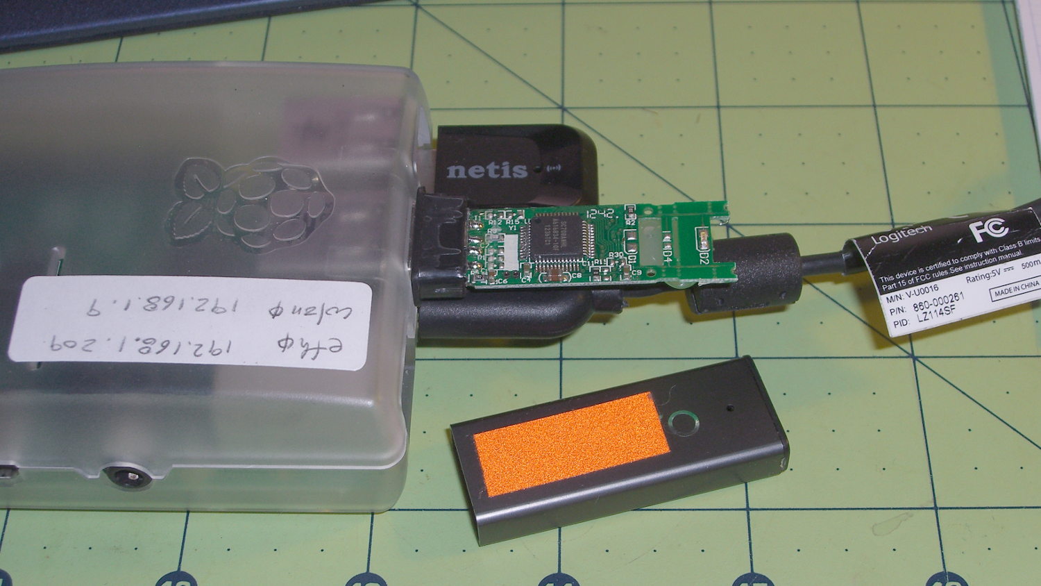
Turns out the only thing holding that case in place was a blob of hot-melt glue on the bottom of the PCB. Hot-melt glue doesn’t bond well to anodized aluminum, the RPi had been sitting outside on a winter day taking time-lapse bird feeder pictures, and the USB connector seemed a bit more snug than usual.
So I slobbered more hot-melt glue on the end of the PCB, jammed the case back in place, and that was that.
The PCB has two snap lines to accommodate shorter cases, with corresponding activity LED locations; it seems I got the long-case version.
It turns out my fancy Dell U2711 landscape monitor doesn’t work well with Displayport video. I normally leave it in power-save mode, with the power LED slowly fading orange, but about once a week it won’t start up when I turn on the PC. It seems the only solution is a hard power cycle, so I plugged it into a remotely switched outlet to eliminate having to pull its plug.
Now that I know what to watch for, it’s easy to work around: if the power LED doesn’t turn blue when the PC power goes on, immediately turn off the PC power and power-cycle the U2711. If I let the PC continue in Xubuntu, the U2713 portrait monitor becomes the primary display and X helpfully rearranges the video configuration around the disabled U2711 until I manually un-wedge things. If I shut down the PC while it’s still displaying the BIOS intro screen, then click-click the remote power switch, the U2711 will be good for another week or so.
Every month or so, the U2711 won’t light up after going into power-save mode, even though the PC is still running just fine. I set Lightlocker (which replaces the classic screensaver on Xubuntu) to blank the screen after 10 minutes and turn off the display power after 11 minutes. When the U2711 doesn’t light up, some delicate xrandr surgery through the U2713 will bring the U2711 back to life.
The starting situation looks like this:
xrandr
Screen 0: minimum 8 x 8, current 1440 x 2560, maximum 16384 x 16384
DP-0 disconnected primary (normal left inverted right x axis y axis)
DP-1 disconnected (normal left inverted right x axis y axis)
DP-2 connected (normal left inverted right x axis y axis)
   2560x1440      60.0 +
   1920x1200      59.9
   1920x1080      60.0     59.9     50.0     24.0     60.1     60.0     50.0
   1680x1050      60.0
   1600x1200      60.0
   1280x1024      75.0     60.0
   1280x800       59.8
   1280x720       60.0     59.9     50.0
   1152x864       75.0
   1024x768       75.0     60.0
   800x600        75.0     60.3
   720x576        50.0     50.1
   720x480        59.9     60.1
   640x480        75.0     59.9     59.9
DP-3 connected 1440x2560+0+0 left (normal left inverted right x axis y axis) 597mm x 336mm
   2560x1440      60.0*+
   1920x1200      59.9
   1920x1080      60.0     59.9     50.0     24.0     60.1     60.0     50.0
   1680x1050      60.0
   1600x1200      60.0
   1280x1024      75.0     60.0
   1280x800       59.8
   1280x720       60.0     59.9     50.0
   1152x864       75.0
   1024x768       75.0     60.0
   800x600        75.0     60.3
   720x576        50.0     50.1
   720x480        59.9     60.1
   640x480        75.0     59.9     59.9
Note that there’s no asterisk on DP-2’s 2650x1440 entry, which means it’s not active. In fact, it’s jammed in power-save mode and nothing other than a hard power cycle will wake it up.
The U2713 portrait monitor wakes up just fine, so X piles all the program windows into an untidy heap on that display, but, with enough Alt-Tab action, I can eventually resurface the console window and start typing:
The DP-2 and DP-3 outputs correspond to what xrandr reported above.
Then I must rearrange all the windows on both monitors again, but that’s much easier than the hocus-pocus required to recover after rebooting the PC with the U2711 shut down.
The normal (or recovered) video situation looks like this:
xrandr
Screen 0: minimum 8 x 8, current 4000 x 2560, maximum 16384 x 16384
DP-0 disconnected primary (normal left inverted right x axis y axis)
DP-1 disconnected (normal left inverted right x axis y axis)
DP-2 connected 2560x1440+0+0 (normal left inverted right x axis y axis) 597mm x 336mm
   2560x1440      60.0*+
   1920x1200      59.9
   1920x1080      60.0     59.9     50.0     24.0     60.1     60.0     50.0
   1680x1050      60.0
   1600x1200      60.0
   1280x1024      75.0     60.0
   1280x800       59.8
   1280x720       60.0     59.9     50.0
   1152x864       75.0
   1024x768       75.0     60.0
   800x600        75.0     60.3
   720x576        50.0     50.1
   720x480        59.9     60.1
   640x480        75.0     59.9     59.9
DP-3 connected 1440x2560+2560+0 left (normal left inverted right x axis y axis) 597mm x 336mm
   2560x1440      60.0*+
   1920x1200      59.9
   1920x1080      60.0     59.9     50.0     24.0     60.1     60.0     50.0
   1680x1050      60.0
   1600x1200      60.0
   1280x1024      75.0     60.0
   1280x800       59.8
   1280x720       60.0     59.9     50.0
   1152x864       75.0
   1024x768       75.0     60.0
   800x600        75.0     60.3
   720x576        50.0     50.1
   720x480        59.9     60.1
   640x480        75.0     59.9     59.9
Note that DP-2 now sports an asterisk.
The width of Screen 0 covers the U2711 in landscape and the U2713 in portrait: 4000 = 2560+1440. The height comes from the U2713 in portrait mode: 2560.
That this should not be necessary goes without saying. The U2711 run with firmware revision A09, which was supposed to fix the problem, but Dell basically walked away from it.
I’m pretty much forced to use Displayport video for both monitors, as a low-profile nVidia card with twodual-link DVI-D outputs doesn’t seem to exist. The Dell Optiplex 980 disables the system board video when it finds a PCI-E video card, so there’s no way to run the U2713 from the system board Displayport and the U2711 from a dual-link DVI PCI-E video card.
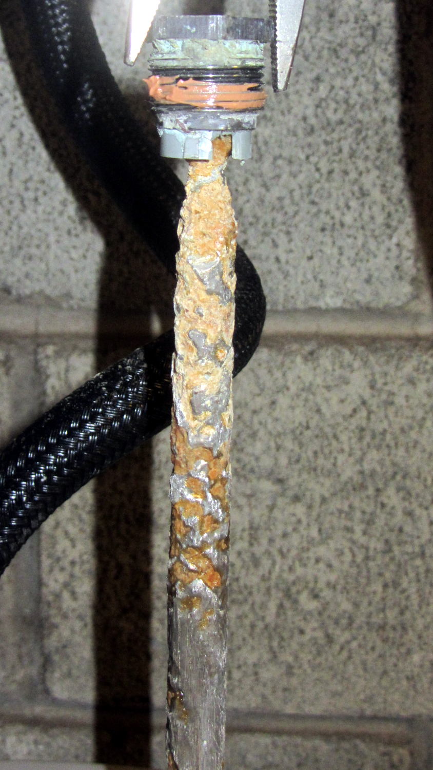
But, as before, most of the corrosion is close to the top end. The rest of the rod was covered with a thick mineral scale that I hammered off, then scuffed the rod with a shoe rasp to expose some metal.