The rods (a.k.a. tubes or poles) holding & guiding the quilt top / batting / backing fabric on Mary’s HQ Sixteen longarm quilting machine span the eleven feet of the table:
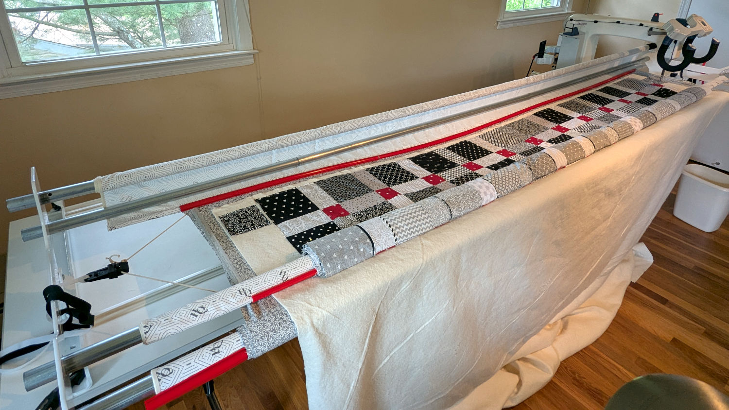
The two end plates are 1/4 inch steel plate with four punched holes for the rods / tubes, which look remarkably like EMT. The machine is two decades old and Mary is (at least) the third owner, so it’s no surprise the rods long ago wore through the white powder-coat paint on the plates and, during the course of a long quilting project, now deposit black dust on the table.
Black dust not being tolerable near a quilt-in-progress, Mary asked for an improvement.
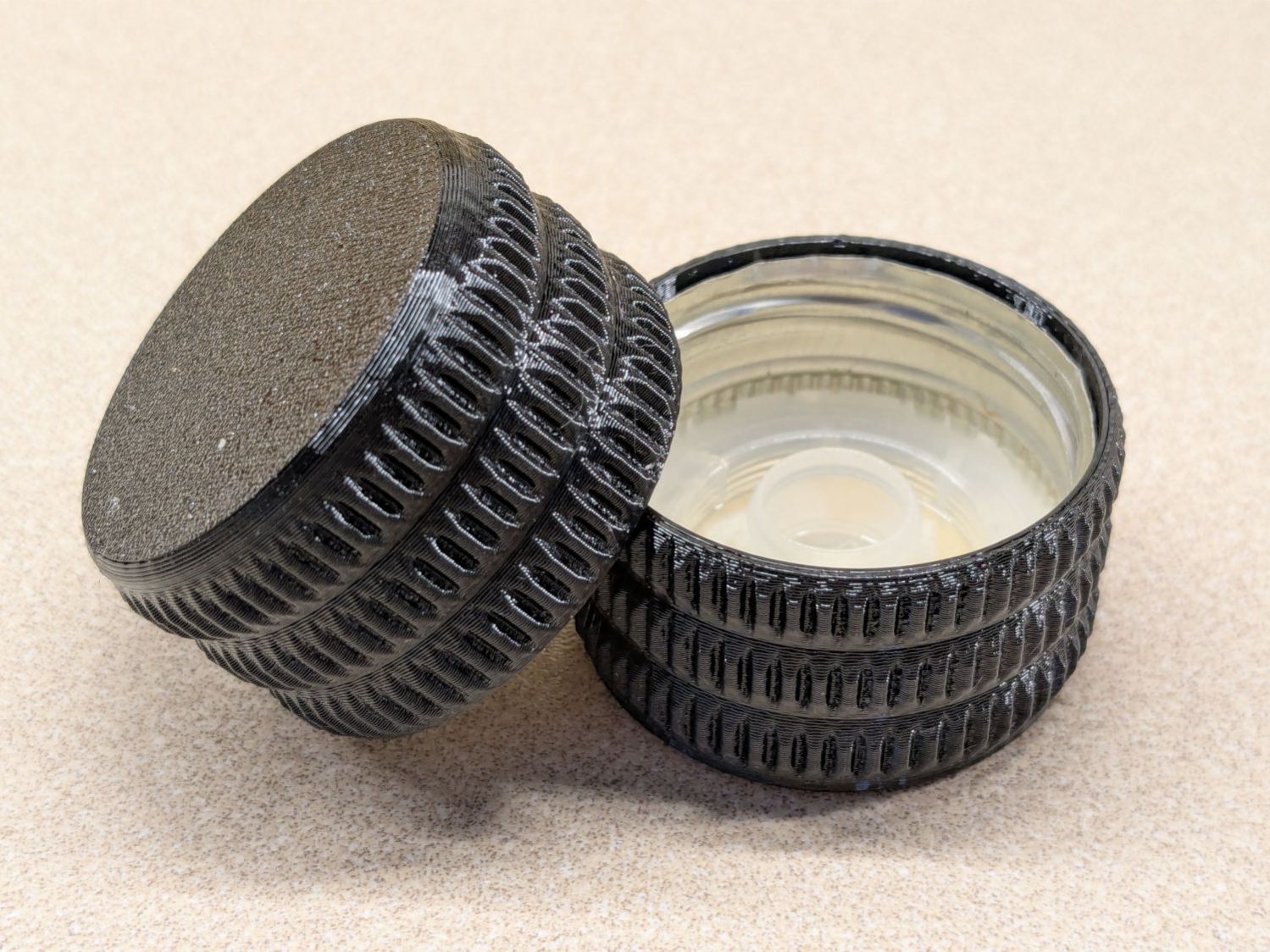
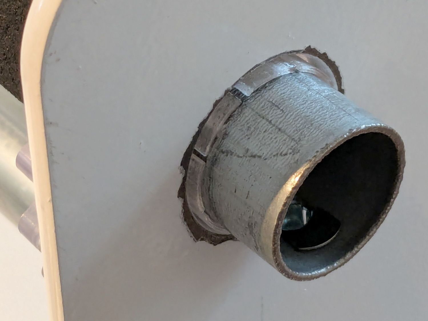
The tube OD is 28.7 mm (so it’s probably 1 inch EMT) and the plate hole ID is 31.2 mm (likely a scant 1-¼ inch punch), leaving barely a millimeter of clearance all around. I wanted to make a bearing from suitably slippery Delrin / acetal, but figured 3D printed PETG would suffice for at least while.
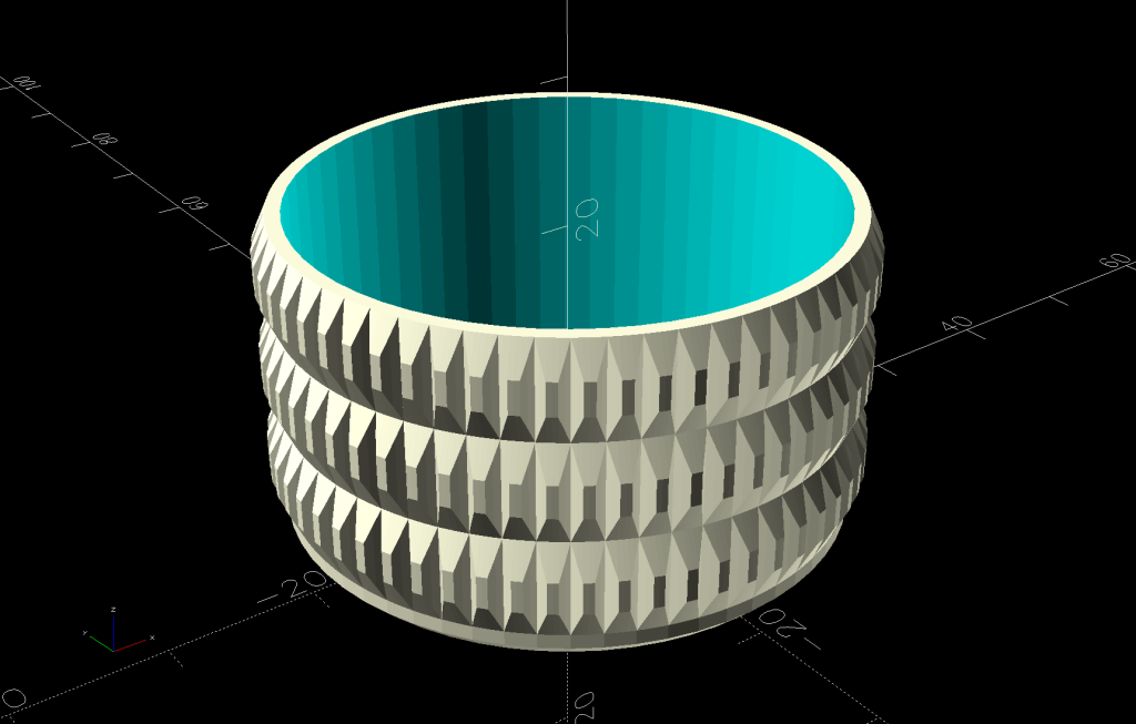
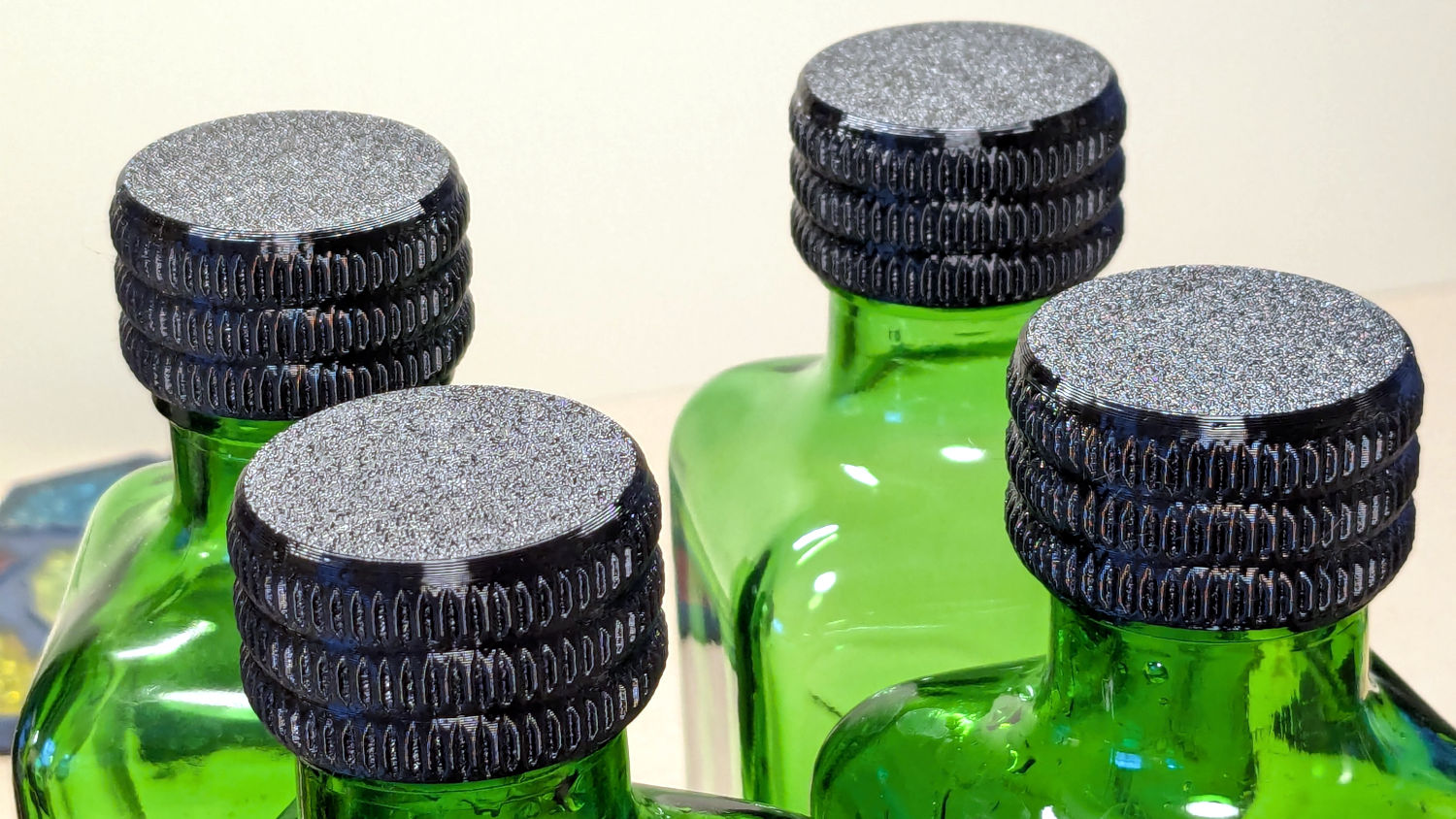
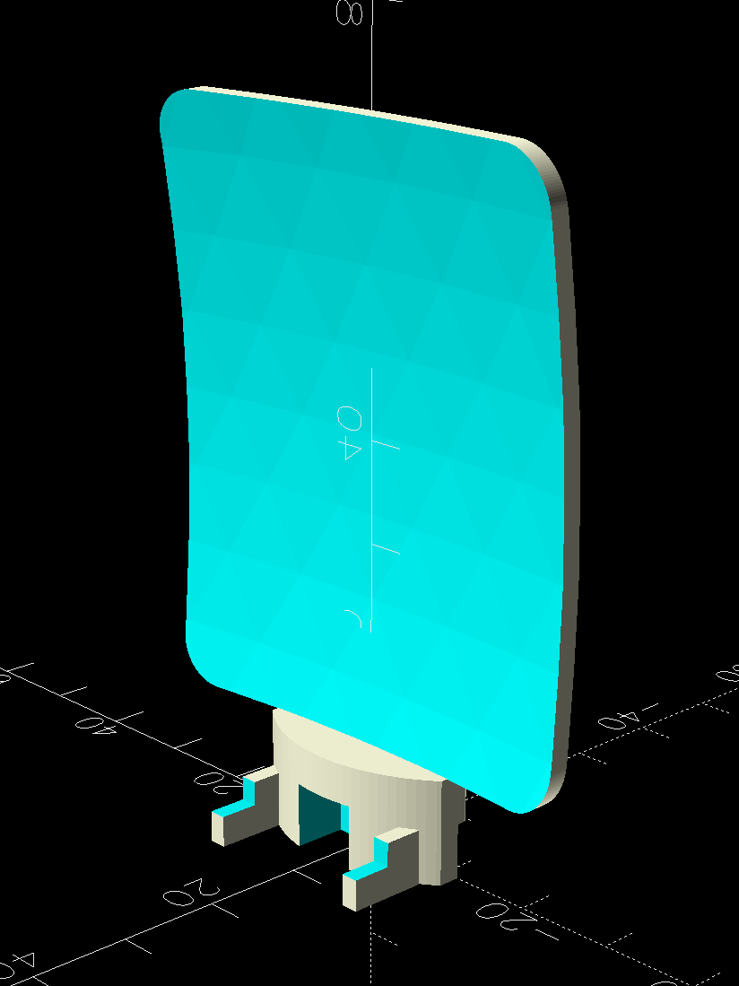
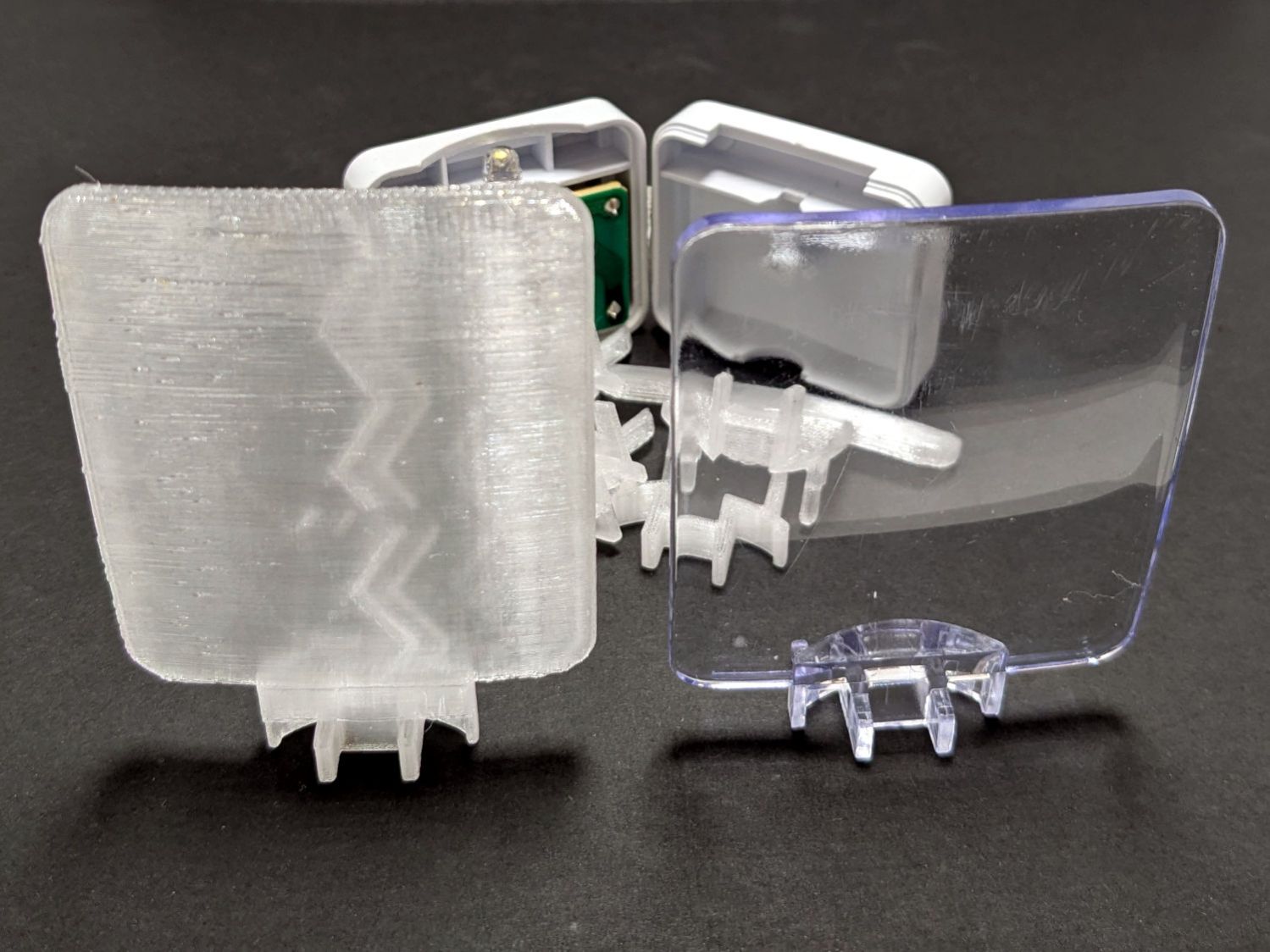
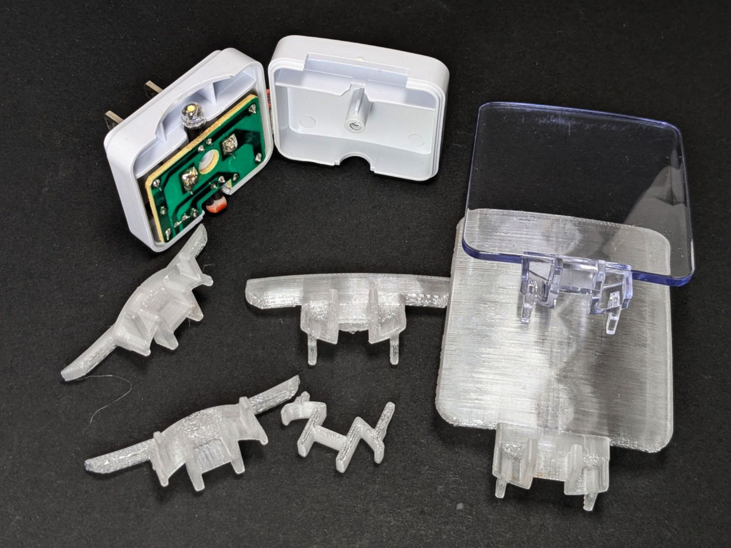
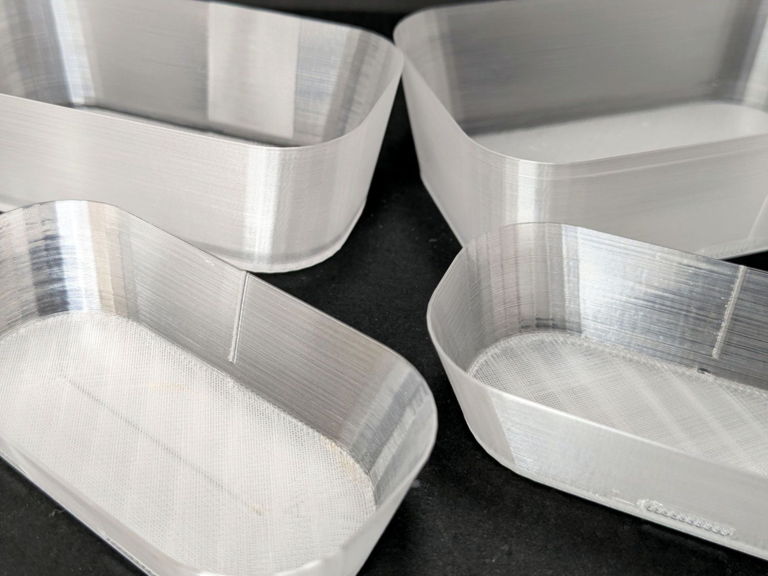
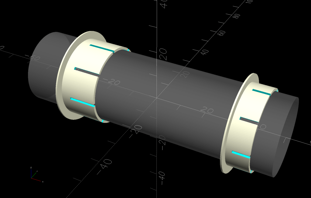
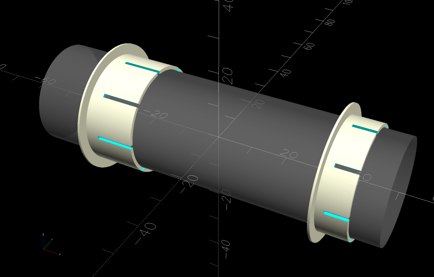
The proper term is “bushing“, because it has no moving parts:
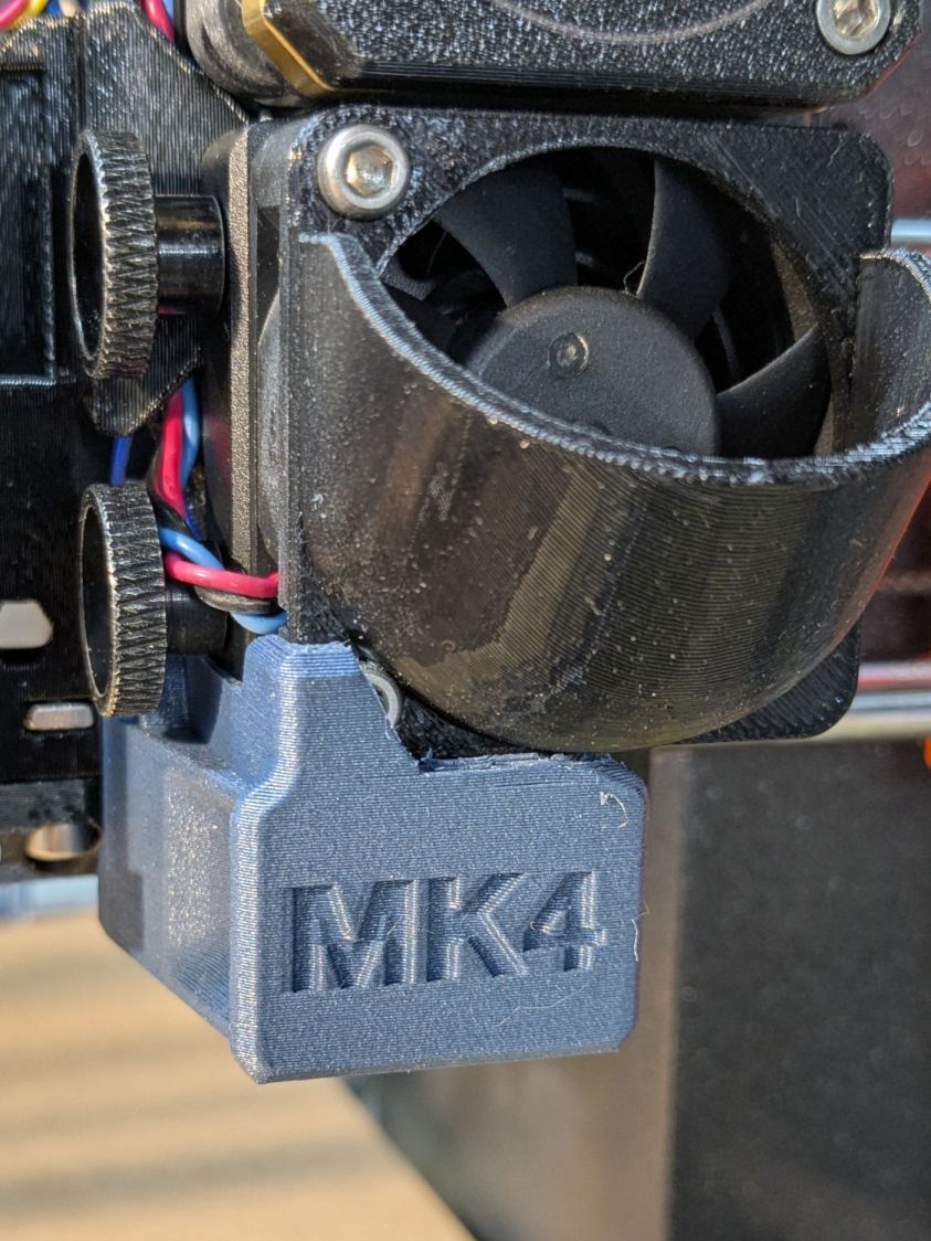
On the right side, the bushing rim must fit between the sprockets and the plate:

The spring-loaded pin holding the tube in place (visible on the inside bottom) sets the maximum length:
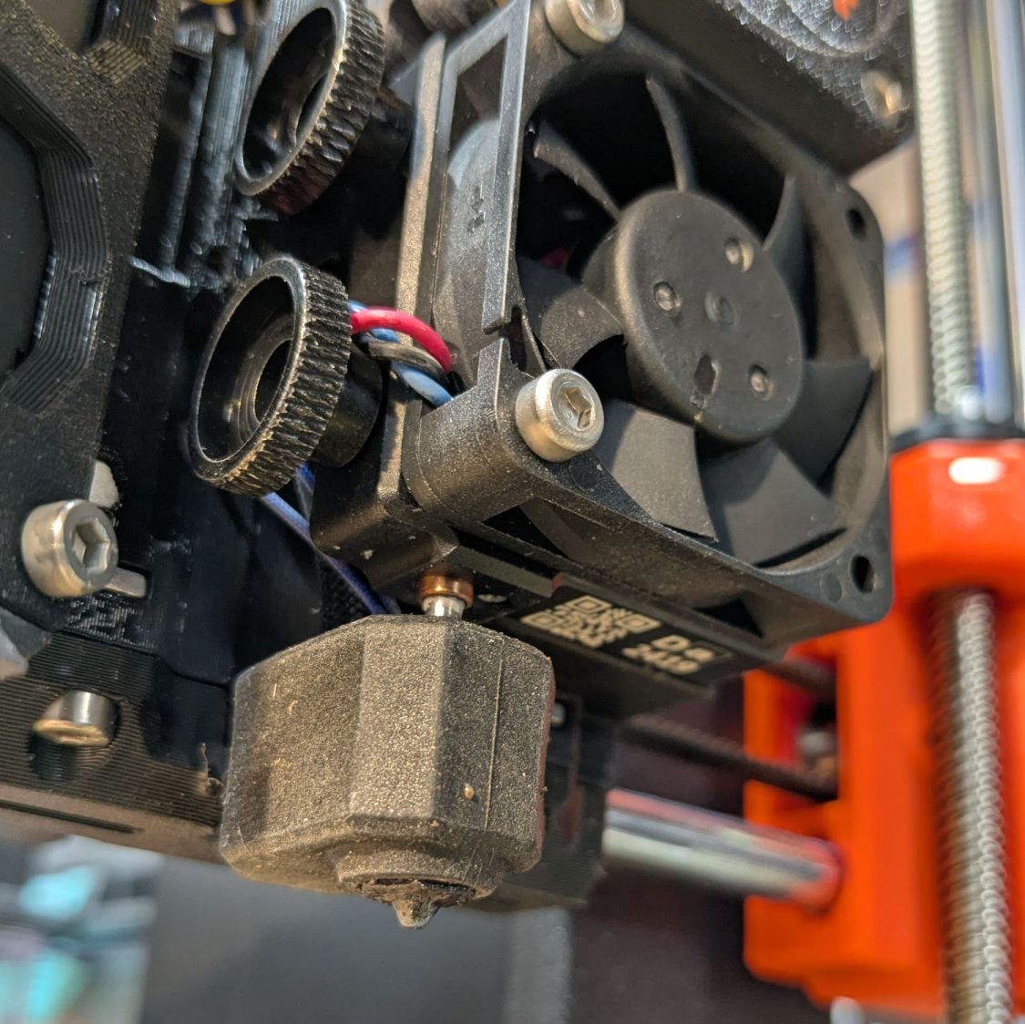
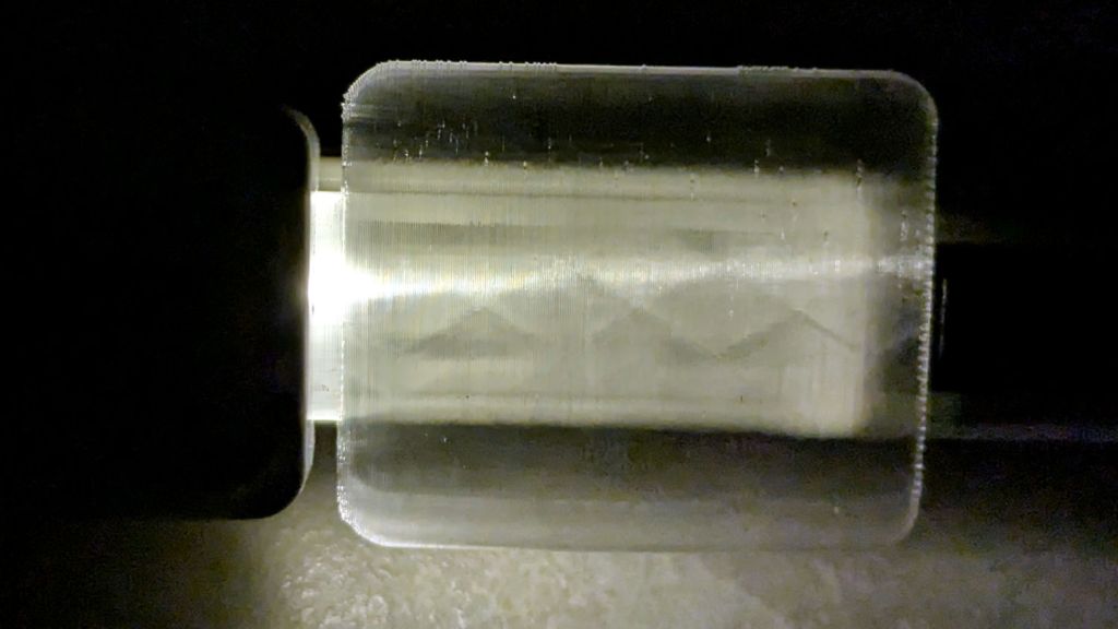
The left side has none of that, so I made the bushings a little longer:
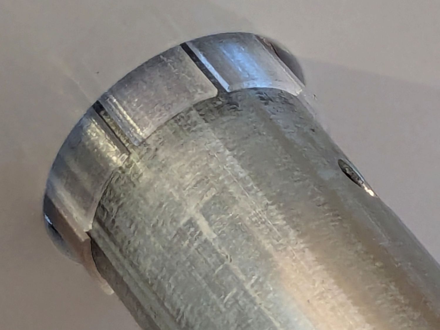
The left-side bushings will need a better design should normal back-and-forth sliding push them out of place.
A touch of silicone grease around the plate holes makes those bushings / bearings turn sooo smooth.
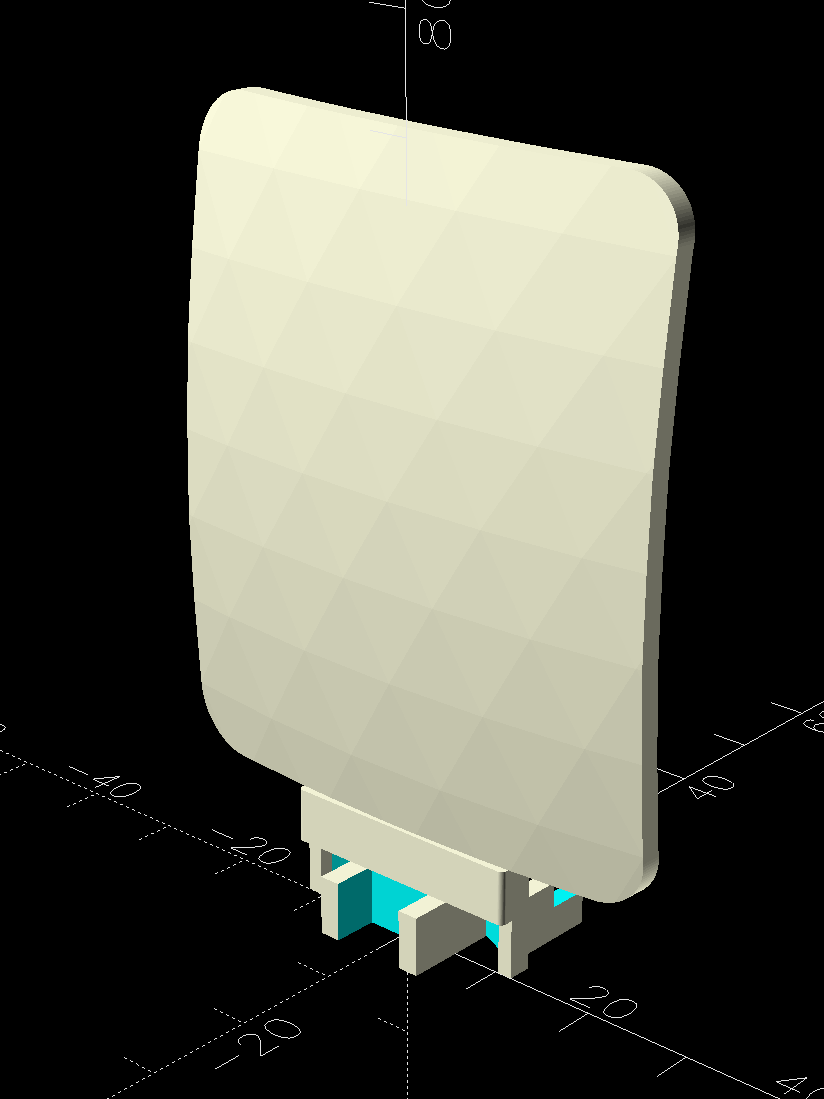
The OpenSCAD source code as a GitHub Gist:
| // Bearing sleeve for HQ Sixteen table rods | |
| // Ed Nisley – KE4ZNU | |
| // 2026-02-20 | |
| include <BOSL2/std.scad> | |
| Layout = "Show"; // [Show,Build] | |
| /* [Hidden] */ | |
| ID = 0; | |
| OD = 1; | |
| LENGTH = 2; | |
| HoleWindage = 0.2; | |
| Protrusion = 0.1; | |
| NumSides = 8*3*2*4; | |
| $fn=NumSides; | |
| Rod = [25.0,28.7,100.0]; // very short rod | |
| Sleeve = [Rod[OD] + 0.3,31.2 – 0.2,9.0]; // LENGTH = overall | |
| Rim = [Sleeve[ID],Sleeve[OD] + 6.0,0.6]; | |
| IdlerLength = 15.0; | |
| NumSlots = 2*4; | |
| Kerf = 1.0; | |
| Gap = 5.0; | |
| module Bearing(oal) { | |
| difference() { | |
| union() { | |
| tube(oal,id=Sleeve[ID],od=Sleeve[OD],anchor=BOTTOM); | |
| tube(Rim[LENGTH],id=Rim[ID],od=Rim[OD],anchor=BOTTOM); | |
| } | |
| for (a=[0:NumSlots-1]) | |
| zrot(a*360/NumSlots) | |
| up(oal/4 + Rim[LENGTH]) | |
| right(Sleeve[ID]/2) | |
| cuboid([Sleeve[OD],Kerf,oal],anchor=BOTTOM); | |
| } | |
| } | |
| //—– | |
| // Build things | |
| if (Layout == "Show") { | |
| color("Gray",0.5) | |
| xcyl(Rod[LENGTH],d=Rod[OD]); | |
| right(Rod[LENGTH]/3) | |
| yrot(90) | |
| Bearing(Sleeve[LENGTH]); | |
| left(Rod[LENGTH]/3) | |
| yrot(90) | |
| Bearing(IdlerLength); | |
| } | |
| if (Layout == "Build") { | |
| right(Rim[OD]/2 + Gap/2) | |
| Bearing(Sleeve[LENGTH]); | |
| left(Rim[OD]/2 + Gap/2) | |
| Bearing(IdlerLength); | |
| } |