Ed Nisley's Blog: Shop notes, electronics, firmware, machinery, 3D printing, laser cuttery, and curiosities. Contents: 100% human thinking, 0% AI slop.
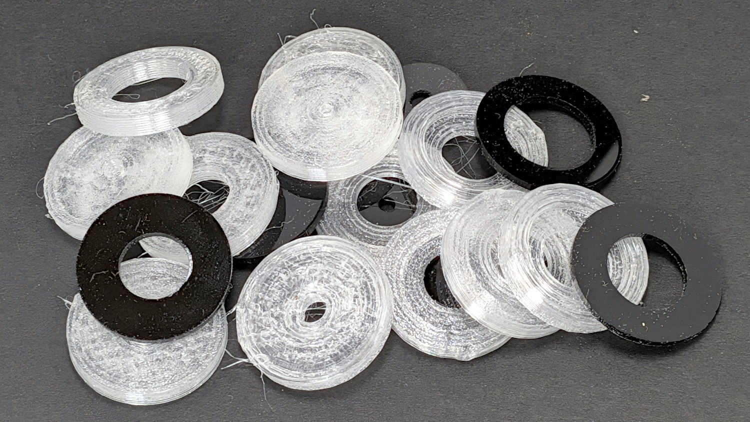
Mary wanted less pressure in the spray while watering her plants and I suggested replacing the nozzle’s washer with a flow restrictor:
Hose Nozzle Flow Restrictors – assembled
The 3D-printed TPU base is squishy enough to act as a hose washer:
Hose Nozzle Flow Restrictor Base – solid model
A 1.5 mm thick acrylic orifice plate snapped into the opening takes advantage of the laser cutter’s precision:
Hose Nozzle Flow Restrictors – LightBurn layout
For lack of anything smarter, the holes have areas that are powers-of-two smaller than the nozzle’s 14.2 mm = 158 mm² internal passage: the hole labeled 8 is 158/256 mm² = 0.62 mm² → 0.9 mm diameter.
Rather than figuring each hole’s diameter, just divide the previous diameter by √2 or rescale it by 100%/√2, which LightBurn can evaluate directly in its Numeric Edits fields. The as-cut holes are larger than their nominal size by about 0.1 mm, but any errors that might cause are definitely in the nature of fine tuning while watering the plants.
The nozzle’s Shower pattern (on the left in the picture) has a 6.8 L/minute = 110 ml/s flow through an ordinary garden hose washer. The four smallest aperture plates produced these flows:
Hose Nozzle Flow Restrictors – flow vs dia
The flow should scale with the square of the aperture diameter, which I could bully those points into suggesting, but the measurement accuracy produced by filling a gallon jug while tapping my phone’s stopwatch doesn’t justify anything fancier.
The two smallest apertures reduce the Shower pattern to a very gentle spray requiring far too long to put enough water on the plants. Mary now uses an old plastic sprinkler head with enough holes to produce a dense spray with very little force, with the flow set by fifty feet of PEX pipe running across the width of the house from the town water inlet to the hose bib.
It was a fun exercise and I learned a little more about printing TPU and fitting acrylic parts therein:
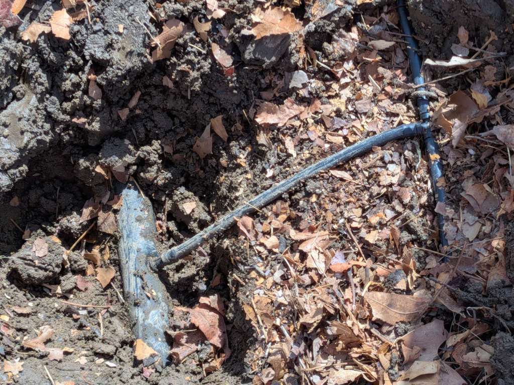
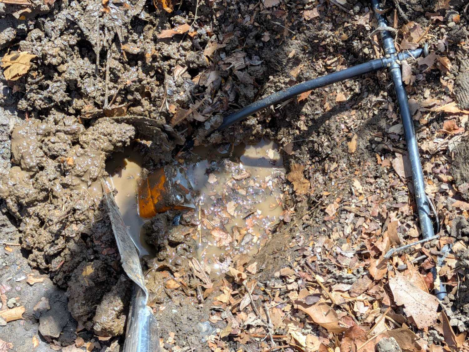
A large gooey puddle helped isolate a leak in the Dripworks main line pipe running the length of Mary’s Vassar Farms plot:
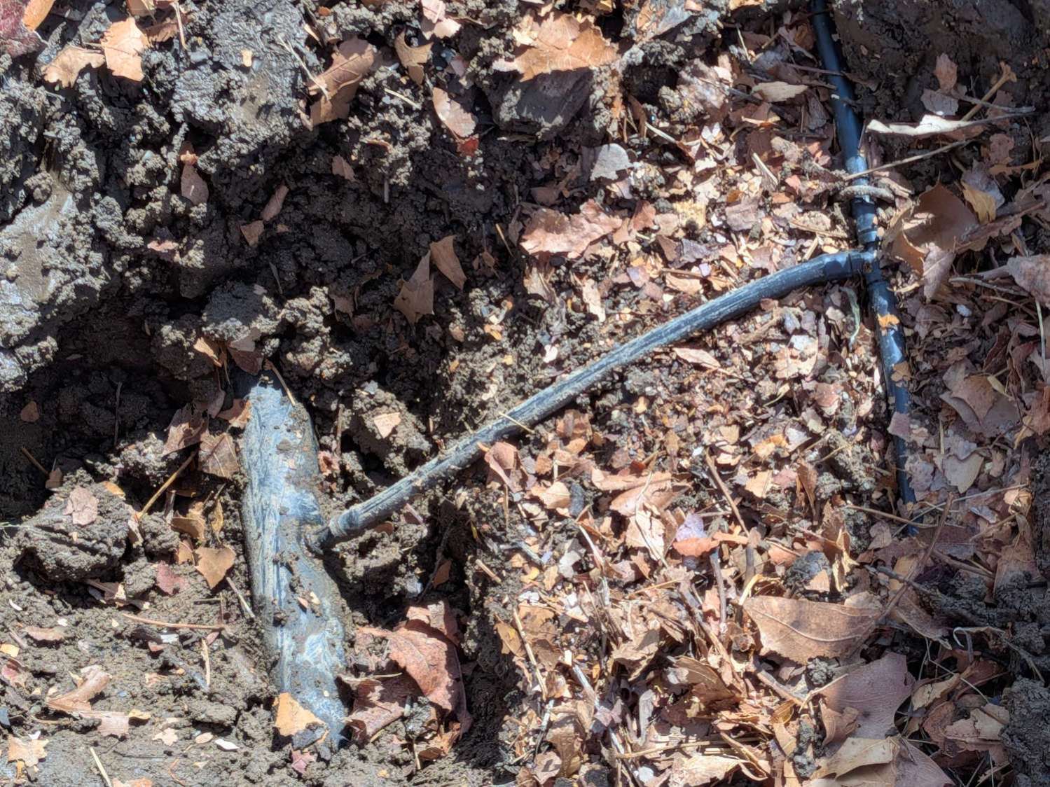
Dripworks Mainline clamp – injured hose joint
Much of the tubing between the transfer barb in the buried pipe and the cross coupling lies on the surface, where it’s subject to missteps. This being just a few feet inside the garden gate, it’s no surprise enough missteps caused the barb to no longer seal properly.
You’re supposed to wrap silicone tape while keeping its surface clean, which is obviously impossible in a hole rapidly filling with water draining from the plumbing but the clamp presses the tape firmly against the pipe and seals the leak.
There is, I regret to say, an 8-32 stainless steel washer lost somewhere deep in the muck.
I punched a new barb into the pipe with slightly longer tubing to the cross fitting, in the hope it’ll be more resilient.
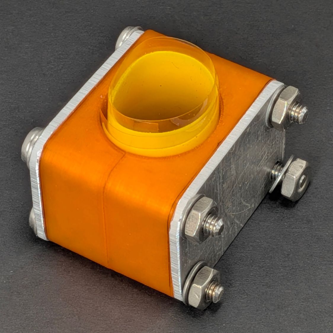
Another clamp with its silicone tape snippet stands ready for duty:
Dripworks Mainline Pipe Clamp – assembled
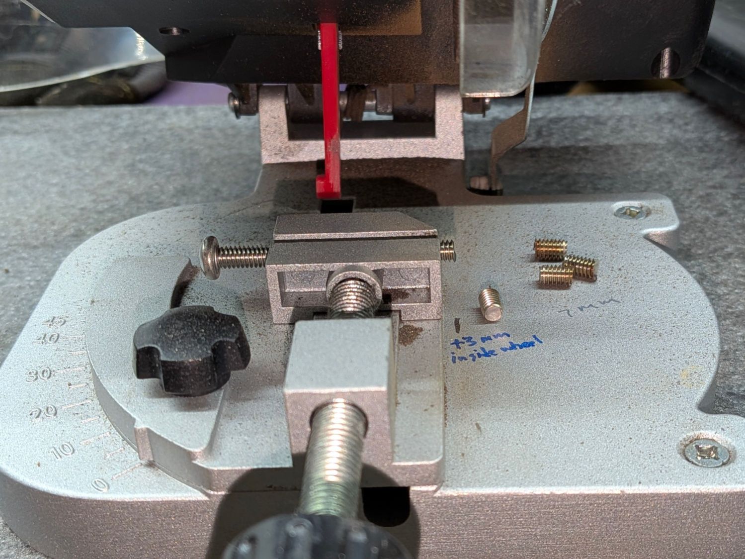
For the record, the Micromark Cutoff Saw has a 3 mm offset between the side of the vise and the left edge of the blade:
Micromark abrasive cutoff – work offset
I still lack a Round Tuit for improving that vise.
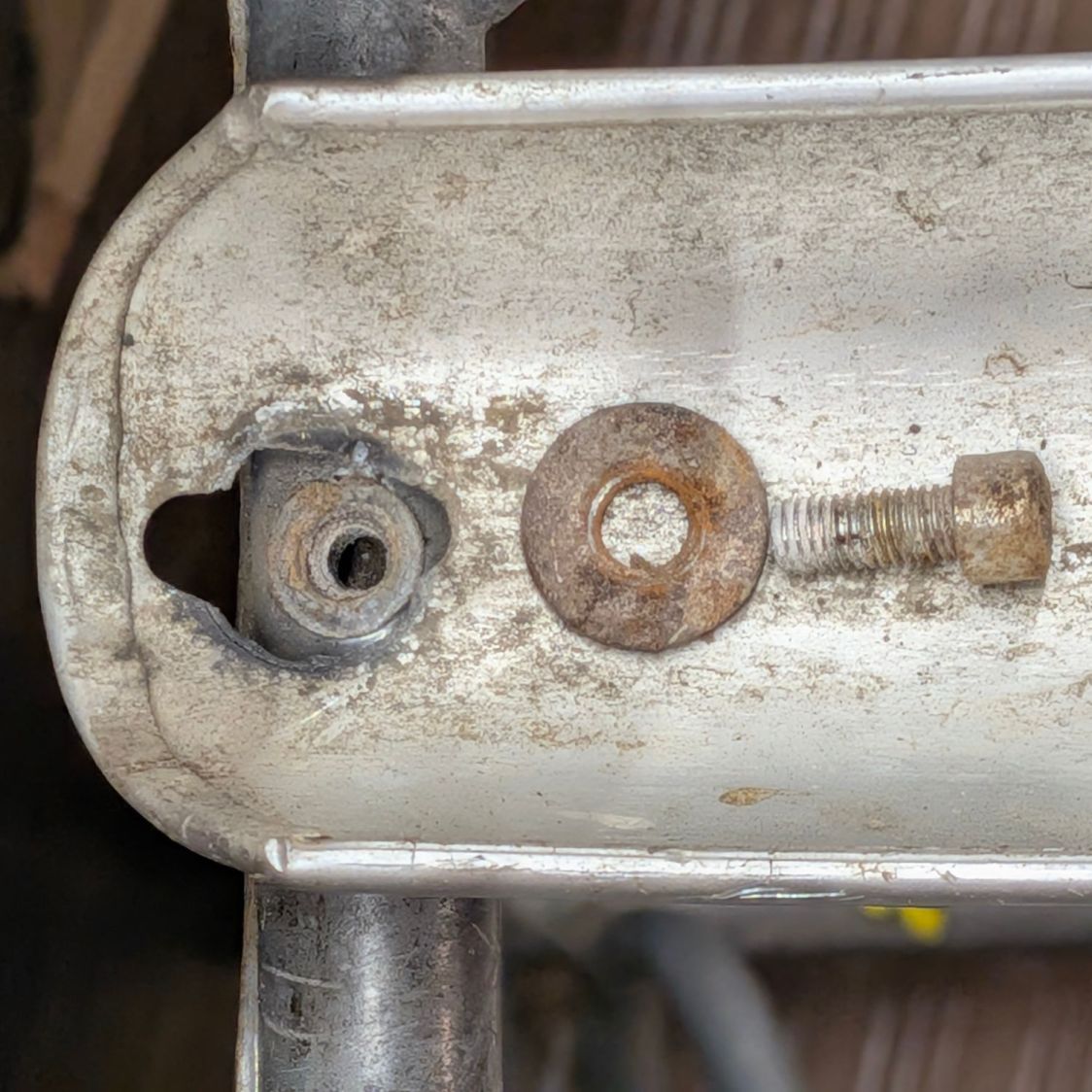
I eventually tracked a distressingly loud rattle from the BOB Yak trailer to a fender mount failure:
BOB Yak Trailer fender front mount – aluminum fatigue
The screw clamped the round aluminum fender between two flat washers (the other of which has been touring the workbench). The hole in the aluminum started as a screw slot and eventually fretted away around the edge of the washers, leaving a trapped fragment to fall out as I loosened the screw.
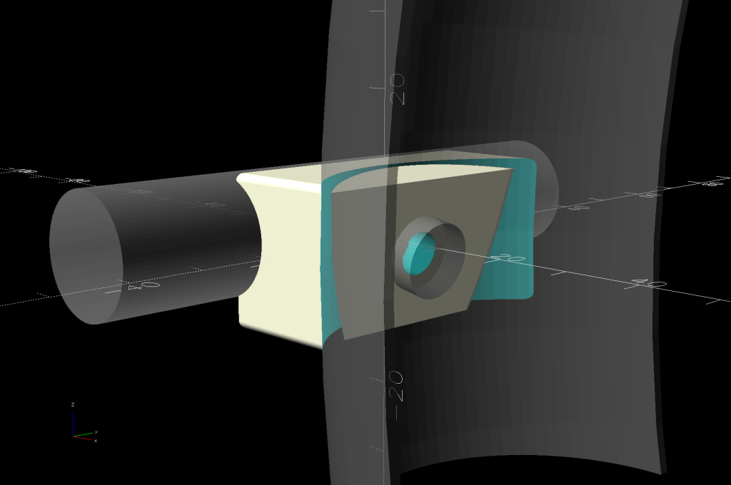
As before, a bit of math conjures a chunky mount from the vasty digital deep:
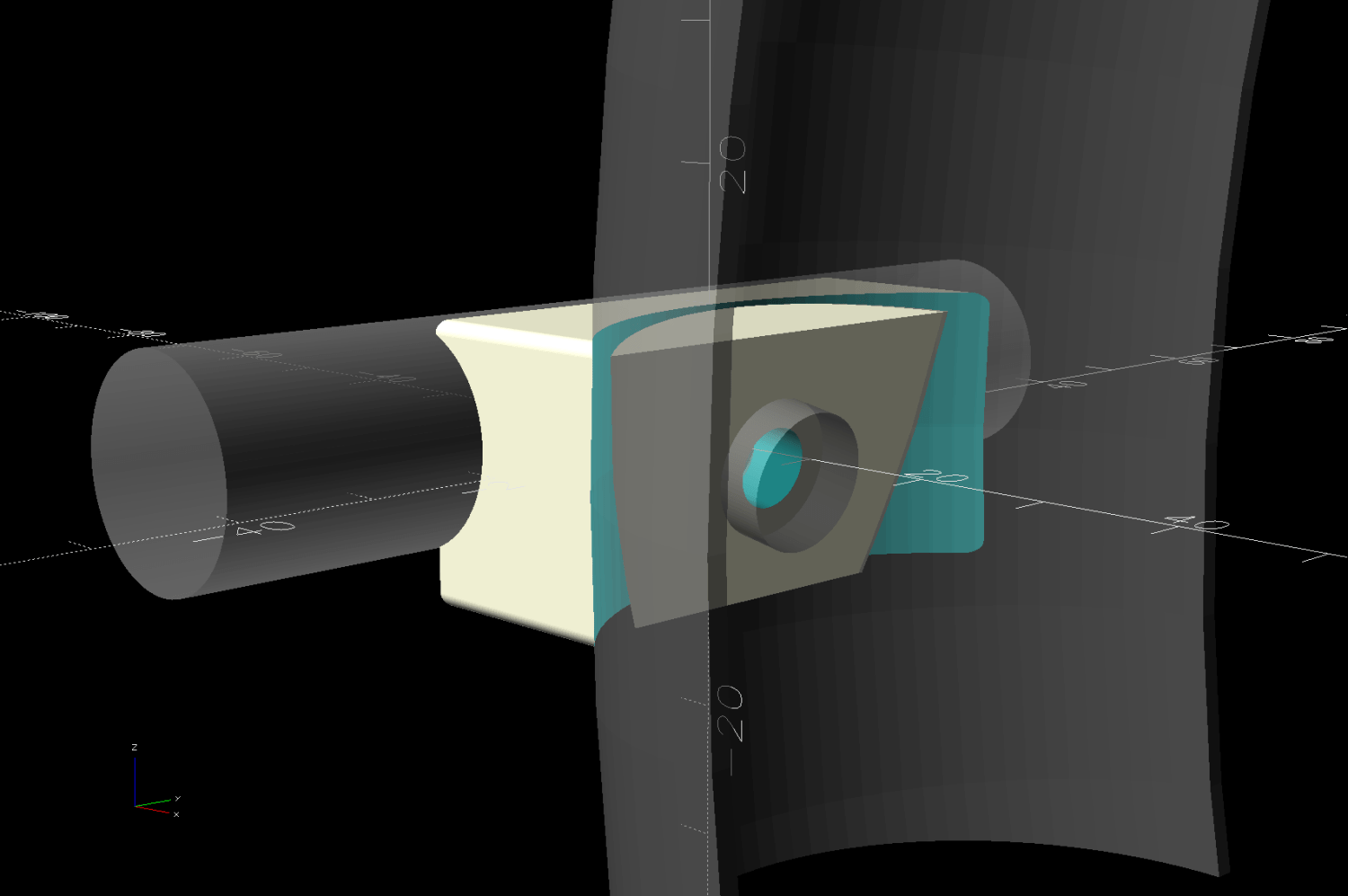
Fender front mount – solid model – Show view
The first iteration didn’t have the hole for the threaded insert angled downward at 10°, but it’s easier to make better measurements with a “pretty close” prototype. I’m reasonably sure the angle is a glitch due to hand-brazing the frame tubes, but we’ll never know.
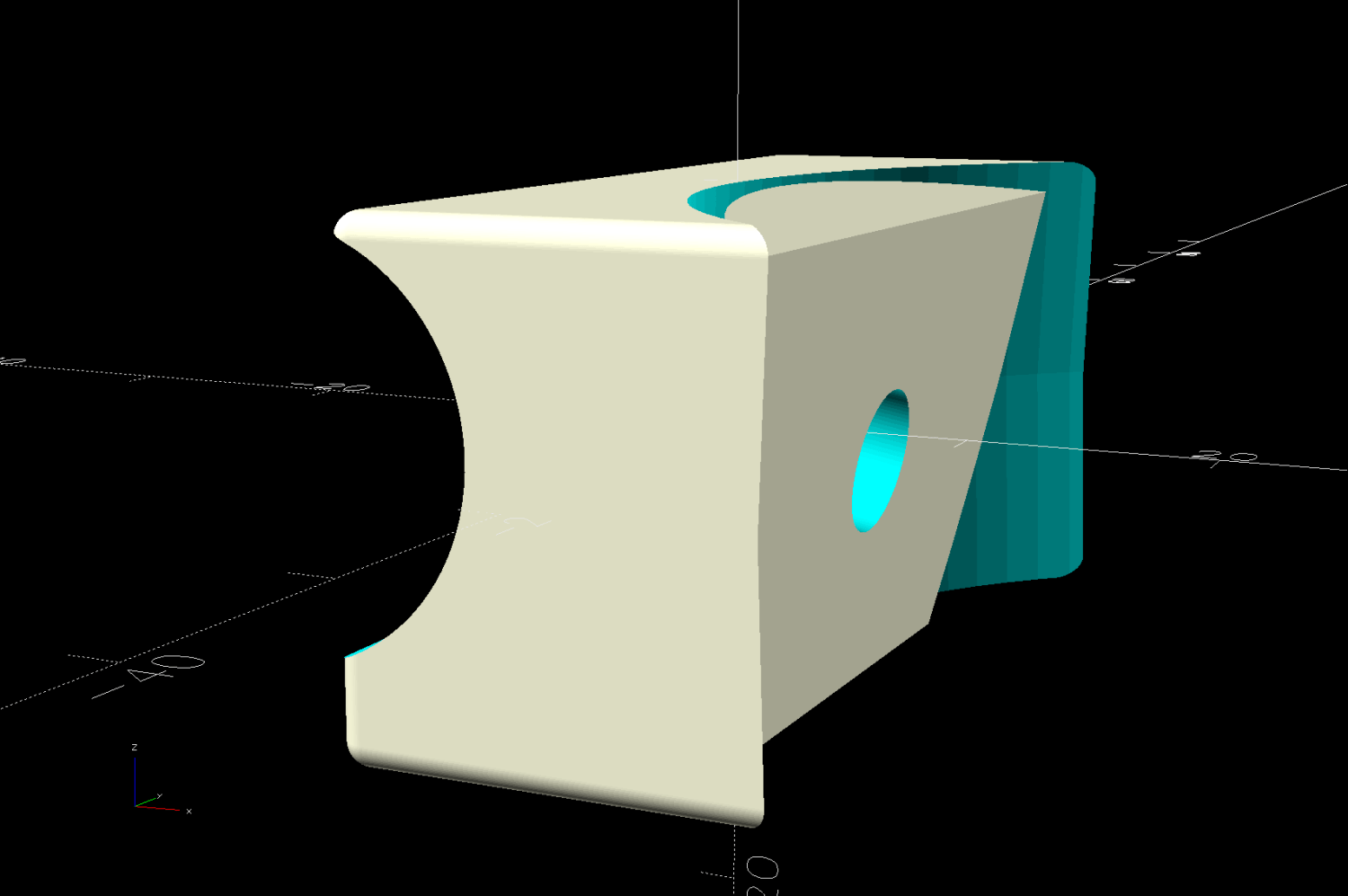
The inner plate angles to match the insert, thus keeping the screw & washer perpendicular to the surface:
Fender front mount – solid model – Mounts view
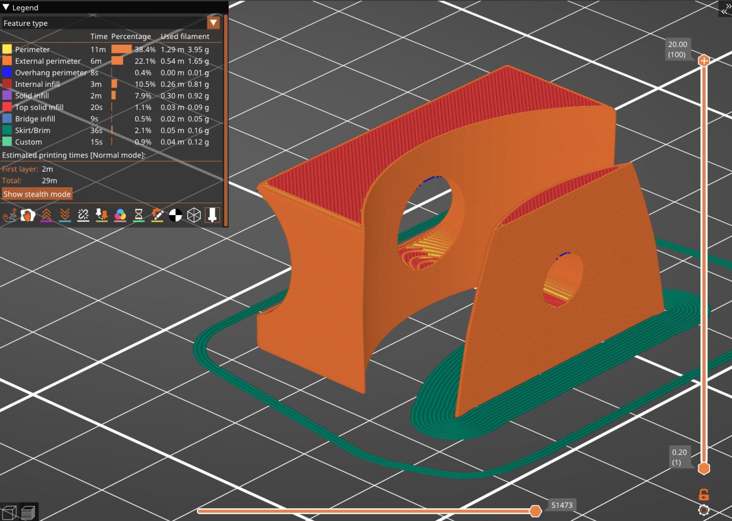
A brim around that chip of plastic ensures a good grip on the platform:
BOB Yak Trailer – fender front mount – PrusaSlicer preview
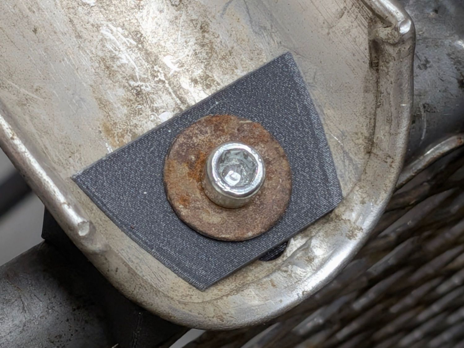
I suppose rounding the corners would make it prettier:
BOB Yak Trailer fender front mount – inner plate
The original screw was slightly too short, so that’s a shiny replacement from the Drawer o’ Random M5 Screws. If I ever have occasion to go in there again, I’ll use a button head screw, although there’s certainly enough clearance:
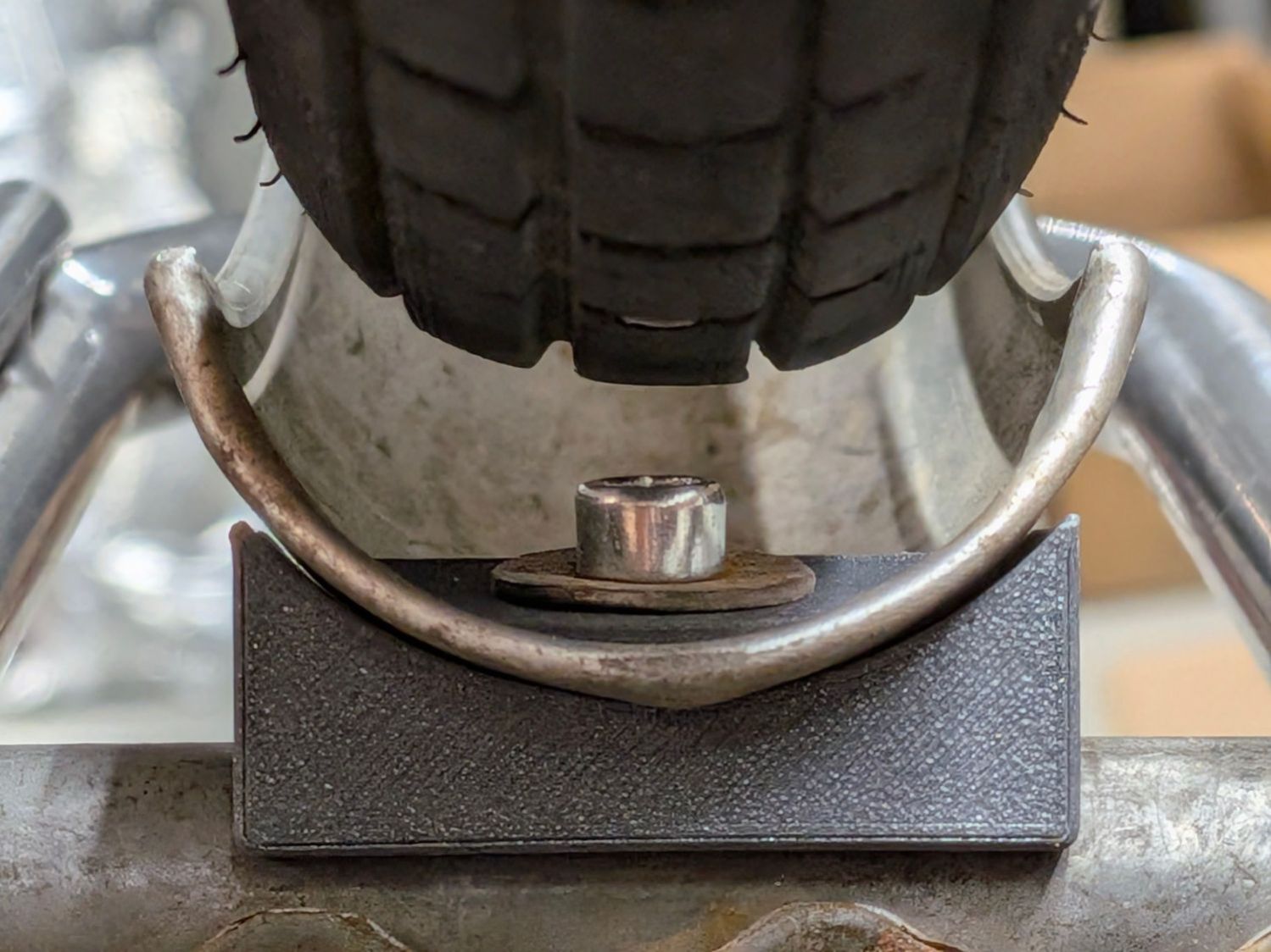
BOB Yak Trailer fender front mount – tire clearance
From the top, the gray PETG-CF looks like it grew there:
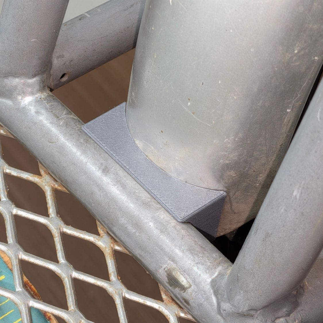
BOB Yak Trailer fender front mount – installed
I figured the mount’s radius by feeding measurements into the chord equation and assuming the overall curve is circular; the radius came out slightly too large, which likely won’t make much difference.
This file contains hidden or bidirectional Unicode text that may be interpreted or compiled differently than what appears below. To review, open the file in an editor that reveals hidden Unicode characters.
Learn more about bidirectional Unicode characters
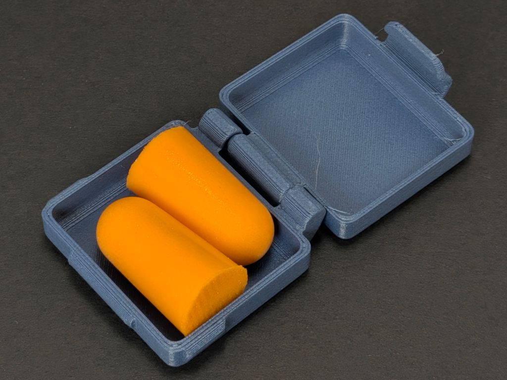
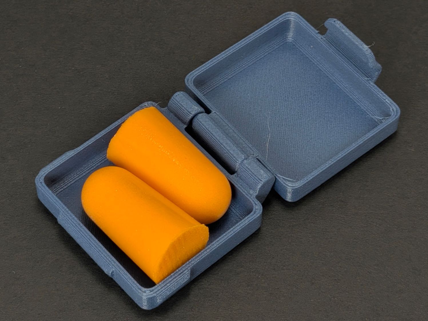
A no-assembly-needed earplug case from Printables will be more easily found in Mary’s purse than the previous small bag:
Earplug case
That’s the “grippy bits” version of the model, which really is easier to open than the straight-sided version.
I printed a few more, loaded them with earplugs, and put them where they may come in handy. In retrospect, I should have used clear PETG to show off the retina-burn plugs.
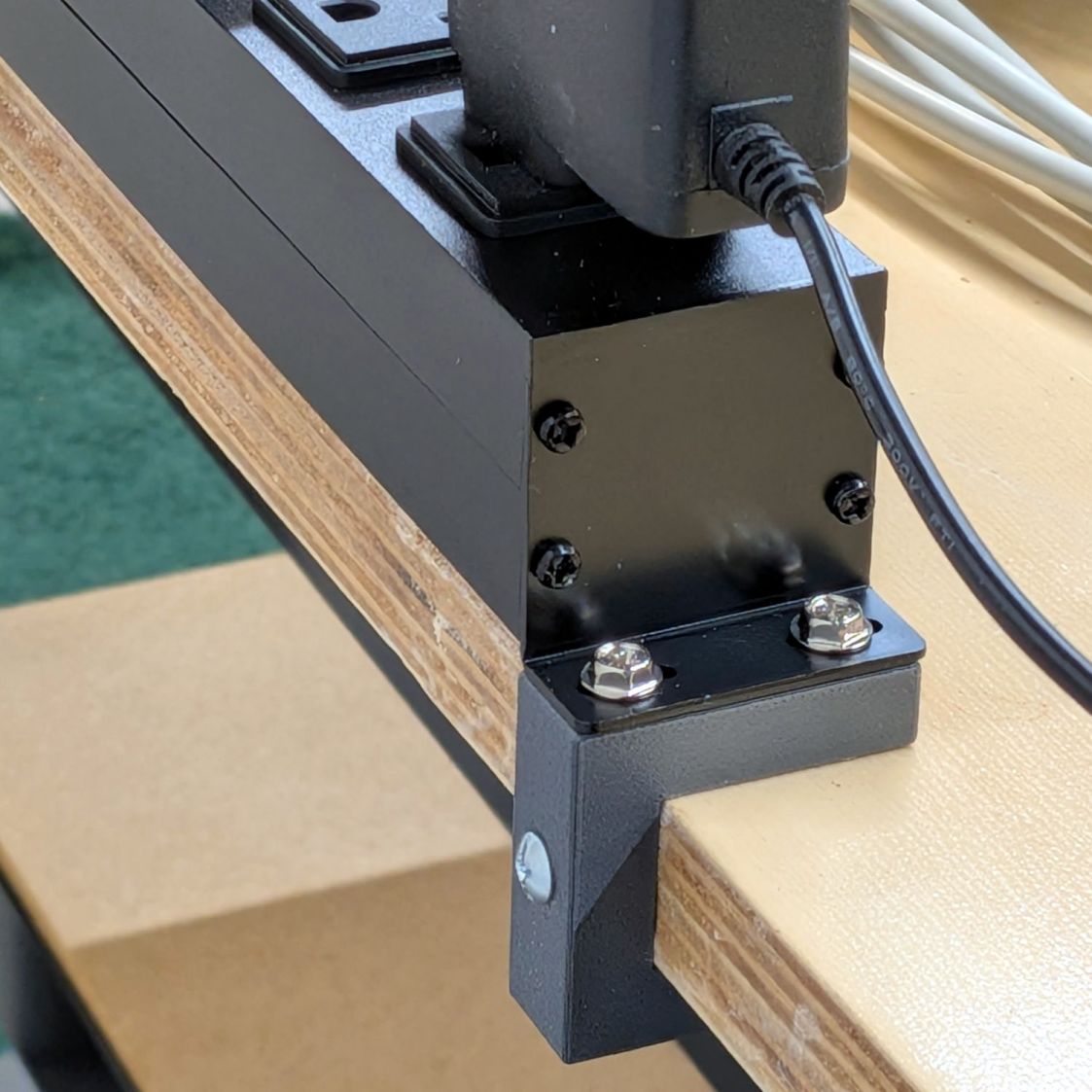
A spate of tidying-up led to mounting an outlet strip along the back of a bench:
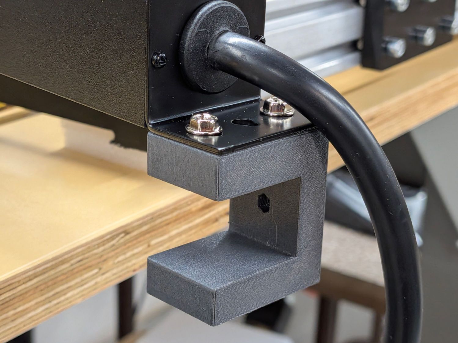
Outlet Bench Mount – installed
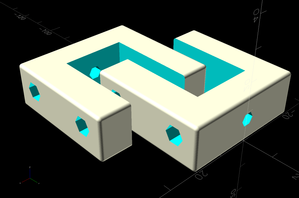
Rather than drill holes into the top of the bench for those screws, they fit into M4 brass inserts heat-staked into the brackets:
Outlet Bench Mount – show view
The holes for those inserts aren’t centered side-to-side on the brackets, because the screw holes aren’t centered on the bent-steel angles forming the outlet strip endplates.
The bottom arm on the brackets probably isn’t necessary, but they kept the outlet strip from crawling away while I match-drilled two holes for the screws into the side of the benchtop.
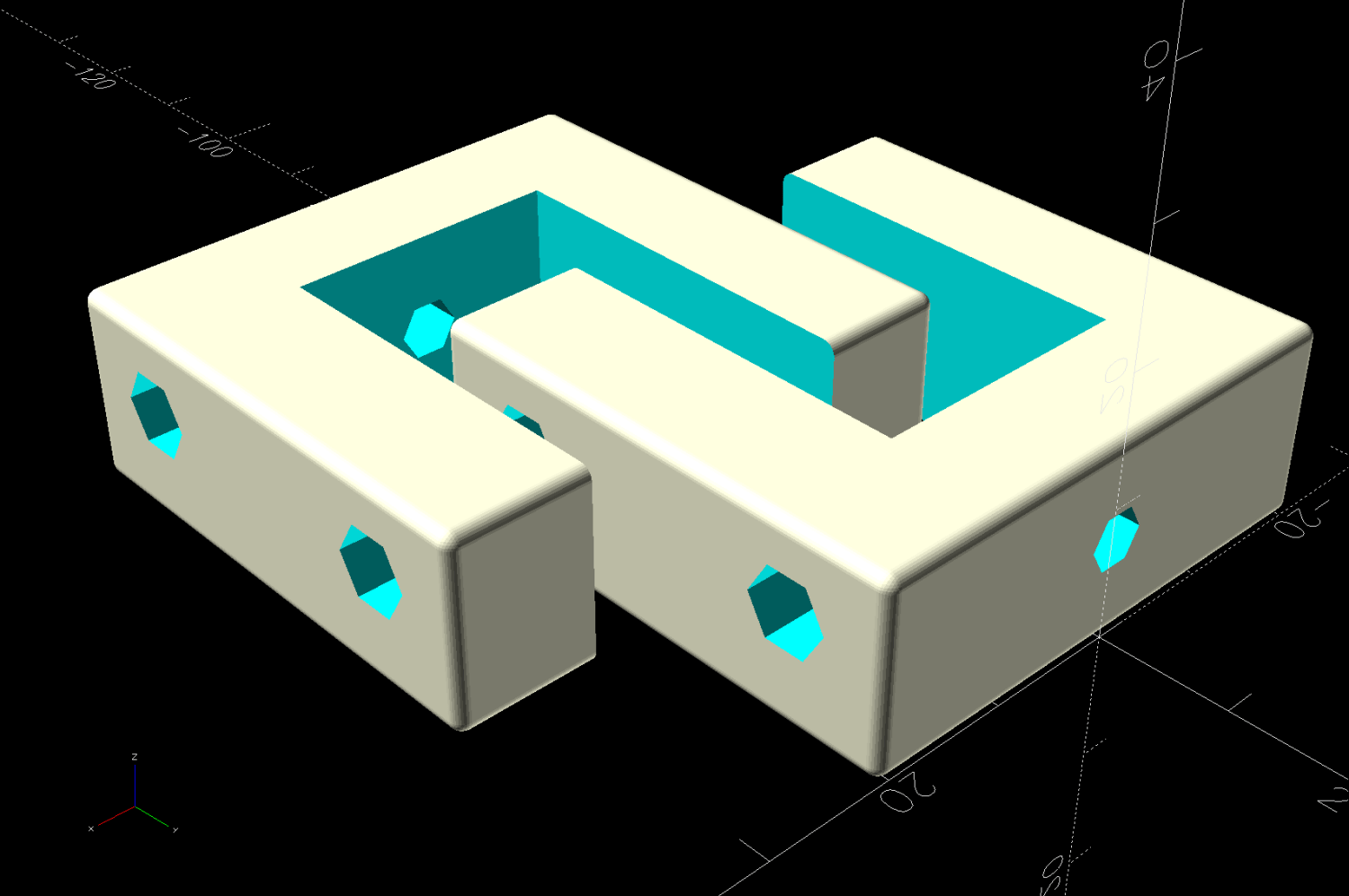
For obvious reasons, the brackets print on their sides:
Outlet Bench Mount – build view
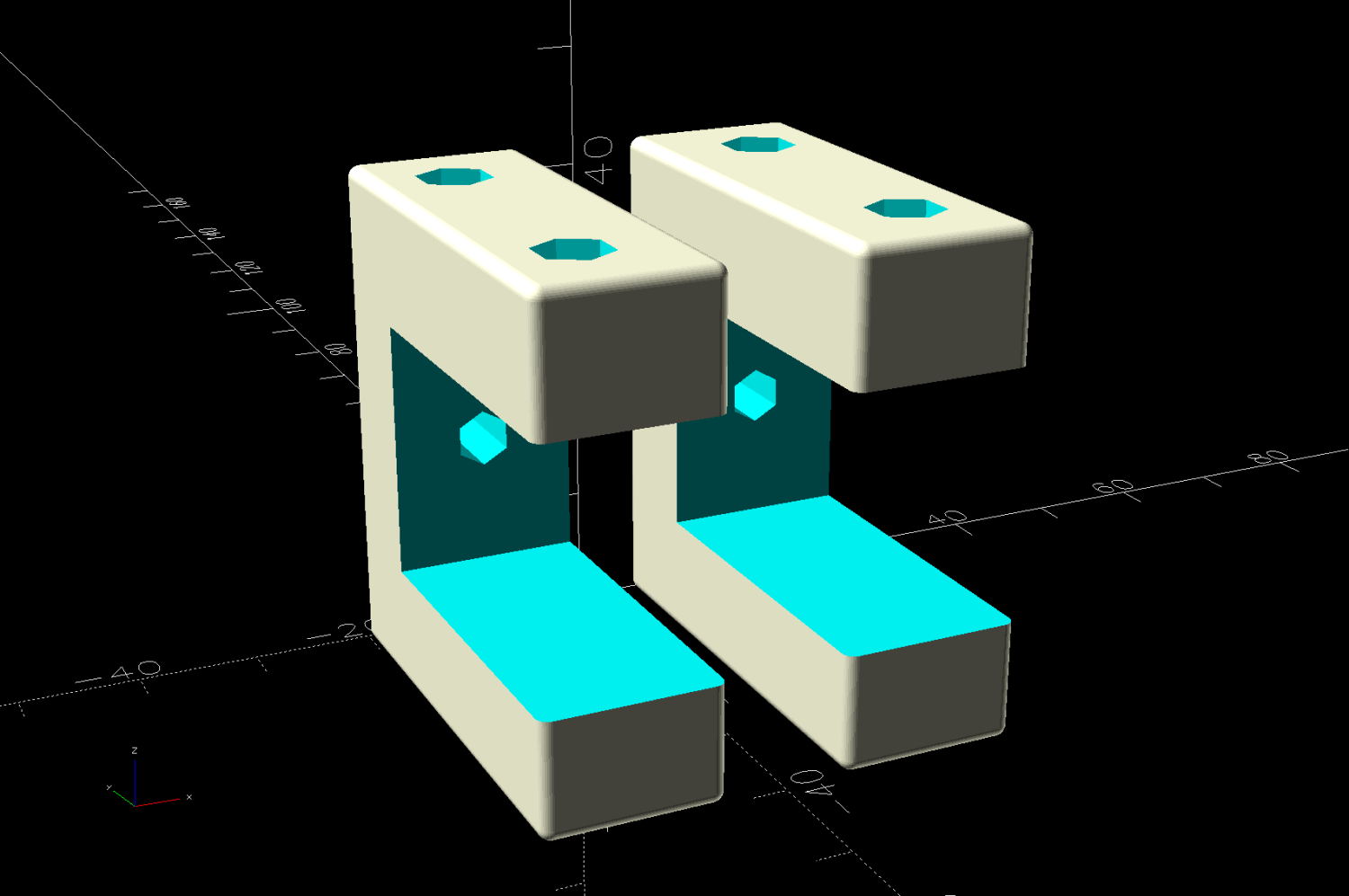
Another outlet strip from a different manufacturer is, of course, different, but changing three parameters in the OpenSCAD program summons a different bracket from the vasty digital deep:
Outlet Bench Mount – different brand
Parametric modeling and a 3D printer are exactly the right hammers for the job …
This file contains hidden or bidirectional Unicode text that may be interpreted or compiled differently than what appears below. To review, open the file in an editor that reveals hidden Unicode characters.
Learn more about bidirectional Unicode characters
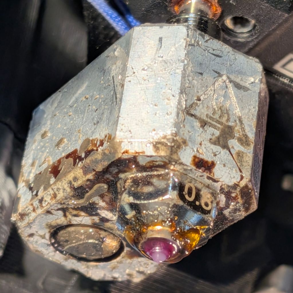
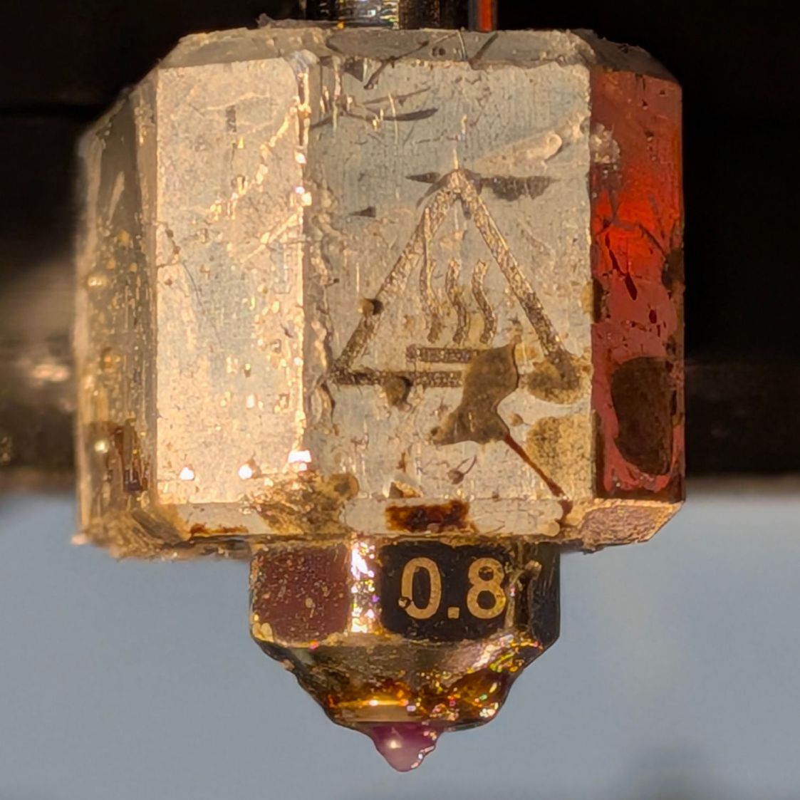
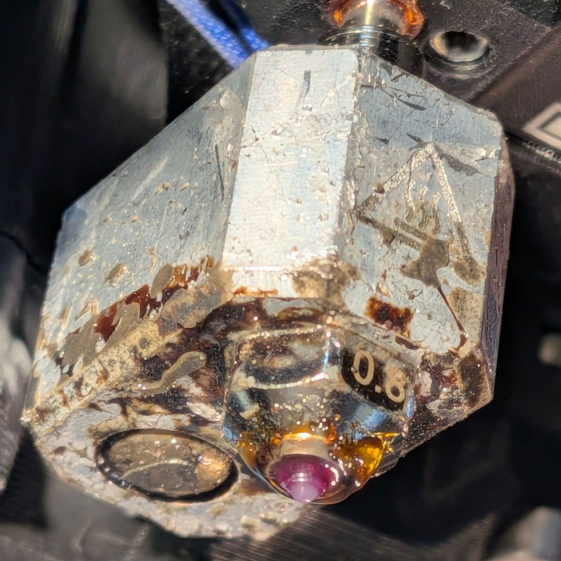
The aluminum block doesn’t look nearly as awful as these pictures suggest; those plastic smears serve as reminders of a few previous printing mishaps.
The nozzle is a 0.8 mm Durozzle with a ruby tip suitable for abrasive filaments like PETG-CF, although this is gooey squishy “natural” TPU:
Prusa MK4 hot end – 0.8 mm Durozzle ruby – bottom
The first patio table foot test piece in TPU had terrible adhesion to the Textured Sheet, which I eventually tracked down to an excessively thick first layer. Given that the MK4 homes the axes and performs mesh bed leveling probes over the build area, this was difficult to believe, particularly because it had never been a problem with the Prusa 0.4 mm ObXidian hardened steel nozzle.
More poking around showed some of the plastic drool left on the outside of the nozzle from the previous print session (as shown in the two pictures above) could remain hardened or at least “not squishy” despite the nozzle being heated before homing and mesh probing. Because probing depends on having the nozzle touch the platform, anything between the nozzle and the steel sheet will raise the Z=0 position and cause all the layers to be too high.
As far as I can tell, ruby has a thermal coefficient around 40 W/m·K, roughly the same as steel. Both are considerably lower than the 200-ish W/m·K for the aluminum block surrounding the nozzle tube, suggesting most of whatever temperature gradient there may be occurs between the heater and the nozzle, not in the nozzle.
While puzzling that out, I noticed the nozzle heated to only 160 °C prior to homing and probing, which seemed low for a filament calling for 230 to 250 °C during printing. Ordinary PETG heated to 170 °C, so something was different.
More puzzling showed the Start G-Code section of the printer’s Custom G-Code sets the home / probe temperature, herein reformatted for readability:
I had set up the eSun TPU 95A filament parameters based on Prusa’s TPU definition. I eventually discovered that definition includes the text MBL160 in its Notes section, which satisfies the regex in the first ternary operator:
Which sets the temperature to 10 °C below the first layer temperature, which I had set to 230 °C, so the probing now occurs at 220 °C.
I am not making this up.
Although that may be a bit too hot, the drool on the nozzle softens nicely and smashes flat during probing, thus solving the immediate problem and, without further ado, produced good round and square TPU feet.
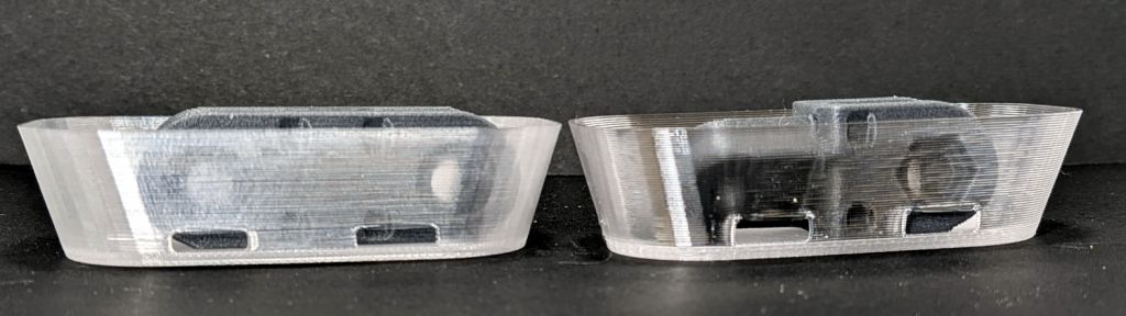
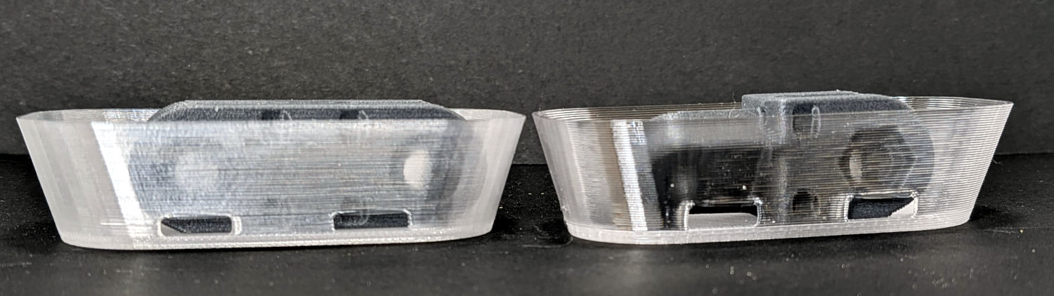
In addition to printing bendyobjects with TPU, the 0.8 mm nozzle 3D-prints PETG into thin walls with better transparency than the default 0.4 mm nozzle:
Clear PETG – 0.4 vs 0.8 mm nozzle – side view
The wall is now 1.0 mm thick, rather than 0.6 mm, and is much closer to being transparent. Those gray links from the RPi camera mount inside the dishes help show the difference.
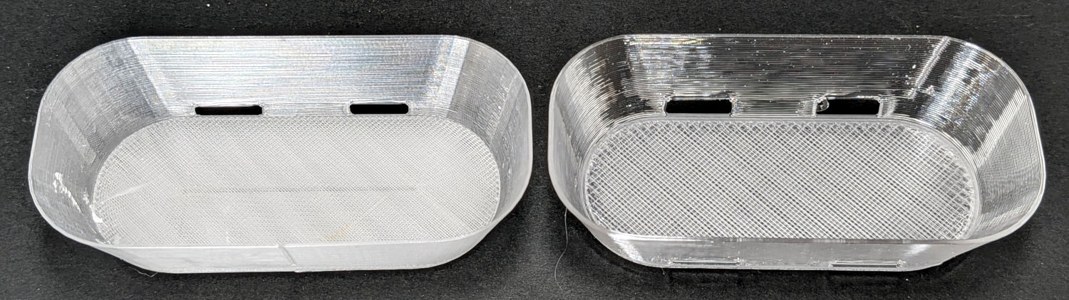
The 2.0 mm thick base plate is also more transparent, but mostly just reveals the 0.4 mm thick infill layers:
Clear PETG – 0.4 vs 0.8 mm nozzle – top view
More study is needed, even if we already have far more soap dishes than strictly necessary.