Ed Nisley's Blog: Shop notes, electronics, firmware, machinery, 3D printing, laser cuttery, and curiosities. Contents: 100% human thinking, 0% AI slop.
One of Mary’s garden neighbors recently started biking, she recommended he needed a helmet mirror, and I handed her a spare from the Bag o’ Mirrors:
Helmet Mirror Ball Mount – on helmet
So I built another one:
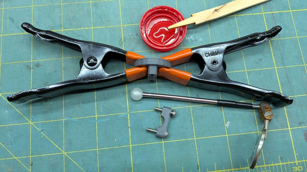
Helmet Mirror Ball Mount – epoxy clamping
Fortunately, the Bag also had that (slightly rusted) mirror with a drilled ball, so all I needed was a new printed mount with two brass inserts and screws.
Now we have two spares against future need:
Helmet Mirror Ball Mount – ready spares
They’re much better than the old yellow Az-El mount, but I couldn’t have made the ball mounts without that experience.
Both versions outlasted all the commercial versions we’ve had over the decades, so that’s a 3D printing success story right there.
It being once again time to tweak the mini-lathe’s cross slide and compound backlash …
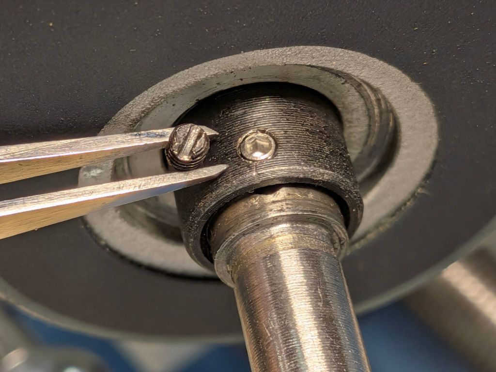
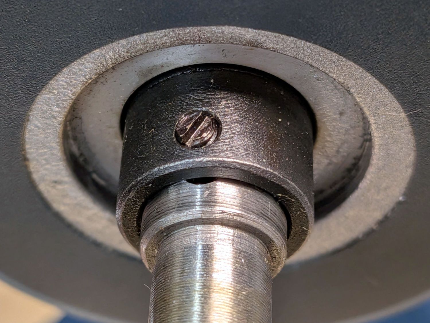
The M3 slotted setscrew locking the cross slide’s DRO collar to the feed screw shaft had come loose:
Mini-lathe – DRO slotted setscrew
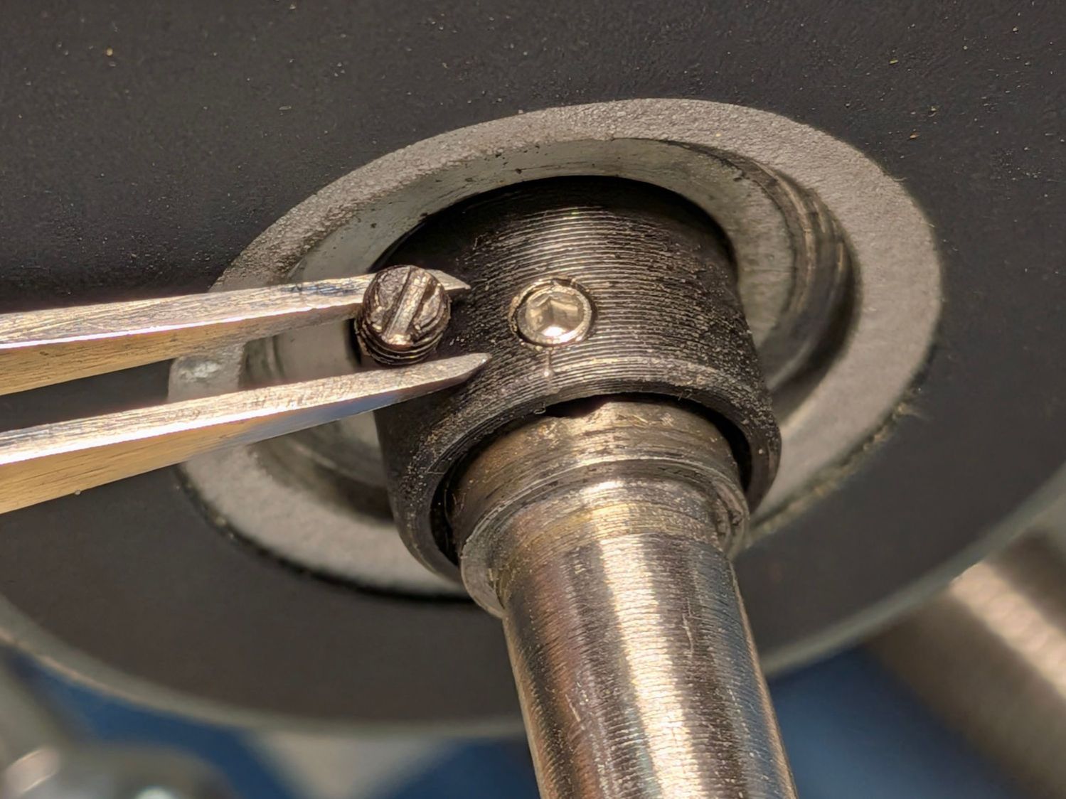
Although it has a cone point, presumably to center the slot in the feed screw, an M3 cup point hex setscrew works just fine:
Mini-lathe – DRO hex setscrew
A hex socket is much easier to tighten securely.
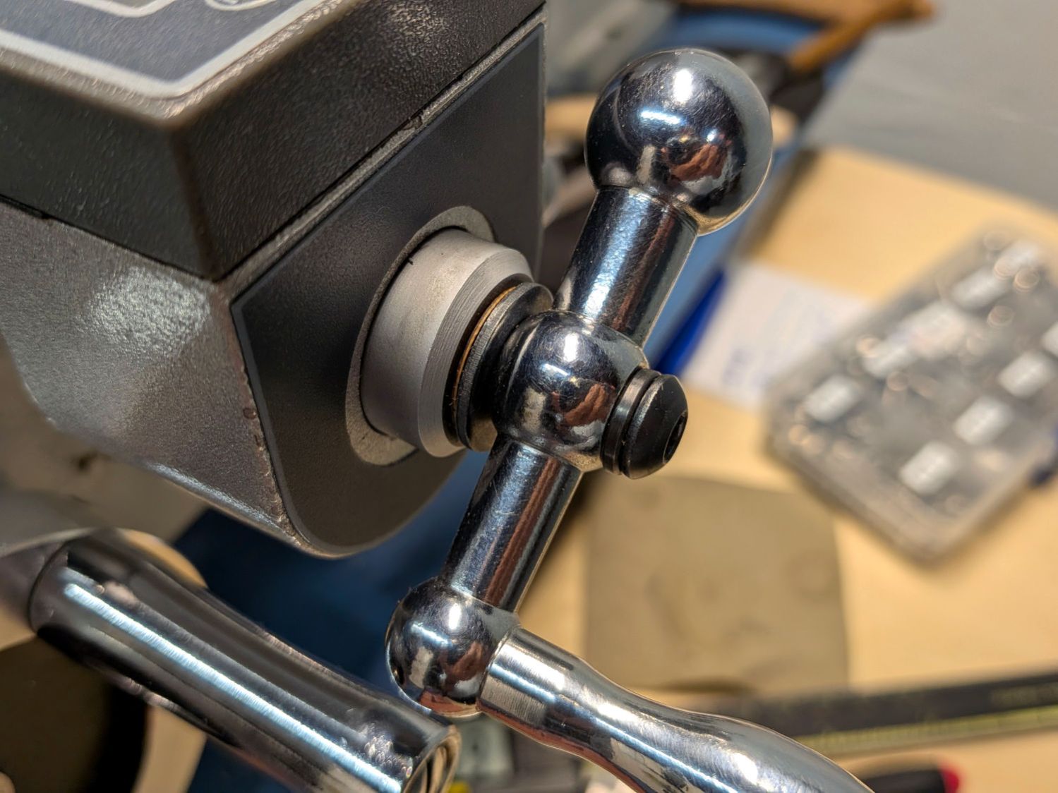
The handle sits against a black washer that looks like it should rest against the aluminum spacer covering the DRO shaft, but it doesn’t. Contrary to what I originally thought, that gap doesn’t contribute to the backlash (given a tight setscrew!), but a filler shim makes it look less like an afterthought:
Mini-lathe – cross slide handle shim
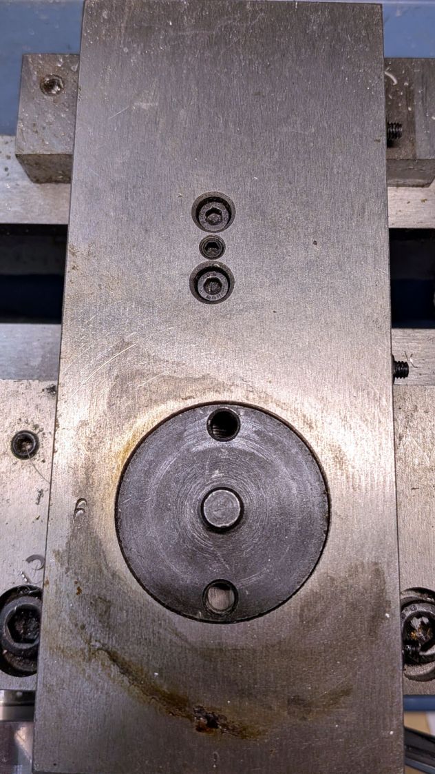
What does contribute to the backlash is a loose adjusting screw holding the follower nut against the feed screw:
Mini-lathe – cross slide backlash screws
The mini-lathe manual (page 17) and online references give the tedious process required to adjust the two cap screws and the setscrew to remove (nearly all of) the backlash. While I had the screws out, I took the opportunity to dribble oil through the cap screw holes onto the feed screw along as much of its length as was reachable.
Adjusting the gib screws is also a good idea, as is renewing the oil along the ways.
With all that done, the cross slide moves easily without slop and the backlash is a tolerable 0.1 mm.
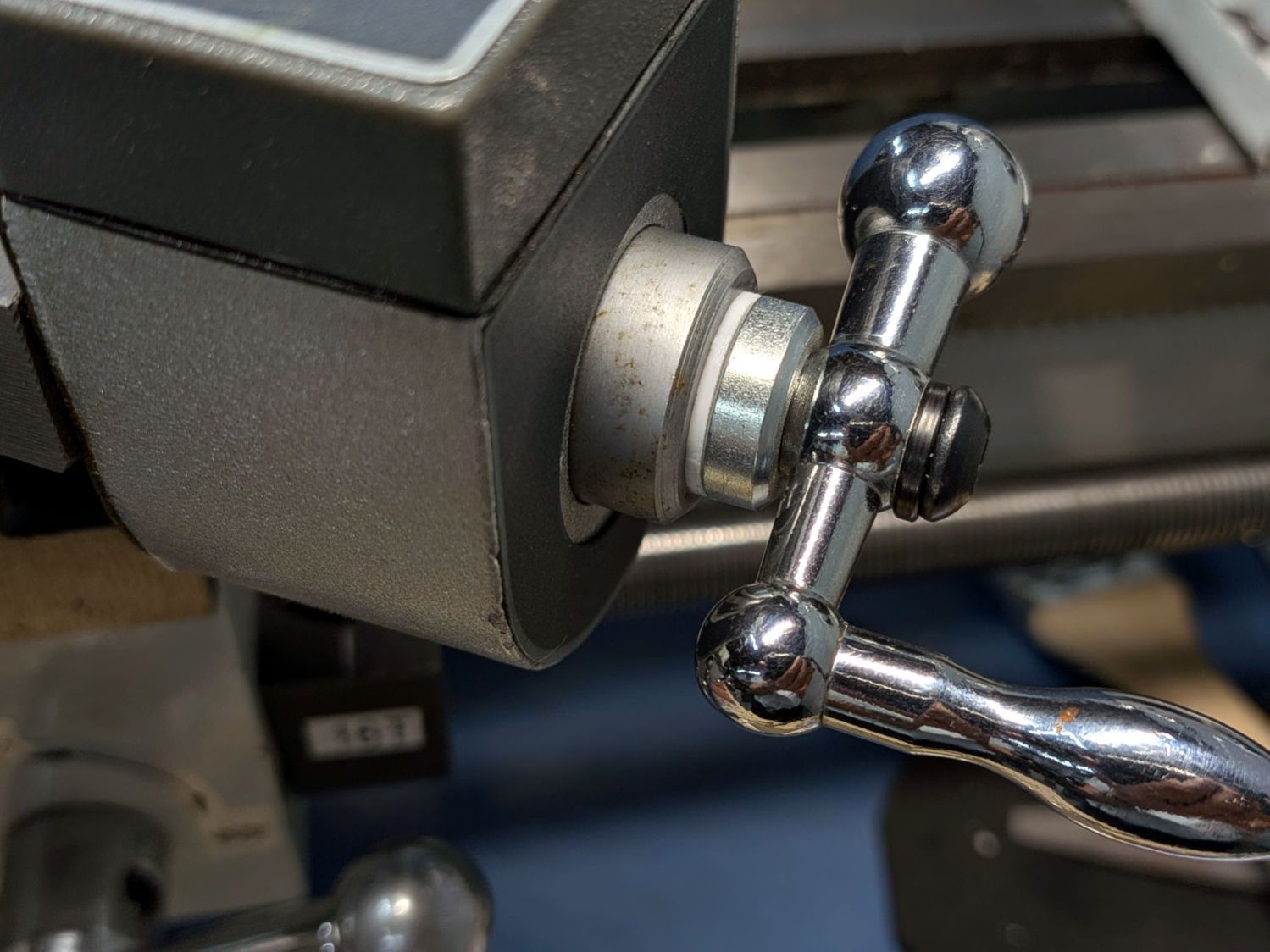
The compound feed screw does not have any backlash adjustment, so fitting a suitable shim between the handle and the DRO spacer is essential:
Mini-lathe – compound handle shim
That one looked nice, but was somewhat too thick.
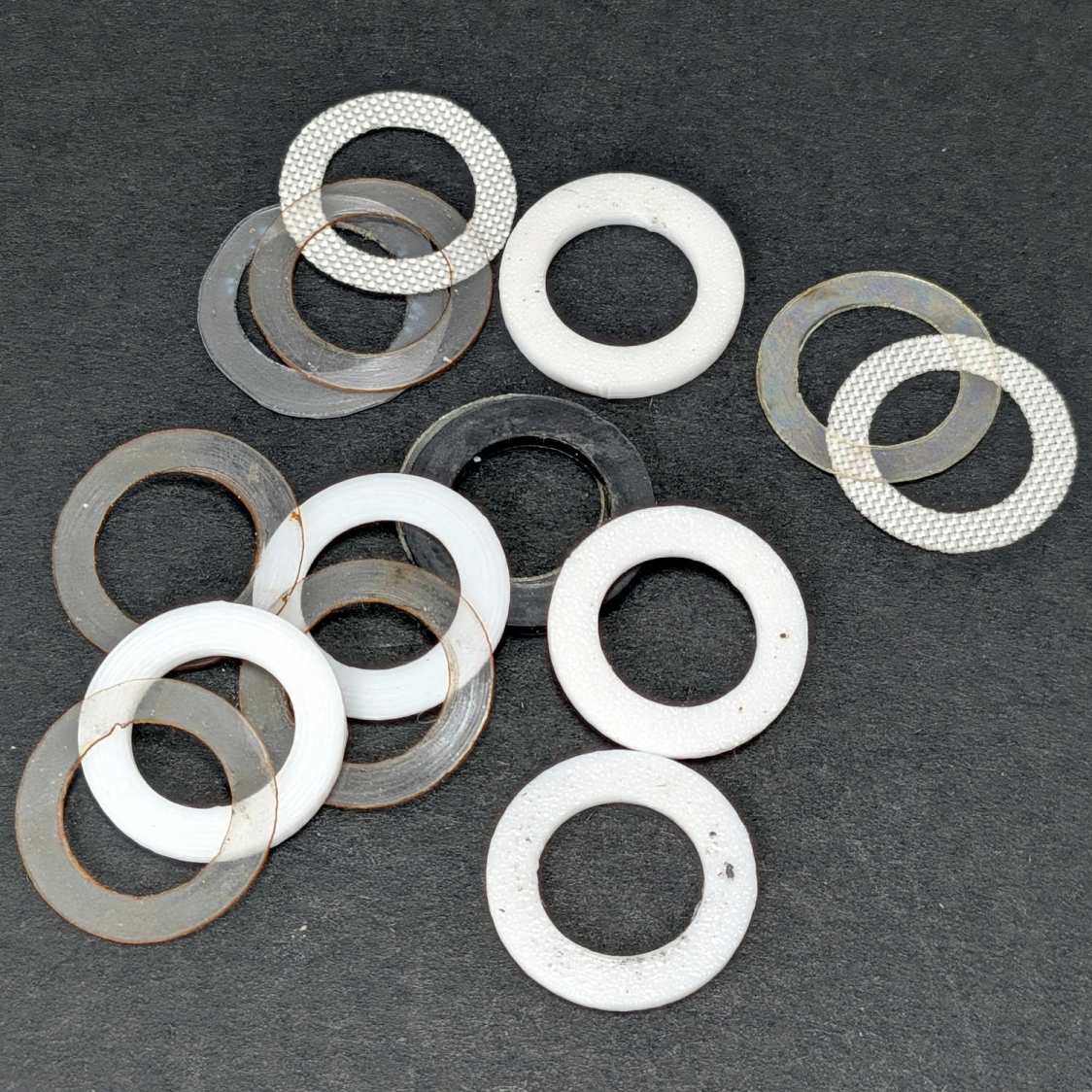
This time around I could laser-cut and 3D print shims (16 mm OD, 10 mm ID) in a variety of thicknesses, some combination of which would surely fill the gap without binding:
Mini-lathe – handle backlash shims
The gnarly clear rings over on the left are the original punched-and-trimmed PETG shims. The fabric-looking ones are PTFE sheets intended for heat-press transfer machines, which Mary has used as a slider sheet to let fabric move easily over her sewing machines. The black one in the middle is 1.5 mm acrylic.
The bright white rings are 3D printed from a few lines of OpenSCAD code:
Washers = [0.5,0.6,0.7,0.8,1.2];

for (i = [0:len(Washers)-1])
  right(i*20.0 - 40.0)
    tube(Washers[i],od=16.0,id=(10.0 + HoleWindage),anchor=BOTTOM);
Print them with 0.1 mm layers in PETG, add a PTFE shim or two, and fiddle about enough to get minimum backlash with reasonable turning force.
The compound feed screw now has 0.16 mm of backlash, which is as good as it’s going to get.
Right now, the only thing preventing the handle from turning on the shaft is the chunky lockwasher gouging both the handle and the cap screw in the end of the shaft, with the side effect of putting far too much pressure on the spacer shims. I want setscrews in the handles bearing on flats filed in the feed screw shafts to put those awful screws + lockwashers out of business, which seems like a good Sherline project.
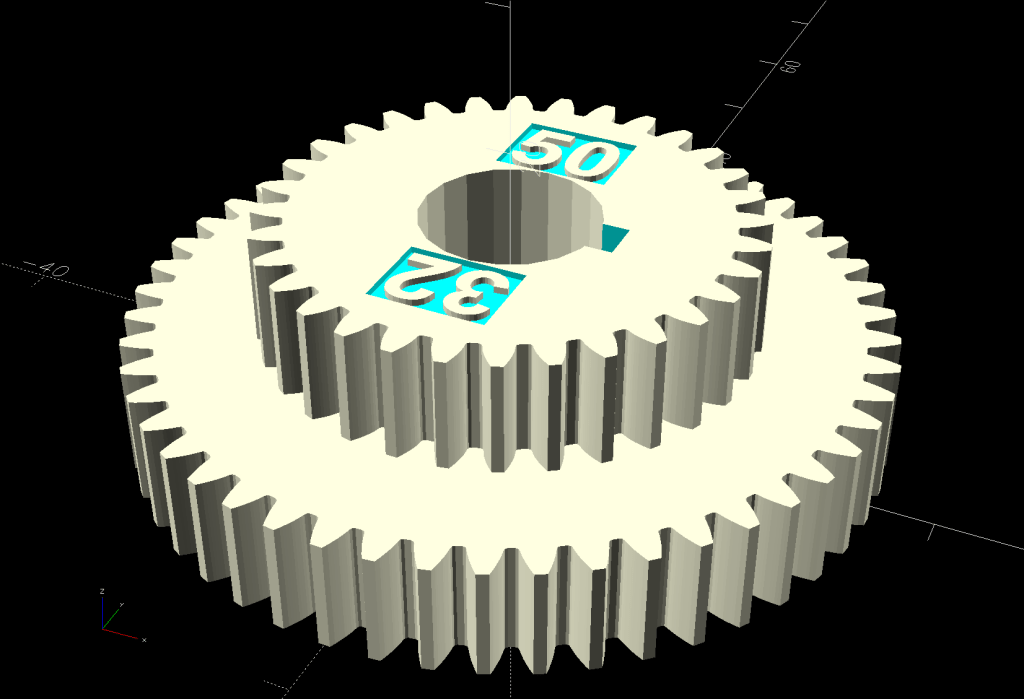
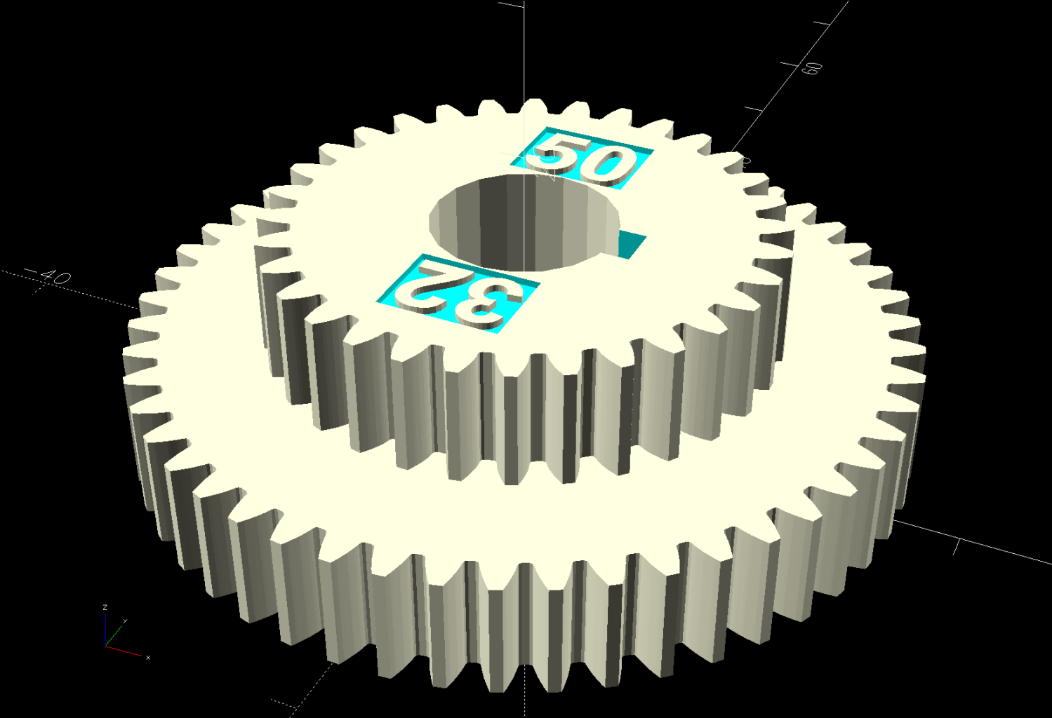
Before turning the PVC conduit to the proper diameter for the Shopvac hose adapter, I set up a 20-50-32-80 change gear train for a 100 TPI finish. While the urethane adhesive cured in the hose, I fed the BC gear pair into my change gear generator:
Mini-lathe stacked change gears – 32-50T – solid model
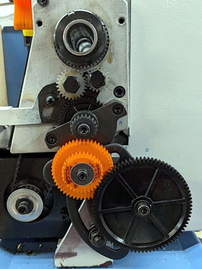
It’s ready for the next time I cut something down to size:
Mini-lathe 100 TPI change gears
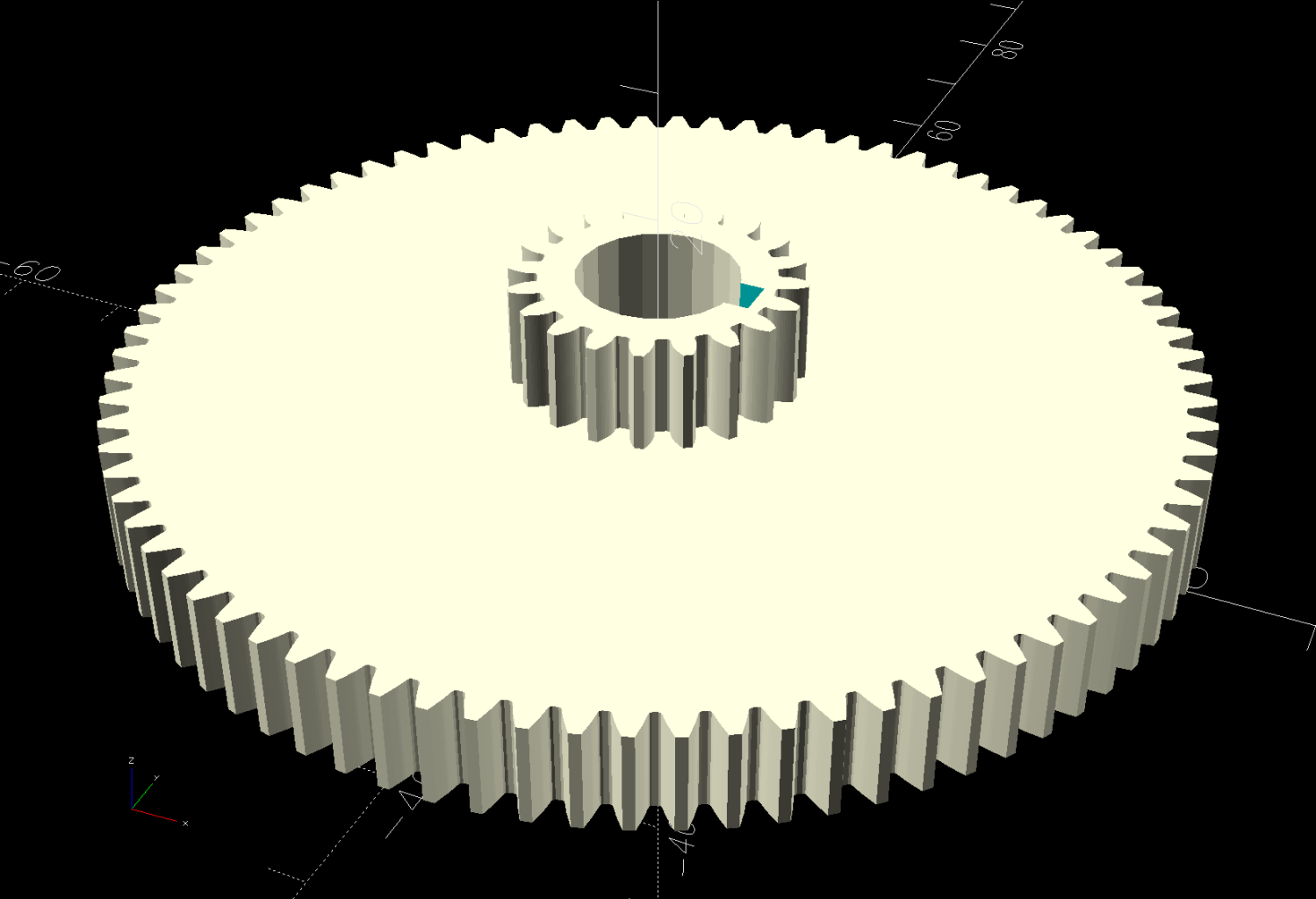
One reference suggests a 256 TPI finish for “general turning”, which works out to 20-80-20-80:
Mini-lathe stacked change gears – 20-80T – solid model
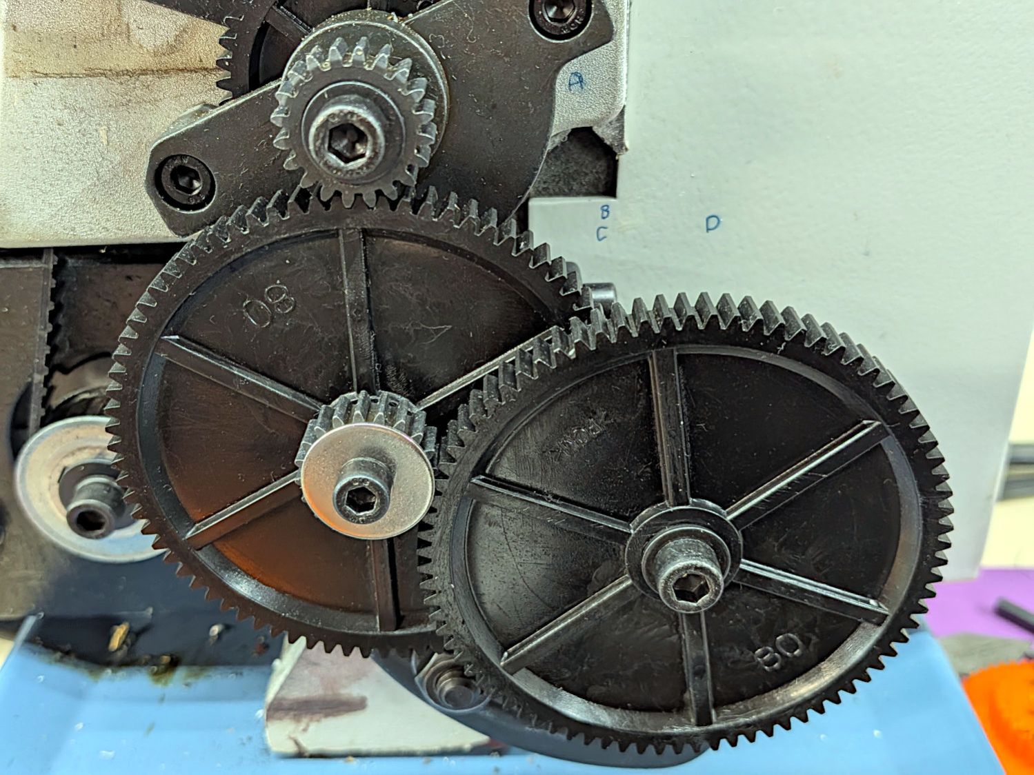
That’s just crazy talk, because the BC washer overlaps the D gear teeth:
Mini-lathe 256 TPI change gears
If all else fails and I really need a 256 TPI finish, lathes are pretty good at making washers.
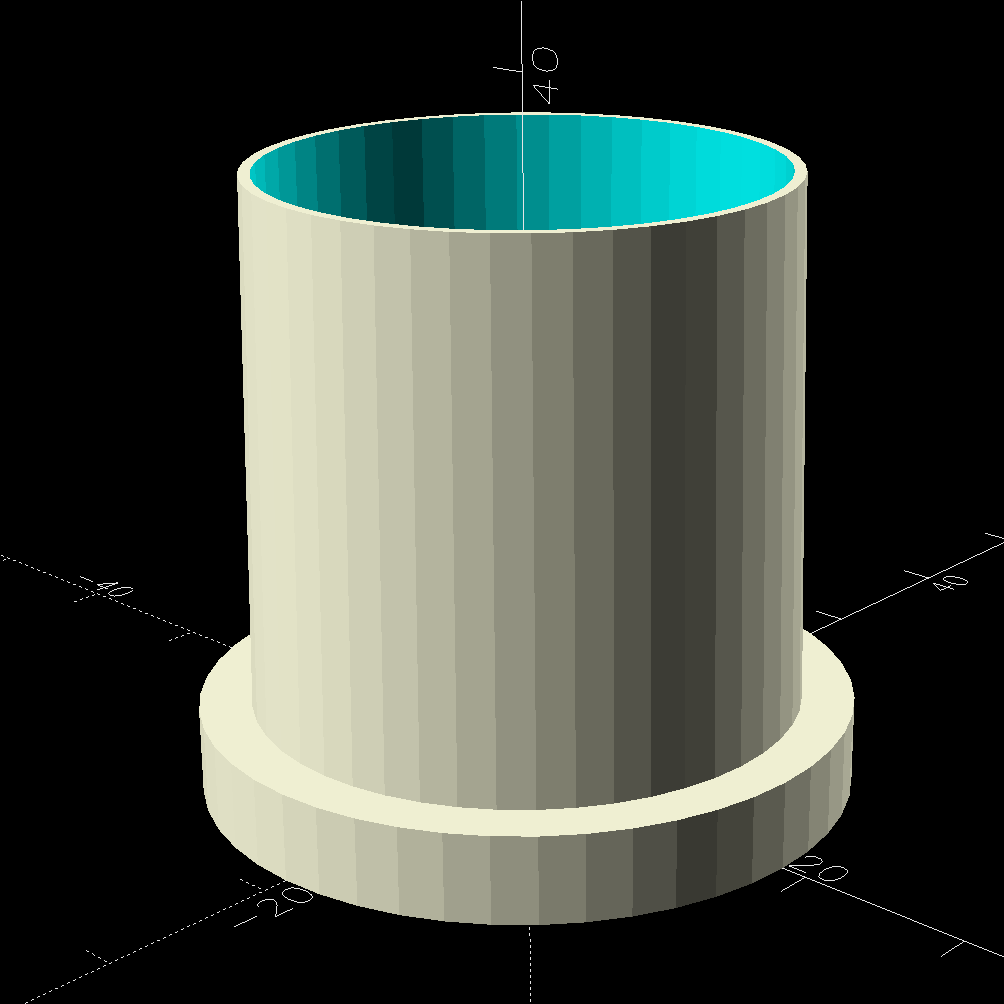
The tapered adapter drags the OpenSCAD code into the BOSL2 era:
Spiral Hose – 1.25in nozzle adapter – solid model
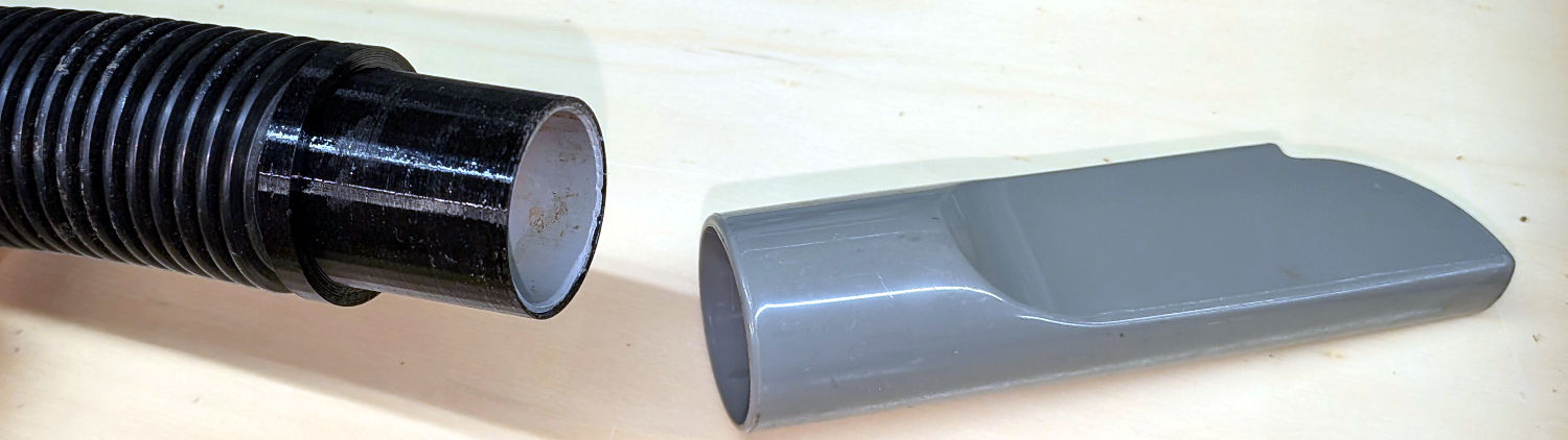
The ID of the hose determined the OD of the lathe-turned PVC tube inside the 3D printed adapter, so a straight pipe would just slide right into both parts.
It would be possible to skip the 3D printing and make the adapter from a single piece of PVC:
Turn one end of the conduit to fit the hose ID
Maneuver the lathe compound to the required 1.05° half-angle
Turn the taper to fit the crevice tool
Clean up the original OD between the two sections
Just turning the whole pipe to a smaller OD and sliding the taper on was definitely easier, particularly given the mini-lathe’s cramped quarters with the compound nearly parallel to the bed.
A generous helping of JB PlasticBonder urethane adhesive bonds the PVC pipe inside the vacuum hose and the tapered adapter.
The as-printed taper perfectly fits the crevice tool shown in the picture and is one wrap of electrical tape smaller than another crevice tool of “the same size”. The Finesse variable handles that situation, should it matter to you.
The OpenSCAD source code:
// Shopvac spiral hose to 1.25 in nozzle
// Ed Nisley - KE4ZNU
// 2026-07-25

include <BOSL2/std.scad>

Finesse = 0.2;             // [-0.5:0.1:0.5]

// PVC pipe liner final OD
PipeOD = 28.5;

/* [Hidden] */

NumSides = 4*3*4;
$fn=NumSides;

Protrusion = 0.1;           // make holes end cleanly
HoleWindage = 0.2;          // make holes large enough to fit

//----------------------
// Dimensions

TAPER_MIN = 0;
TAPER_MAX = 1;
TAPER_LENGTH = 2;

Tool = [30.0,31.1,30.0] + [Finesse,Finesse,0];

FlangeOD = 37.0;
FlangeLength = 5.0;

//render()
difference() {

    union() {
        cyl(FlangeLength,d=FlangeOD,anchor=BOTTOM) position(TOP)
          cyl(Tool[TAPER_LENGTH],d1=Tool[TAPER_MAX],d2=Tool[TAPER_MIN],anchor=BOTTOM);
      }

    down(Protrusion)
      cyl(2*Tool[TAPER_LENGTH] + FlangeLength,d=PipeOD + HoleWindage,anchor=BOTTOM);

}
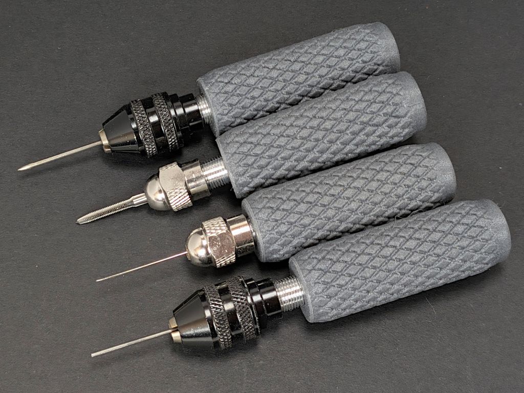
The idea came from the June/July 2026 Machinist’s Workshop, wherein I learned Dremel nuts / chucks fit on a 0.275 inch = 9/32 inch 40 TPI threaded body, drilled through 11/64 inch.
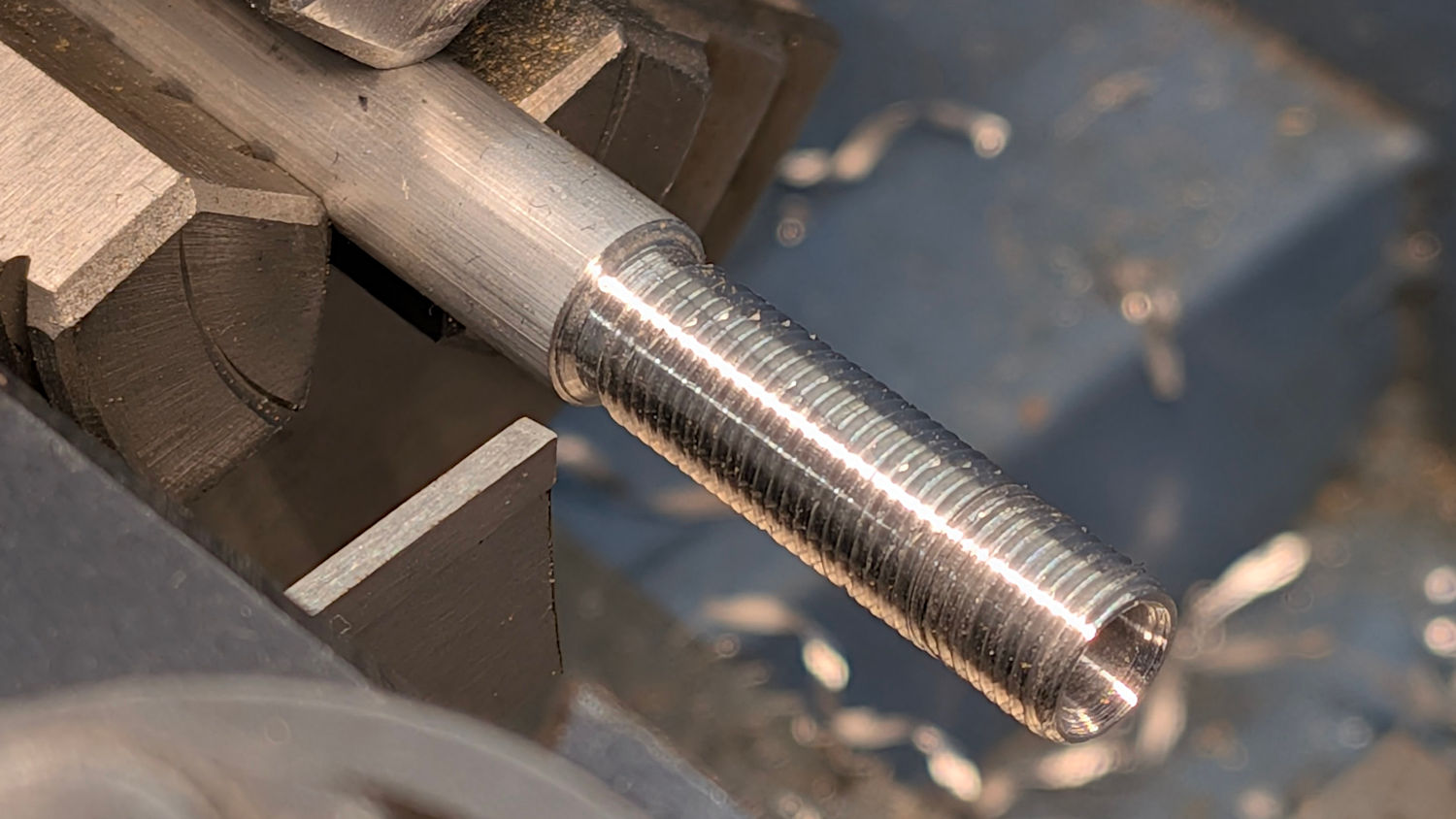
Making such a thing involved some pleasant lathe time:
Dremel Collet Chuck Handle – lathe work
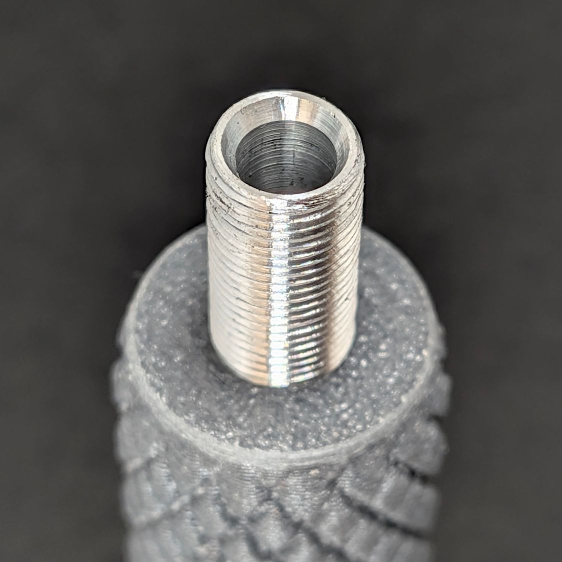
The business end of the body has a slight taper to (ideally) match the collets:
Dremel Collet Chuck Handle – threaded body recess
However, the collets have tapers ranging from 20° to 35°, so I defined a 60° center drill to be Good Enough™ and got a free taper while drilling the central hole.
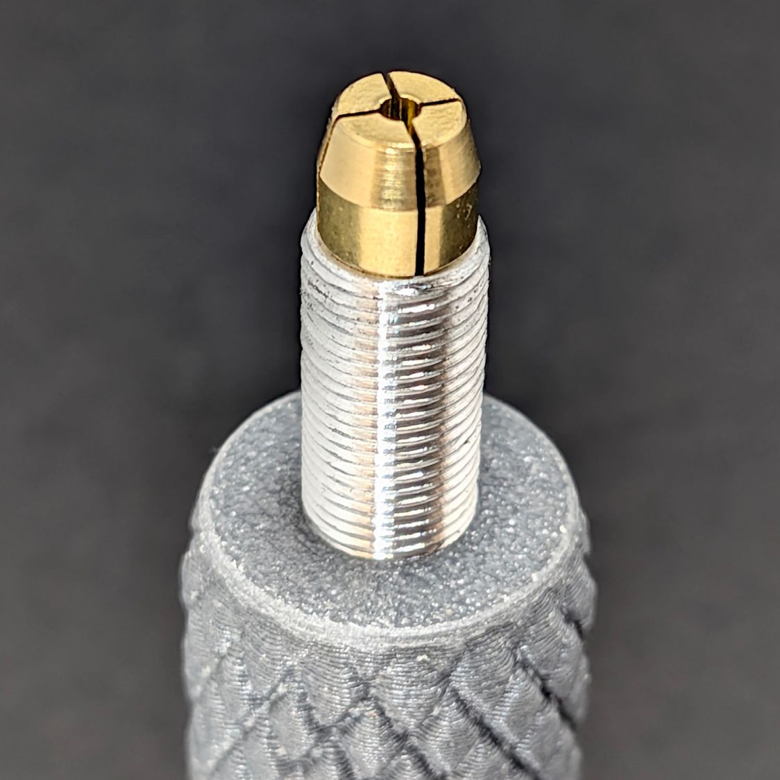
The collets sit in the taper:
Dremel Collet Chuck Handle – collet installed
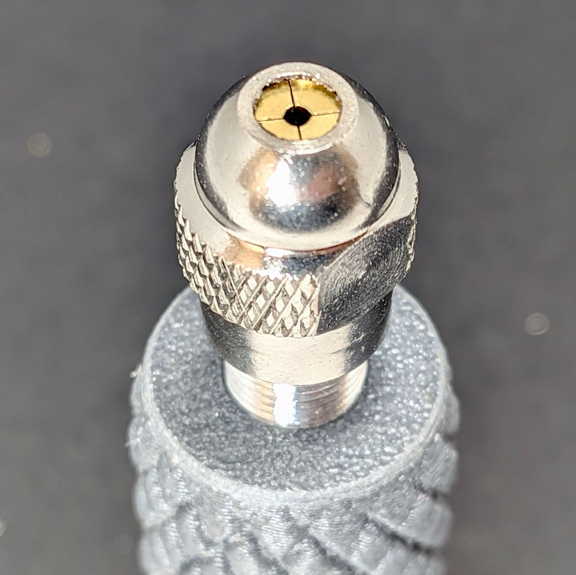
Tightening the nut closes the collet:
Dremel Collet Chuck Handle – threaded body – nut installed
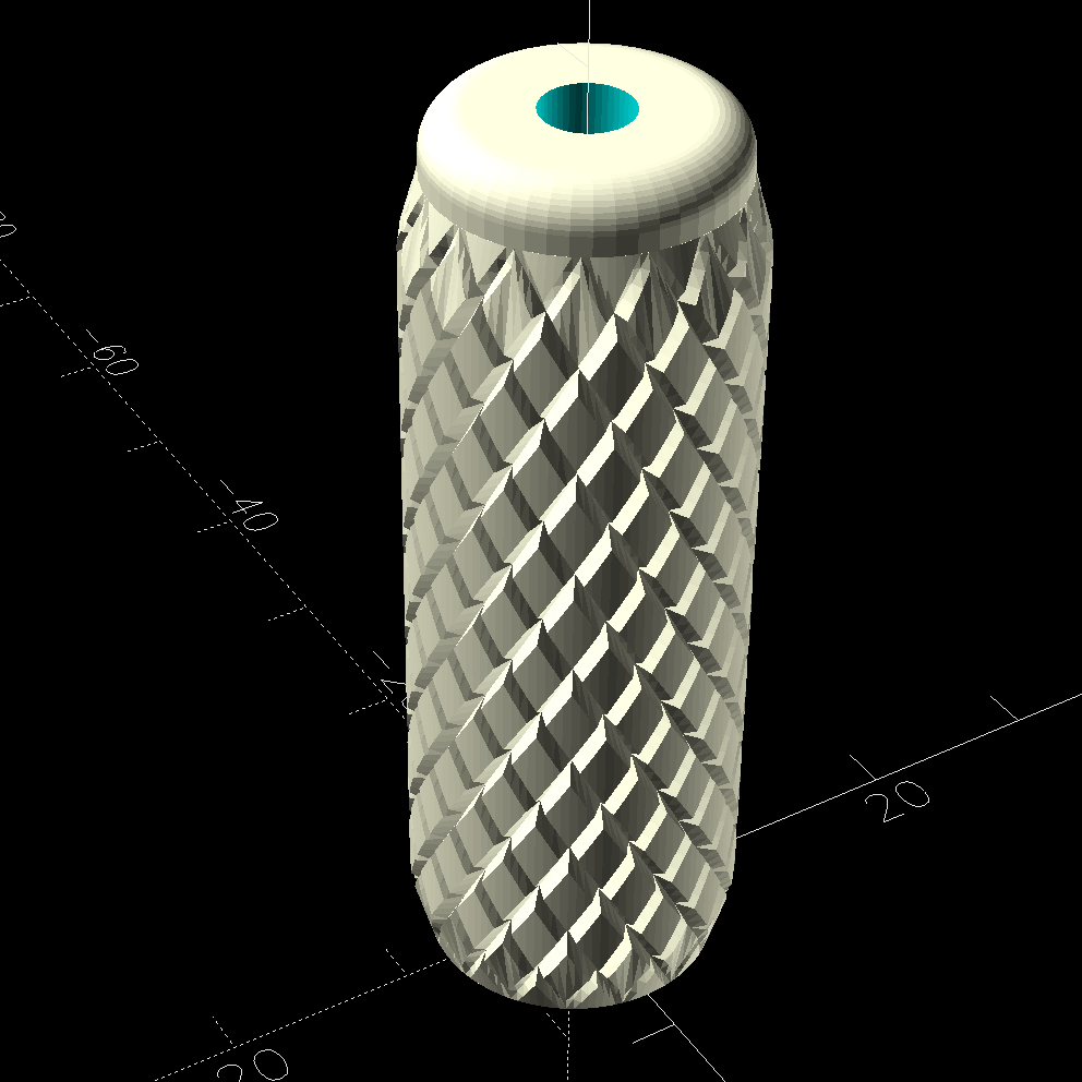
The article described a nicely turned wooden handle, but a somewhat uglier 3D printed handle is fine with me:
Dremel Collet Chuck Handle – solid model – top view
The variables match the threaded body to my fingers:
Protrusion = 0.1;           // make holes end cleanly
HoleWindage = 0.2;          // make holes large enough to fit

ShaftOD = 6.9;       // collet closer thread - 40 TPI 0.275 OD
ShaftID = 4.3;       //  … internal clearance

HandleOD = 15.0;
HandleLength = 45.0;
Knurling = "trunc_diamonds";
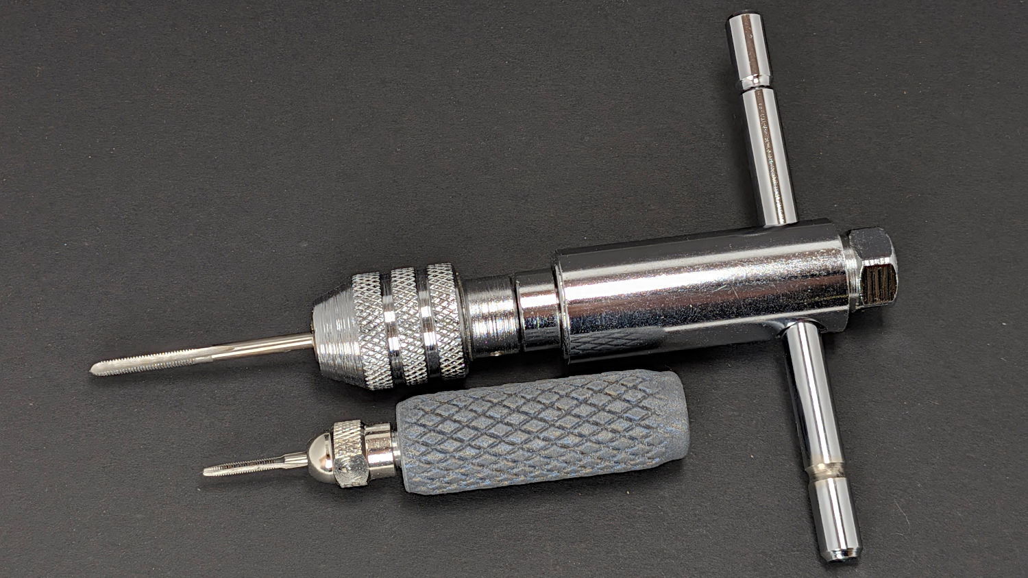
The motivation for all this was to put the smallest taps in a holder suitable for delicate jobs. The smallest chuck on my real tap driver bottoms out on an M3 tap and can’t grip the M2 tap:
Dremel Collet Chuck Handle – M3 vs M2 taps
I try very hard to not tap small holes, but sometimes you gotta do what you gotta do and now I’m better prepared.
Incidentally, the first threaded body I made absolutely did not fit the Dremel nuts. After eliminating everything else, I discovered I’d set up the lathe change gears with a 20-65-45 train, rather than the 20-65-50 train required for 40 TPI with the lathe’s 16 TPI leadscrew.
Protip: Even the best threading job (which I didn’t do on any of those things) can’t make a 36 TPI screw fit into a 40 TPI nut.
That’s not quite “as found”, because it came festooned with the remains of an obviously lab-built Peltier-cooled laser (?) diode fixture:
Rotary positioner – Peltier diode fixture
The positioner sported an obviously aftermarket tapped hole in the side, presumably for mounting to a support:
Rotary positioner – tapped mounting hole
The knob was apparently intended for fine angle adjustment, but it spun freely. Loosening another setscrew on the side released its well-worn parts:
Rotary positioner – drive gear – OEM knob
It’s not clear what the brown ring did, back when it did something, but there were no signs of stripped-off teeth or other debris in the recess; it is a very sloppy fit on the pin holding the knob. The knob may have had a compliant surface engaging the top of the ring, made with a long-since fossilized substance.
It turns out the rotary ring has triangles, not gear teeth:
Rotary positioner – tooth detail
However, setting the gear tooth pressure angle to 45° produces a reasonable triangle:
Rotary positioner – drive gear – solid model – end view
Even so, getting a functional knob required many iterations, primarily because I can’t measure any of the details and had to figure the fit by cut-and-try:
Rotary positioner – drive gear – gallery
The little white dots were an excuse to use the MMU3 for multi-material printing, because why not.
In truth, the knob doesn’t work particularly well, as the forces from the triangular teeth on the rotary ring tend to jam the knob against its pin. The knob might work better with splines driving a squishy TPU tire riding the crests of the rotary ring teeth than a real gear. Perhaps that’s what the original brown ring did before it fossilized.
For now, the positioner returns to the Box o’ Optics Lab Stuff, because it’s the wrong hammer for the Sherline’s laser aligner. It may emerge for a future project, when I’ll have more motivation to build a functional knob.
This file contains hidden or bidirectional Unicode text that may be interpreted or compiled differently than what appears below. To review, open the file in an editor that reveals hidden Unicode characters.
Learn more about bidirectional Unicode characters
The instructions for the Photo Backdrop frame (upon which we hang Mary’s quilts for photos) suggest the crossbar fits on like this:
Photo Backdrop – OEM crossbar installation
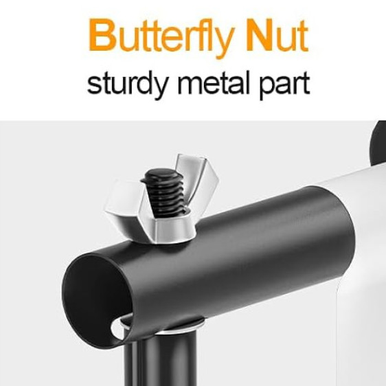
The slot in the bottom is wider than the M10 stud, so the crossbar tends to flop around while assembling it overhead. I immediately replaced the wingnut with a chunky knob for better griptitude, but was never happy with how poorly the whole thing fit together.
This is dramatically better:
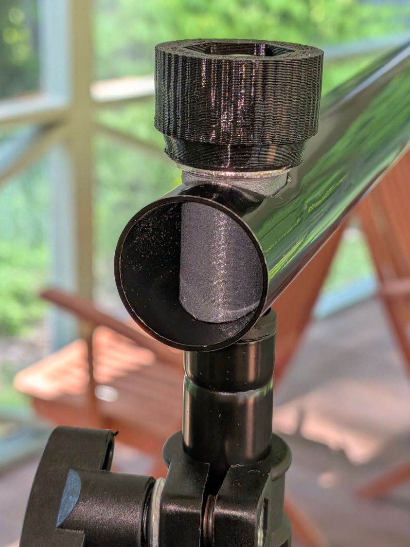
Photo Backdrop – fitting installed
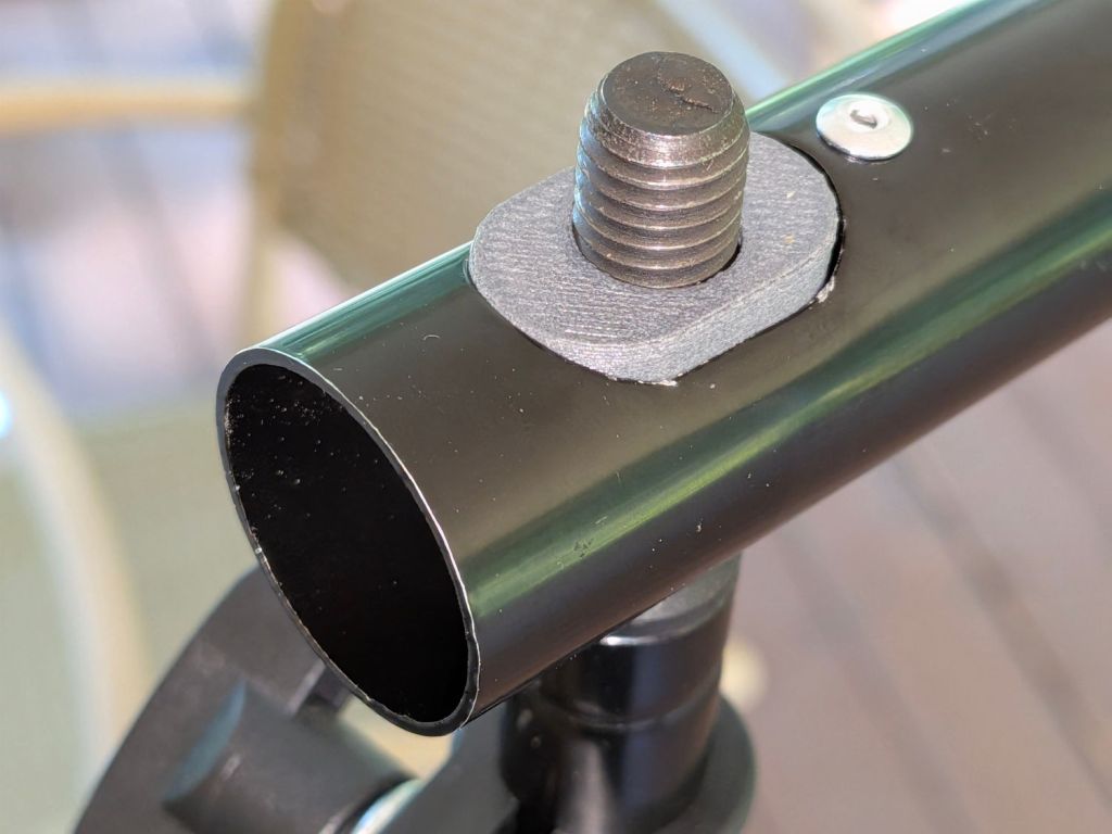
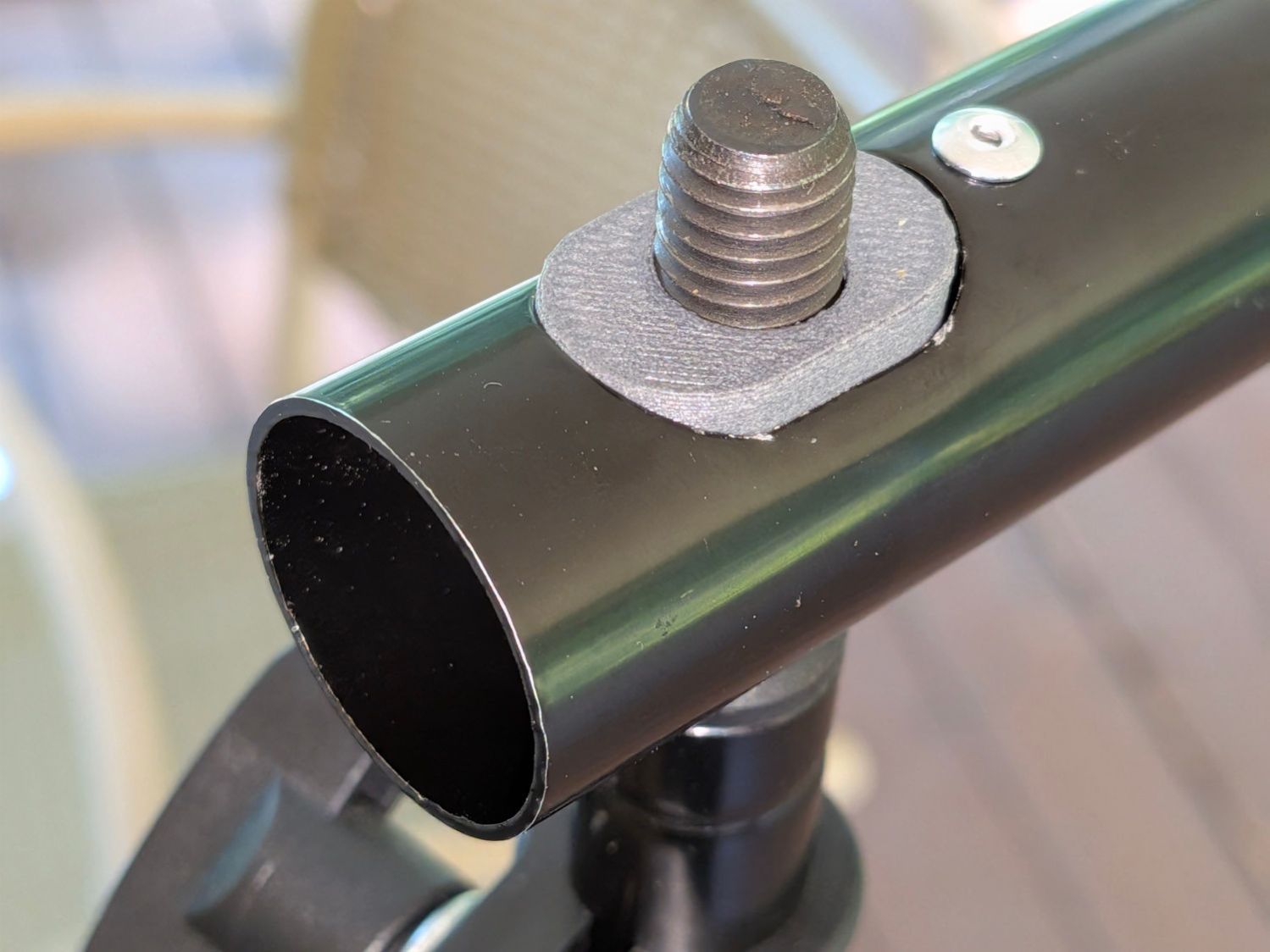
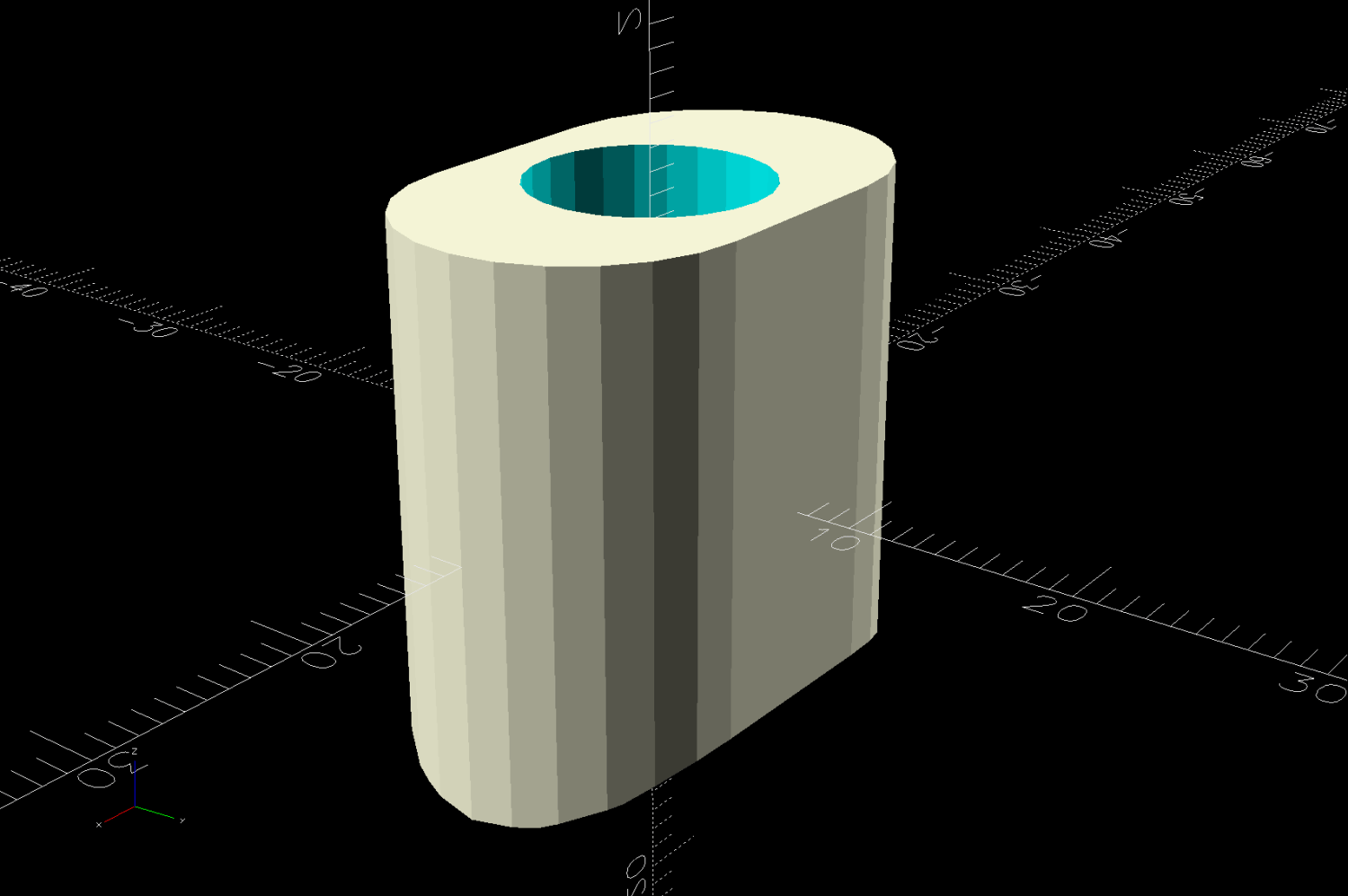
The crossbar is upside-down from the OEM instructions, but the bottom of the gray plug holds the tube firmly to the tripod while the nut seats firmly on the plug’s flat top:
Photo Backdrop – fitting top view
A snippet of 3M 300LSE adhesive sheet holds the plug in place, so that’s one less thing to fiddle with on each end.
This file contains hidden or bidirectional Unicode text that may be interpreted or compiled differently than what appears below. To review, open the file in an editor that reveals hidden Unicode characters.
Learn more about bidirectional Unicode characters