The Smell of Molten Projects in the Morning

Ed Nisley's Blog: Shop notes, electronics, firmware, machinery, 3D printing, laser cuttery, and curiosities. Contents: 100% human thinking, 0% AI slop.

Tag: M2

Using and tweaking a Makergear M2 3D printer

  • TC4Server: Eagle HAL Device

    Dan Newman’s TC4Server turns the TC4 thermocouple board into a USB HID input device that’s compatible with HAL’s hal_input module:

    TC4 on ProtoScrewShield on Leonardo
    TC4 on ProtoScrewShield on Leonardo

    For simplicity (i.e., to avoid writing a special driver), TC4Server misrepresents itself as a nine-axis joystick-like device suited for RC airplane control:

    halrun
    halcmd: loadusr -W hal_input +A Leonardo
    halcmd: show
    ... snippage ...
    Component Pins:
    Owner   Type  Dir         Value  Name
         5  s32   OUT          2941  input.0.abs-rudder-counts
         5  s32   IN           4095  input.0.abs-rudder-flat
         5  s32   IN            255  input.0.abs-rudder-fuzz
         5  bit   OUT          TRUE  input.0.abs-rudder-is-neg
         5  bit   OUT         FALSE  input.0.abs-rudder-is-pos
         5  float IN        32767.5  input.0.abs-rudder-offset
         5  float OUT    -0.9102464  input.0.abs-rudder-position
         5  float IN        32767.5  input.0.abs-rudder-scale
         5  s32   OUT          2947  input.0.abs-rx-counts
         5  s32   IN           4095  input.0.abs-rx-flat
         5  s32   IN            255  input.0.abs-rx-fuzz
         5  bit   OUT          TRUE  input.0.abs-rx-is-neg
         5  bit   OUT         FALSE  input.0.abs-rx-is-pos
         5  float IN        32767.5  input.0.abs-rx-offset
         5  float OUT    -0.9100633  input.0.abs-rx-position
         5  float IN        32767.5  input.0.abs-rx-scale
         5  s32   OUT         65535  input.0.abs-ry-counts
         5  s32   IN           4095  input.0.abs-ry-flat
         5  s32   IN            255  input.0.abs-ry-fuzz
         5  bit   OUT         FALSE  input.0.abs-ry-is-neg
         5  bit   OUT          TRUE  input.0.abs-ry-is-pos
         5  float IN        32767.5  input.0.abs-ry-offset
         5  float OUT             1  input.0.abs-ry-position
         5  float IN        32767.5  input.0.abs-ry-scale
         5  s32   OUT         65535  input.0.abs-rz-counts
         5  s32   IN           4095  input.0.abs-rz-flat
         5  s32   IN            255  input.0.abs-rz-fuzz
         5  bit   OUT         FALSE  input.0.abs-rz-is-neg
         5  bit   OUT          TRUE  input.0.abs-rz-is-pos
         5  float IN        32767.5  input.0.abs-rz-offset
         5  float OUT             1  input.0.abs-rz-position
         5  float IN        32767.5  input.0.abs-rz-scale
         5  s32   OUT         65535  input.0.abs-throttle-counts
         5  s32   IN           4095  input.0.abs-throttle-flat
         5  s32   IN            255  input.0.abs-throttle-fuzz
         5  bit   OUT         FALSE  input.0.abs-throttle-is-neg
         5  bit   OUT          TRUE  input.0.abs-throttle-is-pos
         5  float IN        32767.5  input.0.abs-throttle-offset
         5  float OUT             1  input.0.abs-throttle-position
         5  float IN        32767.5  input.0.abs-throttle-scale
         5  s32   OUT          2957  input.0.abs-wheel-counts
         5  s32   IN           4095  input.0.abs-wheel-flat
         5  s32   IN            255  input.0.abs-wheel-fuzz
         5  bit   OUT          TRUE  input.0.abs-wheel-is-neg
         5  bit   OUT         FALSE  input.0.abs-wheel-is-pos
         5  float IN        32767.5  input.0.abs-wheel-offset
         5  float OUT    -0.9097581  input.0.abs-wheel-position
         5  float IN        32767.5  input.0.abs-wheel-scale
         5  s32   OUT          2942  input.0.abs-x-counts
         5  s32   IN           4095  input.0.abs-x-flat
         5  s32   IN            255  input.0.abs-x-fuzz
         5  bit   OUT          TRUE  input.0.abs-x-is-neg
         5  bit   OUT         FALSE  input.0.abs-x-is-pos
         5  float IN        32767.5  input.0.abs-x-offset
         5  float OUT    -0.9102159  input.0.abs-x-position
         5  float IN        32767.5  input.0.abs-x-scale
         5  s32   OUT          2942  input.0.abs-y-counts
         5  s32   IN           4095  input.0.abs-y-flat
         5  s32   IN            255  input.0.abs-y-fuzz
         5  bit   OUT          TRUE  input.0.abs-y-is-neg
         5  bit   OUT         FALSE  input.0.abs-y-is-pos
         5  float IN        32767.5  input.0.abs-y-offset
         5  float OUT    -0.9102159  input.0.abs-y-position
         5  float IN        32767.5  input.0.abs-y-scale
         5  s32   OUT          2940  input.0.abs-z-counts
         5  s32   IN           4095  input.0.abs-z-flat
         5  s32   IN            255  input.0.abs-z-fuzz
         5  bit   OUT          TRUE  input.0.abs-z-is-neg
         5  bit   OUT         FALSE  input.0.abs-z-is-pos
         5  float IN        32767.5  input.0.abs-z-offset
         5  float OUT     -0.910277  input.0.abs-z-position
         5  float IN        32767.5  input.0.abs-z-scale
         5  s32   OUT          2941  input.1.abs-rudder-counts
         5  s32   IN           4095  input.1.abs-rudder-flat
         5  s32   IN            255  input.1.abs-rudder-fuzz
         5  bit   OUT          TRUE  input.1.abs-rudder-is-neg
         5  bit   OUT         FALSE  input.1.abs-rudder-is-pos
         5  float IN        32767.5  input.1.abs-rudder-offset
         5  float OUT    -0.9102464  input.1.abs-rudder-position
         5  float IN        32767.5  input.1.abs-rudder-scale
         5  s32   OUT          2947  input.1.abs-rx-counts
         5  s32   IN           4095  input.1.abs-rx-flat
         5  s32   IN            255  input.1.abs-rx-fuzz
         5  bit   OUT          TRUE  input.1.abs-rx-is-neg
         5  bit   OUT         FALSE  input.1.abs-rx-is-pos
         5  float IN        32767.5  input.1.abs-rx-offset
         5  float OUT    -0.9100633  input.1.abs-rx-position
         5  float IN        32767.5  input.1.abs-rx-scale
         5  s32   OUT         65535  input.1.abs-ry-counts
         5  s32   IN           4095  input.1.abs-ry-flat
         5  s32   IN            255  input.1.abs-ry-fuzz
         5  bit   OUT         FALSE  input.1.abs-ry-is-neg
         5  bit   OUT          TRUE  input.1.abs-ry-is-pos
         5  float IN        32767.5  input.1.abs-ry-offset
         5  float OUT             1  input.1.abs-ry-position
         5  float IN        32767.5  input.1.abs-ry-scale
         5  s32   OUT         65535  input.1.abs-rz-counts
         5  s32   IN           4095  input.1.abs-rz-flat
         5  s32   IN            255  input.1.abs-rz-fuzz
         5  bit   OUT         FALSE  input.1.abs-rz-is-neg
         5  bit   OUT          TRUE  input.1.abs-rz-is-pos
         5  float IN        32767.5  input.1.abs-rz-offset
         5  float OUT             1  input.1.abs-rz-position
         5  float IN        32767.5  input.1.abs-rz-scale
         5  s32   OUT         65535  input.1.abs-throttle-counts
         5  s32   IN           4095  input.1.abs-throttle-flat
         5  s32   IN            255  input.1.abs-throttle-fuzz
         5  bit   OUT         FALSE  input.1.abs-throttle-is-neg
         5  bit   OUT          TRUE  input.1.abs-throttle-is-pos
         5  float IN        32767.5  input.1.abs-throttle-offset
         5  float OUT             1  input.1.abs-throttle-position
         5  float IN        32767.5  input.1.abs-throttle-scale
         5  s32   OUT          2957  input.1.abs-wheel-counts
         5  s32   IN           4095  input.1.abs-wheel-flat
         5  s32   IN            255  input.1.abs-wheel-fuzz
         5  bit   OUT          TRUE  input.1.abs-wheel-is-neg
         5  bit   OUT         FALSE  input.1.abs-wheel-is-pos
         5  float IN        32767.5  input.1.abs-wheel-offset
         5  float OUT    -0.9097581  input.1.abs-wheel-position
         5  float IN        32767.5  input.1.abs-wheel-scale
         5  s32   OUT          2942  input.1.abs-x-counts
         5  s32   IN           4095  input.1.abs-x-flat
         5  s32   IN            255  input.1.abs-x-fuzz
         5  bit   OUT          TRUE  input.1.abs-x-is-neg
         5  bit   OUT         FALSE  input.1.abs-x-is-pos
         5  float IN        32767.5  input.1.abs-x-offset
         5  float OUT    -0.9102159  input.1.abs-x-position
         5  float IN        32767.5  input.1.abs-x-scale
         5  s32   OUT          2942  input.1.abs-y-counts
         5  s32   IN           4095  input.1.abs-y-flat
         5  s32   IN            255  input.1.abs-y-fuzz
         5  bit   OUT          TRUE  input.1.abs-y-is-neg
         5  bit   OUT         FALSE  input.1.abs-y-is-pos
         5  float IN        32767.5  input.1.abs-y-offset
         5  float OUT    -0.9102159  input.1.abs-y-position
         5  float IN        32767.5  input.1.abs-y-scale
         5  s32   OUT          2940  input.1.abs-z-counts
         5  s32   IN           4095  input.1.abs-z-flat
         5  s32   IN            255  input.1.abs-z-fuzz
         5  bit   OUT          TRUE  input.1.abs-z-is-neg
         5  bit   OUT         FALSE  input.1.abs-z-is-pos
         5  float IN        32767.5  input.1.abs-z-offset
         5  float OUT     -0.910277  input.1.abs-z-position
         5  float IN        32767.5  input.1.abs-z-scale
    
    ... snippage ...
    Parameters:
    Owner   Type  Dir         Value  Name
         5  s32   RO          65535  input.0.abs-rudder-max
         5  s32   RO              0  input.0.abs-rudder-min
         5  s32   RO          65535  input.0.abs-rx-max
         5  s32   RO              0  input.0.abs-rx-min
         5  s32   RO          65535  input.0.abs-ry-max
         5  s32   RO              0  input.0.abs-ry-min
         5  s32   RO          65535  input.0.abs-rz-max
         5  s32   RO              0  input.0.abs-rz-min
         5  s32   RO          65535  input.0.abs-throttle-max
         5  s32   RO              0  input.0.abs-throttle-min
         5  s32   RO          65535  input.0.abs-wheel-max
         5  s32   RO              0  input.0.abs-wheel-min
         5  s32   RO          65535  input.0.abs-x-max
         5  s32   RO              0  input.0.abs-x-min
         5  s32   RO          65535  input.0.abs-y-max
         5  s32   RO              0  input.0.abs-y-min
         5  s32   RO          65535  input.0.abs-z-max
         5  s32   RO              0  input.0.abs-z-min
         5  s32   RO          65535  input.1.abs-rudder-max
         5  s32   RO              0  input.1.abs-rudder-min
         5  s32   RO          65535  input.1.abs-rx-max
         5  s32   RO              0  input.1.abs-rx-min
         5  s32   RO          65535  input.1.abs-ry-max
         5  s32   RO              0  input.1.abs-ry-min
         5  s32   RO          65535  input.1.abs-rz-max
         5  s32   RO              0  input.1.abs-rz-min
         5  s32   RO          65535  input.1.abs-throttle-max
         5  s32   RO              0  input.1.abs-throttle-min
         5  s32   RO          65535  input.1.abs-wheel-max
         5  s32   RO              0  input.1.abs-wheel-min
         5  s32   RO          65535  input.1.abs-x-max
         5  s32   RO              0  input.1.abs-x-min
         5  s32   RO          65535  input.1.abs-y-max
         5  s32   RO              0  input.1.abs-y-min
         5  s32   RO          65535  input.1.abs-z-max
         5  s32   RO              0  input.1.abs-z-min
    ... snippage ...
    

    Dan’s program assigns the outputs thusly:

    • Wheel – ambient temperature as measured on TC4 board
    • X Y Z Rudder – thermocouples – channels 1 through 4
    • RX RY RZ  Throttle – thermistors – channels 5 through 8

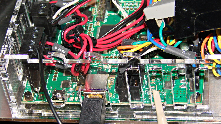
    I created a huge Eagle device that encapsulates the whole thing. A simple demo schematic includes the constants that make the temperatures come out in °C:

    TC4Server - Eagle Schematic
    TC4Server – Eagle Schematic

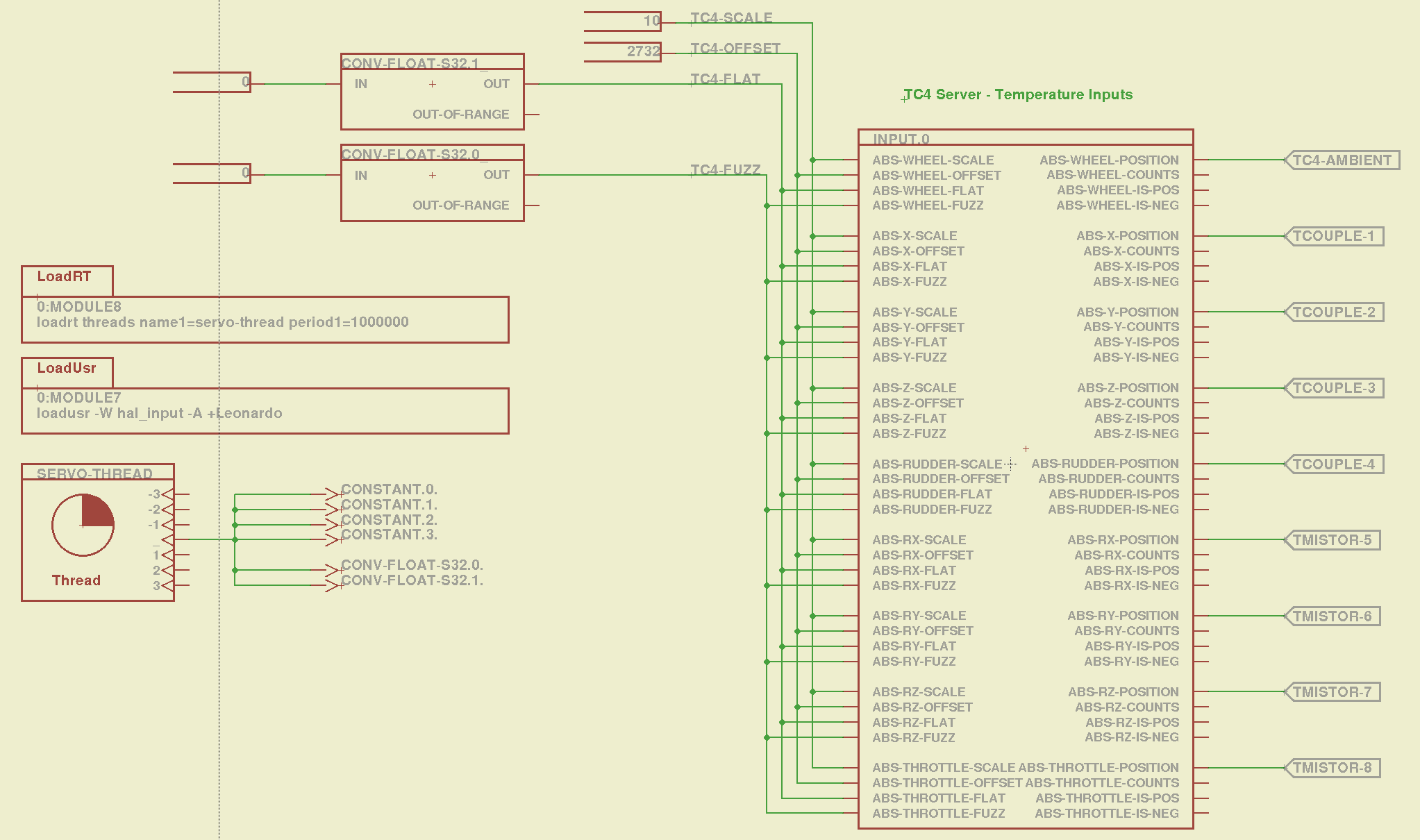
    That picture produces this HAL file:

    # HAL config file automatically generated by Eagle-CAD ULP:
    # [/mnt/bulkdata/Project Files/eagle/ulp/hal-write-2.5.ulp]
    # (C) Martin Schoeneck.de 2008
    # Charalampos Alexopoulos 2011
    # Mods Ed Nisley KE4ZNU 2010 2013
    # Path        [/mnt/bulkdata/Project Files/eagle/projects/LinuxCNC for M2/]
    # ProjectName [LinuxCNC M2 - TC4Server Test]
    # File name   [/mnt/bulkdata/Project Files/eagle/projects/LinuxCNC for M2/TC4Server.hal]
    # Created     [20:03:16 03-Jun-2013]
    
    ####################################################
    # Load realtime and userspace modules
    loadusr -W hal_input -A +Leonardo
    loadrt threads name1=servo-thread period1=1000000
    loadrt constant        count=4
    loadrt conv_float_s32        count=2
    
    ####################################################
    # Hook functions into threads
    addf constant.0        servo-thread
    addf constant.1        servo-thread
    addf constant.2        servo-thread
    addf constant.3        servo-thread
    addf conv-float-s32.0        servo-thread
    addf conv-float-s32.1        servo-thread
    
    ####################################################
    # Set parameters
    
    ####################################################
    # Set constants
    setp constant.0.value    10
    setp constant.1.value    2732
    setp constant.2.value    0
    setp constant.3.value    0
    
    ####################################################
    # Connect Modules with nets
    net n_2 constant.2.out conv-float-s32.1.in
    net n_3 constant.3.out conv-float-s32.0.in
    net tc4-ambient input.0.abs-wheel-position
    net tc4-flat input.0.abs-wheel-flat input.0.abs-x-flat input.0.abs-y-flat input.0.abs-z-flat input.0.abs-rudder-flat input.0.abs-rx-flat input.0.abs-ry-flat input.0.abs-rz-flat input.0.abs-throttle-flat conv-float-s32.1.out
    net tc4-fuzz input.0.abs-throttle-fuzz input.0.abs-rz-fuzz input.0.abs-ry-fuzz input.0.abs-rx-fuzz input.0.abs-rudder-fuzz input.0.abs-z-fuzz input.0.abs-y-fuzz input.0.abs-x-fuzz input.0.abs-wheel-fuzz conv-float-s32.0.out
    net tc4-offset input.0.abs-wheel-offset input.0.abs-x-offset input.0.abs-y-offset input.0.abs-z-offset input.0.abs-rudder-offset input.0.abs-rx-offset input.0.abs-ry-offset input.0.abs-rz-offset input.0.abs-throttle-offset constant.1.out
    net tc4-scale input.0.abs-wheel-scale input.0.abs-x-scale input.0.abs-y-scale input.0.abs-z-scale input.0.abs-rudder-scale input.0.abs-rx-scale input.0.abs-ry-scale input.0.abs-rz-scale input.0.abs-throttle-scale constant.0.out
    net tcouple-1 input.0.abs-x-position
    net tcouple-2 input.0.abs-y-position
    net tcouple-3 input.0.abs-z-position
    net tcouple-4 input.0.abs-rudder-position
    net tmistor-5 input.0.abs-rx-position
    net tmistor-6 input.0.abs-ry-position
    net tmistor-7 input.0.abs-rz-position
    net tmistor-8 input.0.abs-throttle-position
    

    Fire it up with halrun to see the temperatures (alphabetically by the pin name):

    halrun -I -f TC4Server.hal
    halcmd: start
    halcmd: show pin *position
    Component Pins:
    Owner   Type  Dir         Value  Name
         5  float OUT          20.9  input.0.abs-rudder-position ==> tcouple-4
         5  float OUT          21.5  input.0.abs-rx-position ==> tmistor-5
         5  float OUT        6280.3  input.0.abs-ry-position ==> tmistor-6
         5  float OUT        6280.3  input.0.abs-rz-position ==> tmistor-7
         5  float OUT        6280.3  input.0.abs-throttle-position ==> tmistor-8
         5  float OUT          22.5  input.0.abs-wheel-position ==> tc4-ambient
         5  float OUT            21  input.0.abs-x-position ==> tcouple-1
         5  float OUT            21  input.0.abs-y-position ==> tcouple-2
         5  float OUT          20.8  input.0.abs-z-position ==> tcouple-3
    

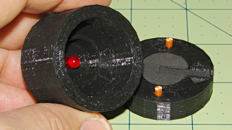
    The sensors do not correspond to the picture at the top: only the first thermocouple and first thermistor are connected ; the ADC returns bogus data for disconnected inputs, which means you must be careful about tightening the wires and checking the result. Dan’s firmware has the ability to disable unused sensors, in which case you get a huge value; when used for heater control, a sensor failing high means the heater will turn off, but, should you use this gadget in a freezer, you might want them to fail low (so modify the code for your own use).

    The ambient temperature reported for the board runs 1 or 2 °C higher than the actual ambient air temperature, probably because of all those components doing useful things up close to the sensor chip. That particular ambient temperature serves as the cold junction reference for the thermocouples; the other temperatures don’t change very much as the board warms up, so it’s all good.

    Remember to issue the start command in halrun, because otherwise nothing changes.

    Also remember that you must configure TC4Server with the thermistor characteristics before you use it as a hal_input device.

  • UDEV Rules for M2’s HAL Devices

    Rather than have a bunch of separate rule files for each USB HID device I’ll be using with LinuxCNC on the M2, here they are in one lump:

    cat /etc/udev/rules.d/hal-input.rules
    # Rules to configure input device permissions for hal_input
    
    ATTRS{product}=="Nostromo SpeedPad2",GROUP="plugdev",MODE="0660"
    ATTRS{product}=="Arduino Leonardo",GROUP="plugdev",MODE="0660"
    ATTRS{product}=="Logitech Dual Action",GROUP="plugdev",MODE="0660"
    

    The strings are case-sensitive and must match exactly. That post (among others) describes the whole dance required to get all the information.

    Remember to add yourself to the plugdev group, too.

  • Marlin Firmware: Stepper Interrupt Timing

    Based on the discussion attached to the post on Z axis numbers, I wanted to take a look at the points where Marlin switches from one step per interrupt to two, then to four, just to see what the timing looks like. The RAMBo board has neatly labeled test points, to which I tack-soldered a pin for the scope probe poked through one of the ventilation slots, and an unused power connector on the left edge of the PCB that provided a ground point (admittedly, much too far away for good RF grounding, but it suffices for CMOS logic signals). The Tek Hall-effect current probe leaning in from the top right captures the current in one of the X axis windings:

    X axis Step and Current probes
    X axis Step and Current probes

    I’ve reset the Marlin constants based on first principles, per the notes on distance, speed, and acceleration, so they’re not representative of the as-shipped M2 firmware. Recapping the XY settings:

    • Distance: 88.89 step/mm
    • Speed: 450 mm/s = 27000 mm/min
    • Acceleration: 5000 mm/s2, with the overall limit at 10 m/s2

    The maximum interrupt frequency is about 10 kHz and the handler can issue zero, one, two, or four steps per axis per interrupt as required by the speed along each axis, up to a maximum of step rate of 40 kHz. There are complexities involved which I do not profess to understand.

    The maximum 10 kHz step rate for one-step-per-interrupt motion corresponds to a speed of:

    112.5 mm/s = (10000 step/s) / (88.89 step/mm)

    The maximum 40 kHz step rate produces, naturally enough, four times that speed:

    450 mm/s = (40000 step/s) / (88.89 step/mm)

    Assuming constant acceleration, the distance required to reach a given speed from a standing start or to decelerate from that speed to a complete stop is:
    x = v2 / (2 * a)

    The time required to reach that speed is:
    t = v/a

    Accelerating at 5000 mm/s2:

    • 112.5 mm/s = 6700 mm/min → 1.27 mm, 22.5 ms
    • 150 mm/s = 9000 mm/min → 2.25 mm, 30 ms
    • 450 mm/s = 27000 mm/min → 20.3 mm and 90 ms

    An overview of a complete 6 mm move at 150 mm/s shows the acceleration and deceleration at each end, with a constant-speed section in the middle:

    X Axis 150 mm-s 6 mm - overview
    X Axis 150 mm-s 6 mm – overview

    The bizarre patterns in the traces come from hp2xx‘s desperate attempts to discern the meaning of the scope’s HPGL graphic data where the trace forms a solid block of color; take it as given that there’s no information in the pattern. I described the trace conversion process there.

    The upper trace shows the X axis motor winding current at a scale of 500 mA/div, with far more hash than one would expect. The RAMBo drivers evidently produce much more current noise than the brick drivers I intend to use.

    The lower trace is the X axis step signal produced by the Arduino microcontroller. You can barely make out the individual step signals at each end, but there’s not enough horizontal resolution to show them when the motor moves at a reasonable pace.

    In round numbers, the acceleration and deceleration should require about 30 ms each. The overall move takes 63 ms, so the constant-speed section in the middle must be about 3 ms long. That’s probably not right…

    Here’s a closer look at the step pulses as the motion starts from zero on the way to 150 mm/s:

    X Axis 150 mm-s 6 mm - 1 ms-div 0 ms dly
    X Axis 150 mm-s 6 mm – 1 ms-div 0 ms dly

    Over on the right, the 5 kHz step rate after 8.5 ms suggests a speed of 56 mm/s and counting 28 pulses says it moved 0.32 mm. Plugging those numbers into the equations:

    • a = v/t = 6600 mm/s2
    • a = (2 * x)/t2 = 8900 mm/s2

    It’s not clear (to me, anyway) whether:

    • The firmware accelerates faster than the alleged 5000 mm/s2 limit
    • It’s accelerating near the overall limit of 10000 mm/s2
    • The acceleration isn’t constant: starts high, then declines
    • The measurement accuracy doesn’t support any conclusions
    • I understand what’s happening

    In order to see the double- and quad-step outputs, here’s a 50 mm move at 450 mm/s, with a 19 ms delay to the point where the interrupt handler transitions from single-step to double-step output:

    X Axis 450 mm-s 50 mm - 200 us-div 19 ms dly
    X Axis 450 mm-s 50 mm – 200 us-div 19 ms dly

    The interrupt frequency drops from just under 10 kHz to a bit under 5 kHz, with the doubled pulses about 16 μs apart. At the transition, the axis speed is 112.5 mm/s, pretty much as predicted.

    If that’s the case, the overall acceleration to the transition works out to:

    5800 mm/s2 = (113 mm/s) / (19.5 ms)

    Delaying the traces to 41.9 ms after the motion starts shows the double-to-quad step transition:

    X Axis 450 mm-s 50 mm - 100 us-div 41.9 ms dly
    X Axis 450 mm-s 50 mm – 100 us-div 41.9 ms dly

    Once again, the pulse frequency drops from 10 kHz down to 5 kHz. The speed is now 225 mm/s, half the maximum possible speed, which also makes sense: at top speed, the pulses will be essentially continuous at 40 kHz.

    The average acceleration from the start of the motion:

    5300 mm/s2 = (225 mm/s) / (42.1 ms)

    That implies the initial acceleration starts higher than the limit, but it evens out on the way to the commanded speed.

    Those scope shots come from moving only the X axis. Moving both the X and Y axes, with Trace 1 now showing the Y axis output, for 50 mm at 450 mm/s, produces similar results; the Y axis output lags the X axis by a few microseconds:

    XY 450 mm-s 50 mm - 100 us-div 19.5 ms dly
    XY 450 mm-s 50 mm – 100 us-div 19.5 ms dly

    Once again, that’s at the single- to double-step transition at 19+ ms. The overall timing doesn’t depend on how many axes are moving, as long as they can accelerate at the same pace; otherwise, the firmware must adjust the accelerations to make both axes track the intended path.

    None of this is too surprising.

    For a motor running at a constant speed just beyond the single-to-double step transition at 112.5 mm/s or the double-to-quad transition at 225 mm/s, the rotor motion should have a 5 kHz perturbation around its nominal position: it coasts for nearly the entire period, then a pair of steps kicks it toward the proper position. At those transitions, the rotor turns at:

    3.2 rev/s = (10000 step/s) / (3200 step/rev)
    6.4 rev/s = (20000 step/s) / (3200 step/rev)

    The perturbation should look like a 5 kHz oscillation (not exactly sinusoidal, maybe triangular?) superimposed on the nominal position, which is changing more-or-less parabolically as a function of time. I expect that the overall inertia damps it out pretty well, but I’d like to attach a rotary encoder to the motor shaft (or a linear encoder to the axis) to show the actual outcome, but I don’t have the machinery for that.

    In any event, LinuxCNC’s step outputs should behave better, which is why I’m doing this whole thing in the first place…

  • Makergear M2: Platform Stabilization

    The M2’s build platform consists of an 8×10 inch glass slab atop an aluminum spider, all supported by a trio of fairly stiff springs. Back when I was experimenting with excessive acceleration, I inserted some silicone rubber cylinders to boost the spring constant and stabilize the platform

    The same vibration isolators that provided the vacuum cleaner’s floor brush rollers came through again:

    Silicone rubber pads for M2 platform - punching
    Silicone rubber pads for M2 platform – punching

    I removed the screws and springs one by one, tucked a cylinder inside the spring, and reinstalled it:

    Silicone rubber pads for M2 platform - installed
    Silicone rubber pads for M2 platform – installed

    The trick is to park the nozzle near the edge of the platform where it will rise without the screw holding it down, measure the distance twixt nozzle and platform, lower the platform by a (known!) 50 mm, install the cylinder, raise the platform, then tweak the screw to put the same distance between the nozzle and the platform as you started with.

    This probably doesn’t make much difference with the default 3 m/s2 acceleration, but up around 10 m/s2 it seemed wobbly. No suprise: that’s over 1 G of lateral acceleration and the platform weighs a pound or so.

  • Hexagonal Chain Mail

    Everybody at the Squidwrench Show-n-Tell loved the chain mail. I printed up a sheet of Ablapo’s hexagonal chain mail before the show (because it takes forever) and it came out very nicely on the M2’s larger platform:

    Hexagonal Chain Mail - on platform
    Hexagonal Chain Mail – on platform

    The first layers sprinkle a bazillion little shapes all over the platform:

    Hexagonal Chain Mail - first layer
    Hexagonal Chain Mail – first layer

    It makes a nice doily for my desk lamp:

    Hexagonal Chain Mail - lamp doily
    Hexagonal Chain Mail – lamp doily

    The odd blue coloration must be an optical effect, because it’s not visible on the black PLA.

  • 3D Printing Show-n-Tell

    So the local hackerspace put on a show in Highland and, being the guy with the 3D printer, I volunteered for a few hours of stand-up comedy.

    A pile of stuff provided talking points:

    3D Printing This Way - with clutter
    3D Printing This Way – with clutter

    Four pages of solid model images on nice glossy photo paper let me talk about what must happen before the plastic emerges:

    I loves me some OpenSCAD modeling, yes, I do…

    Signage festooned with sample critters dragged ’em in off the street:

    3D Printing This Way - signs on post
    3D Printing This Way – signs on post

    The printer produced a steady stream of tiny owls:

    M2 - Mini owl on platform
    M2 – Mini owl on platform

    And the ever-popular whistle:

    M2 - Whistle on platform
    M2 – Whistle on platform

    A good time was had by all!

  • LED + Photodiode Test Fixture

    An upcoming Circuit Cellar column calls for a way to measure LED light output vs. current input, which means I need some way to hold LEDs directly over a photodiode while excluding ambient light. Fortunately, the M2 had black PLA filament already loaded:

    LED Photocell Fixture - parts
    LED Photocell Fixture – parts

    That honkin’ big photodiode is a surplus PIN-10AP that’s been lying in wait for an opportunity just like this. The green filter matches the silicon response to CIE-standard human eye sensitivity, so the output tracks what you’d actually see. That’s irrelevant for testing red LEDs that all have pretty much the same wavelength, but it might come in handy for something.

    The main body of the fixture holds the LED about 1 mm from the front of the photodiode, indexed against the LED flange so they’re all at a consistent location. The cap has three locating pins made of 3 mm orange filament, with black foam rubber to push the LED into position and block ambient light.

    The business end looks like this:

    LED Photocell Fixture - LED view
    LED Photocell Fixture – LED view

    The most convenient way to mount the thing involves a right-angle BNC adapter in my trusty bench vise:

    LED Photocell Fixture - with breadboard
    LED Photocell Fixture – with breadboard

    The circuitry has a voltage-to-current driver for the LED and a zero-bias current-to-voltage converter for the photocell. The zero-bias trick keeps the voltage across the photodiode at zero, so the current varies linearly with illumination.

    The solid model laid out for printing along the X axis:

    LED Fixture for PIN-10AP Photodiode - solid model overview
    LED Fixture for PIN-10AP Photodiode – solid model overview

    It obviously has some improvements over the as-printed one in the pictures, in the unlikely event I need another fixture. The most important: a rear ring covering the back of the photodiode. Turns out that the PIN-10AP filter cap leaks a surprising amount of light around the body; I covered the gap with black tape to make the measurements, but that’s crude.

    I added a few screw holes to hold the parts together, but the cap (with the foam and pegs) must come off easily while swapping LEDs. I’d be tempted to sink studs into the body and use wing nuts to hold the lid in place, but I don’t have any 4-40 wing nuts…

    There’s a tiny bit of support under the central hole to support the LED flange recess and the trench for some foam under the leads:

    LED Fixture for PIN-10AP Photodiode - support
    LED Fixture for PIN-10AP Photodiode – support

    That’s another improvement; the as-printed one has foam on only one side of the leads.

    The OpenSCAD source code:

    // LED test fixture for PIN-10AP photodiode
    // Ed Nisley KE4ZNU May 2013
    
    // Layouts: Adapter AdapterSupport Cap Shield Build Show
    
    Layout = "Build";
    
    Gap = 8;		// between parts in Show
    
    //- Extrusion parameters must match reality!
    //  Print with +1 shells and 3 solid layers
    
    ThreadThick = 0.25;
    ThreadWidth = 0.40;
    
    HoleWindage = 0.2;
    
    function IntegerMultiple(Size,Unit) = Unit * ceil(Size / Unit);
    
    Protrusion = 0.1;			// make holes end cleanly
    
    Spacing = 5;				// between parts on build platform
    
    inch = 25.4;
    
    Tap2_56 = 0.070 * inch;
    Clear2_56 = 0.082 * inch;
    Head2_56 = 0.156 * inch;
    Head2_56Thick = 0.055 * inch;
    
    //----------------------
    // Dimensions
    
    PhotoDiodeOD = 31.3;
    PhotoDiodeStemOD = 16.0;
    PhotoDiodeStemLength = 8.0;
    PhotoDiodeWindowDia = 17.7;
    PhotoDiodeHeight = 14.0;
    
    FixtureOD = PhotoDiodeOD + 2*7.0;
    
    LEDDia = 5.0;				// LED body
    LEDFlangeOD = 6.0;			// flange at base of LED
    LEDFlangeThick = IntegerMultiple(1.5,ThreadThick);
    LEDLength = 10.0;			// overall length
    LEDRecess = 4.0;			// tube to fit LED body
    LEDSides = 8;
    
    FixtureLength = PhotoDiodeHeight + LEDLength + IntegerMultiple(1.0,ThreadThick);
    
    CapLength = 15.0;			// LED cover
    
    FoamOD = FixtureOD/2;
    FoamThick = IntegerMultiple(2.0,ThreadThick);
    
    TrenchDepth = 2*FoamThick;
    TrenchWidth = LEDDia;
    
    ShieldThick = 5.0;
    ShieldScrewCircle = PhotoDiodeOD + (FixtureOD - PhotoDiodeOD)/2;
    
    PinOD = 3.0;				// alignment pin (filament)
    PinLength = 10.0;			//   ... total length
    PinCircle = FixtureOD/2;
    
    GrubScrewOD = Tap2_56;
    
    $fn=4*6;					// default cylinder sides
    
    //----------------------
    // Useful routines
    
    module PolyCyl(Dia,Height,ForceSides=0) {			// based on nophead's polyholes
    
      Sides = (ForceSides != 0) ? ForceSides : (ceil(Dia) + 2);
    
      FixDia = Dia / cos(180/Sides);
    
      cylinder(r=(FixDia + HoleWindage)/2,
               h=Height,
    	   $fn=Sides);
    }
    
    module ShowPegGrid(Space = 10.0,Size = 1.0) {
    
      RangeX = floor(95 / Space);
      RangeY = floor(125 / Space);
    
    	for (x=[-RangeX:RangeX])
    	  for (y=[-RangeY:RangeY])
    		translate([x*Space,y*Space,Size/2])
    		  %cube(Size,center=true);
    
    }
    
    //-----------------------
    // Parts
    
    module Adapter() {
    
    	difference() {
    		cylinder(r=FixtureOD/2,h=FixtureLength);
    		translate([0,0,-Protrusion]) {
    			PolyCyl(LEDDia,2*FixtureLength,LEDSides);
    			PolyCyl(PhotoDiodeWindowDia,(FixtureLength - LEDRecess + Protrusion));
    			PolyCyl(PhotoDiodeOD,(PhotoDiodeHeight + Protrusion));
    		}
    		translate([0,0,(FixtureLength - LEDFlangeThick)])
    			PolyCyl(LEDFlangeOD,2*LEDFlangeThick,LEDSides);
    		translate([FixtureOD/2,0,(FixtureLength + FoamThick/2 - LEDFlangeThick)]) {
    			cube([FixtureOD,TrenchWidth,FoamThick],center=true);
    		}
    		for (angle = [90:90:270])
    			rotate(angle)
    				translate([0.75*PinCircle,0,(FixtureLength - PinLength/2)])
    					PolyCyl(PinOD,PinLength,6);
    		for (angle = [0:120:240])
    			rotate(angle)
    				translate([ShieldScrewCircle/2,0,-Protrusion])
    					rotate(45)
    						PolyCyl(Tap2_56,(ShieldThick - 6*ThreadThick + Protrusion));
    		if (0)
    			translate([0,0,FixtureLength/4])
    				rotate([0,90,0])
    					PolyCyl(GrubScrewOD,FixtureOD);
    	}
    
    }
    
    module AdapterSupport() {
    
    spiderthick = IntegerMultiple(LEDFlangeThick - ThreadThick,ThreadThick);
    
    	color("Yellow")
    		union() {
    			for (leg = [0:LEDSides/2 - 1])
    				rotate(leg*360/LEDSides)
    					translate([0,0,spiderthick/2])
    					cube([(LEDFlangeOD - 0.5*ThreadWidth),
    							2.5*ThreadWidth,
    							spiderthick],
    							center=true);
    			cylinder(r=LEDDia/2,h=spiderthick,$fn=LEDSides);
    			for (bar = [-1:1])
    				translate([LEDDia/3,(bar*3*ThreadWidth - ThreadWidth),0])
    					cube([FixtureOD/2,2*ThreadWidth,IntegerMultiple(LEDFlangeThick - ThreadThick)]);
    		}
    }
    
    module Cap() {
    
    	difference() {
    		cylinder(r=FixtureOD/2,h=CapLength);
    		translate([(FixtureOD/2 - LEDDia/2),0,CapLength]) {
    			cube([FixtureOD,TrenchWidth,2*TrenchDepth],center=true);
    		}
    		translate([0,0,(CapLength - FoamThick)])
    			PolyCyl(FoamOD,(FoamThick + Protrusion));
    		for (angle = [90:90:270])
    			rotate(angle)
    				translate([0.75*PinCircle,0,(CapLength - PinLength/2)])
    					PolyCyl(PinOD,PinLength,6);
    	}
    
    }
    
    module Shield() {
    
    	difference() {
    		cylinder(r=FixtureOD/2,h=ShieldThick);
    		translate([0,0,-Protrusion])
    			PolyCyl(PhotoDiodeStemOD,(ShieldThick + 2*Protrusion));
    		for (angle = [0:120:240])
    			rotate(angle) {
    				translate([ShieldScrewCircle/2,0,-Protrusion])
    					rotate(180/5)
    						PolyCyl(Clear2_56,(ShieldThick + 2*Protrusion));
    				if (0)
    				translate([ShieldScrewCircle/2,0,(ShieldThick - 1.5*Head2_56Thick)])
    					rotate(180/6)
    						PolyCyl(Head2_56,4*Head2_56Thick);
    			}
    	}
    }
    
    //-------------------
    // Build it...
    
    ShowPegGrid();
    
    if (Layout == "Adapter")
    	Adapter();
    
    if (Layout == "Cap")
    	Cap();
    
    if (Layout == "Shield")
    	Shield();
    
    if (Layout == "Show") {
    	translate([0,0,(ShieldThick + Gap)]) {
    		translate([0,0,FixtureLength + CapLength + Gap])
    			rotate([180,0,0])
    				Cap();
    		Adapter();
    
    		color("Orange")
    		for (angle = [90:90:270])
    			rotate(angle)
    				translate([0.75*PinCircle,0,(FixtureLength + Gap - PinLength/2)])
    					PolyCyl(PinOD,PinLength,6);
    	}
    
    	Shield();
    }
    
    	if (Layout == "AdapterSupport") {
    	translate([0,0,FixtureLength])
    		rotate([180,0,0])
    			%Adapter();
    	AdapterSupport();
    }
    
    if (Layout == "Build") {
    	translate([(Spacing + FixtureOD),0,0]) {
    		translate([0,0,FixtureLength])
    			rotate([180,0,0])
    				Adapter();
    		AdapterSupport();
    	}
    	translate([0,0,0])
    		Cap();
    
    	translate([-(Spacing + FixtureOD),0,0])
    		Shield();
    }