Ed Nisley's Blog: Shop notes, electronics, firmware, machinery, 3D printing, laser cuttery, and curiosities. Contents: 100% human thinking, 0% AI slop.
Turns out that I managed to crunch it, exactly as I expected: I’d added a block to the Z-axis stage that poked the home switch just slightly before the anti-backlash nut unscrewed from the top of the leadscrew, but the stage could continue moving another few millimeters.
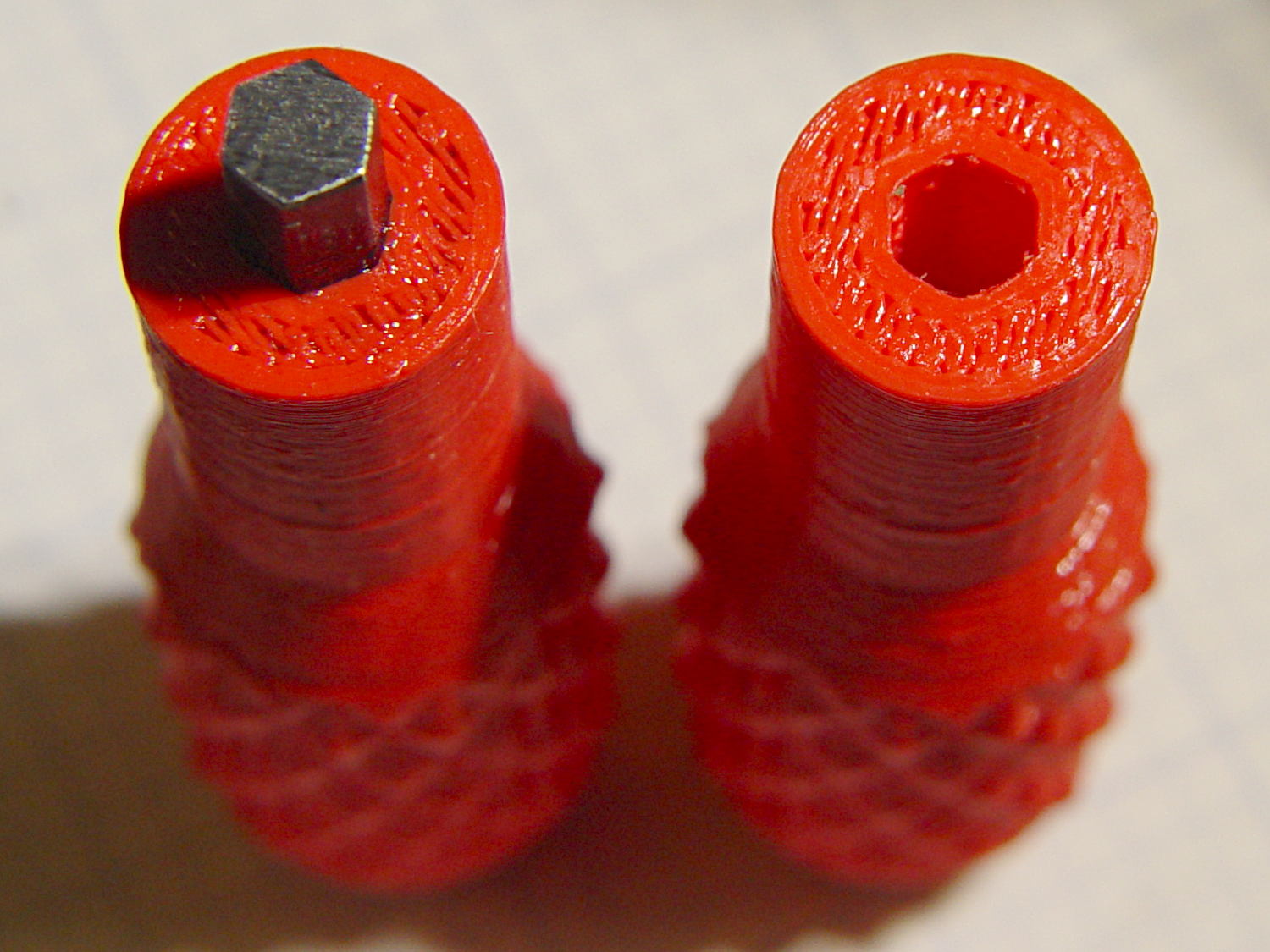
You can see the gap just above the brass anti-backlash nut:
Sherline Z-axis leadscrew nut – top end
At that point, the nut has barely a single micro-smidgen of thread engaged; that last 0.1340 inch of travel (yeah, I measured it) isn’t usable.
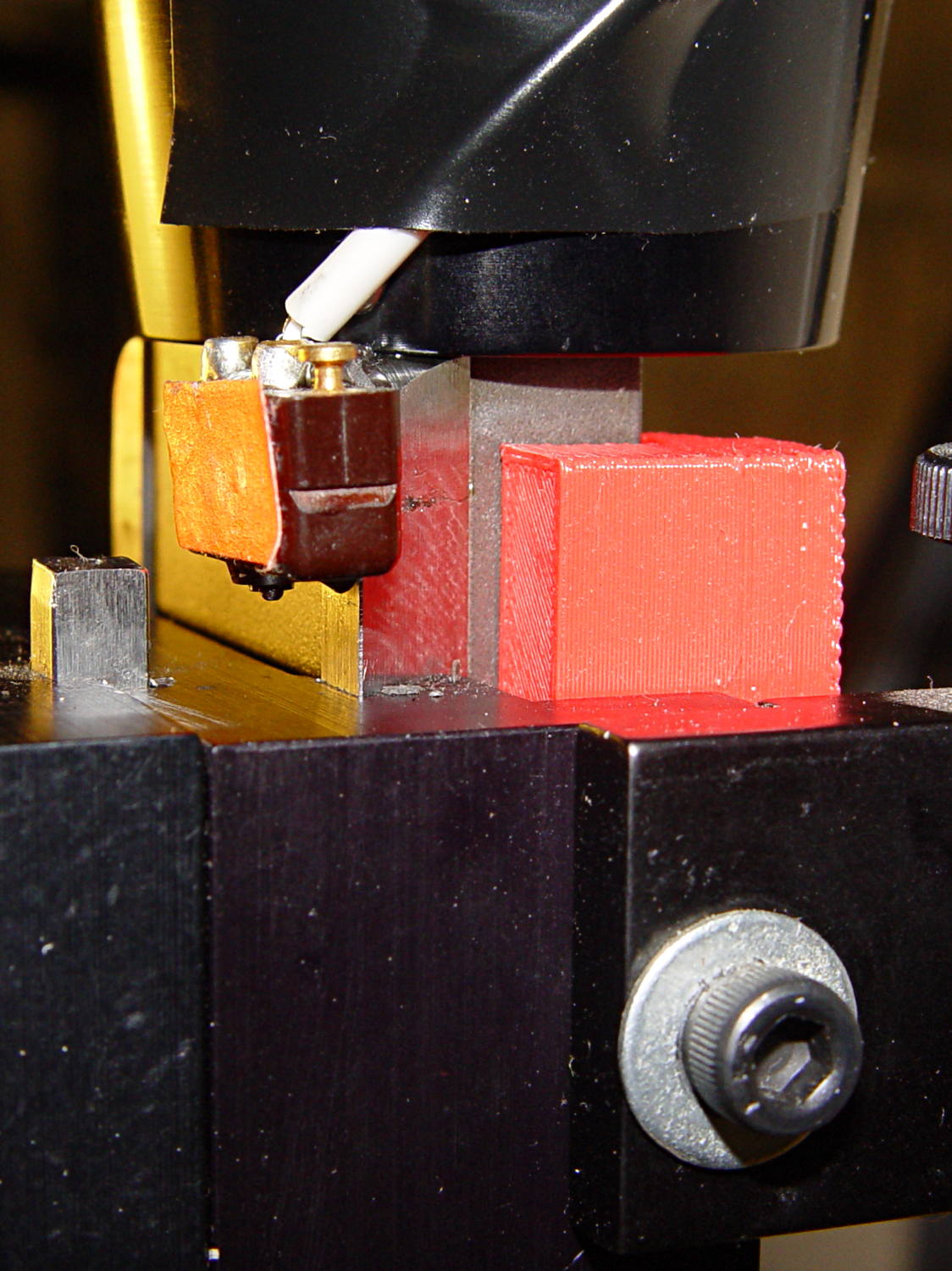
Rather than put a collar around the end of the leadscrew, I opted for a brute-force block atop the Z-axis saddle nut that will slam into the bottom of the stepper motor mount just before the anti-backlash nut disengages:
Sherline Z-axis Overrun Block – rear view
A strip of tapeless sticky (double-sided tape, minus the tape) holds the block in place on the saddle nut. It’s not subject to any particular stress: as long as it doesn’t fall off, it’s all good.
I ran the stage upward until it stalled, then epoxied a new switch (with the old fluorescent tape) in place. This shows the result after backing the stage down a few millimeters:
Sherline Z-axis Overrun Block – side view
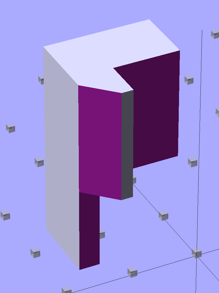
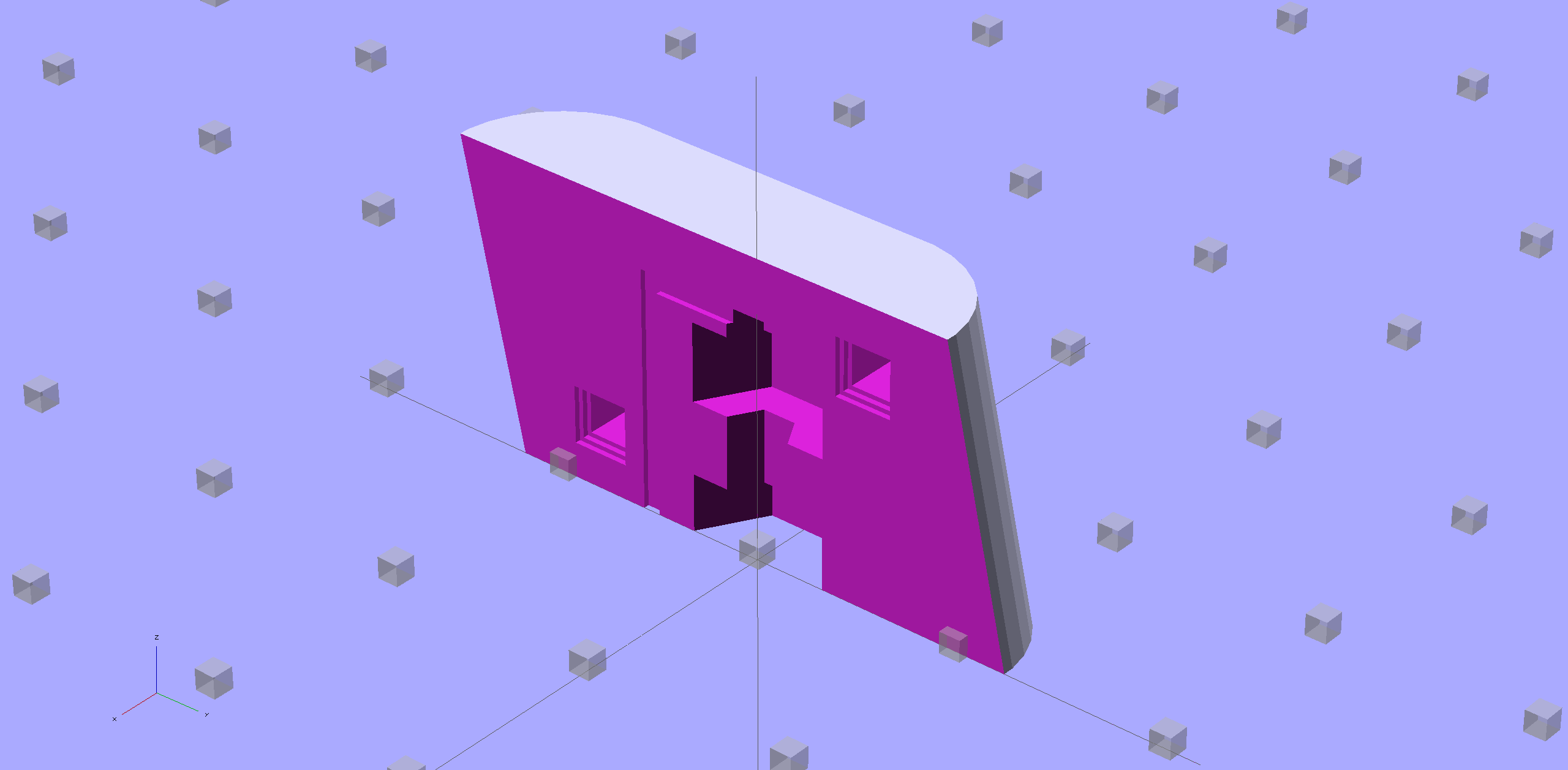
The solid model shows off the bevel that provides a bit more room for anti-backlash nut adjustment, not that I ever adjust it that much:
Sherline Z-Axis Overrun Prevention Block – solid model
Obviously, it doesn’t print in that position, but it’s easier to design it in the natural orientation and flip it around for printing.
The OpenSCAD source code:
// Sherline Z-axis Overrun Prevention Block
// Ed Nisley KE4ZNU December 2013

Layout = "Show";			// Show Build

//- Extrusion parameters must match reality!
//  Print with 2 shells and 3 solid layers

ThreadThick = 0.25;
ThreadWidth = 0.40;

HoleWindage = 0.2;

Protrusion = 0.1;			// make holes end cleanly

//----------------------
// Dimensions

BlockZ = 30.0;				// overall height
ZLimit = 17.0;				// Z travel limit

TongueX = 9.0;				// beside Z axis dovetail
TongueY = 10.0;

StubX = 6.0;				// behind Z axis pillar
StubY = 3.0;

BlockX = TongueX + StubX;	// overall X

TabY = 3.0;					// behind brass bracket
TabX = BlockX - sqrt(2)*TabY;
TabZ = BlockZ - ZLimit;

BlockY = TongueY + StubY + TabY;	// overall Y

//----------------------
// Useful routines

module ShowPegGrid(Space = 10.0,Size = 1.0) {

  Range = floor(50 / Space);

	for (x=[-Range:Range])
	  for (y=[-Range:Range])
		translate([x*Space,y*Space,Size/2])
		  %cube(Size,center=true);

}

//- The Block

module Block() {

	difference() {
		cube([BlockX,BlockY,BlockZ]);

		translate([-Protrusion,-Protrusion,-Protrusion])	// remove column
			cube([(StubX + Protrusion),(TongueY + Protrusion),2*BlockZ]);

		translate([-BlockX/2,-Protrusion,-Protrusion])		// form tab
			cube([2*BlockX,(TongueY + StubY),(TabZ + Protrusion)]);

		translate([0,BlockY,(BlockZ/2 - 0*Protrusion)])
			rotate(45)
				cube([3*StubY,2*StubY,(BlockZ + 2*Protrusion)],center=true);

		translate([0,0,-Protrusion])
			cube([sqrt(2)*TabY,2*BlockY,(TabZ + Protrusion)]);
	}
}

//-------------------
// Build it...

ShowPegGrid();

if (Layout == "Show")
	Block();

if (Layout == "Build")
	translate([-BlockZ/2,-BlockY/2,BlockX])
	rotate([0,90,0])
		Block();
While putting the speed wrenches in the box with the Sherline four-jaw chuck, it occurred to me that I had all the makings of a handle for Sherline’s steel tommy bars:
Sherline Tommy Bar Handle – solid model
Because these are intended for pushing, rather than twisting, I dialed the knurl back to 32 DP, reduced the depth to 0.5 mm, and ran the bar almost all the way through the handle for strength:
Sherline Tommy Bar Handles
A dab of urethane adhesive inside the handle holds the bar in place. They started out a snug slip fit, so we’ll see how well that holds the bars in place.
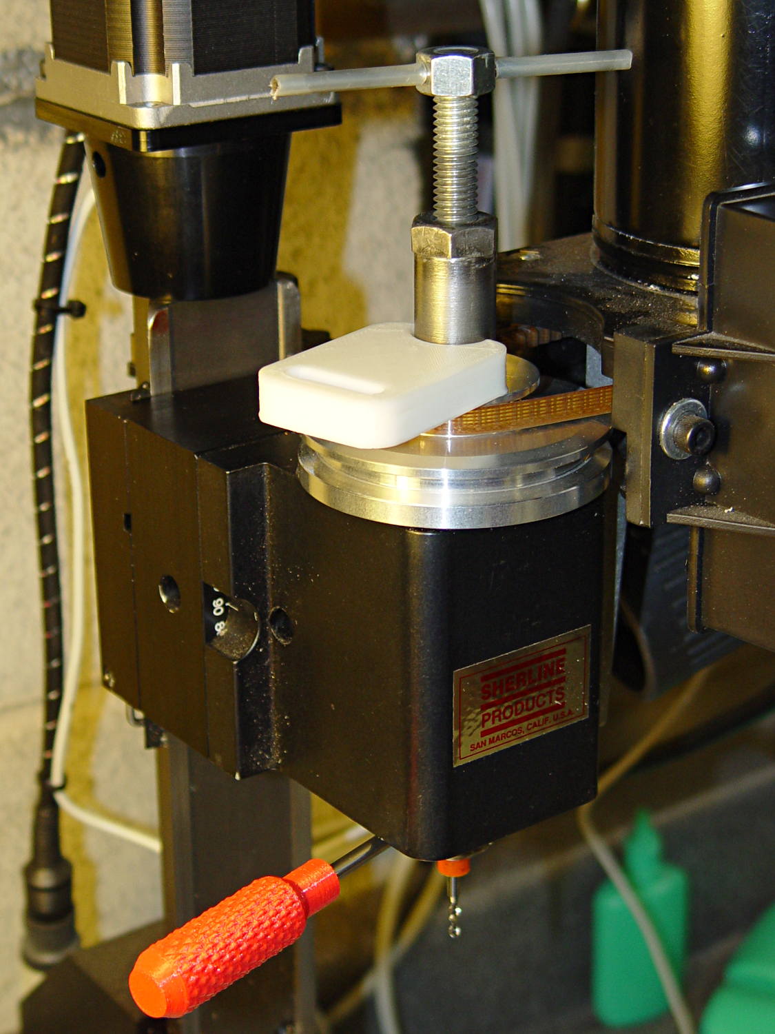
A tommy bar holds the spindle against the torque from the collet pusher:
Sherline CNC mill – tommy bar and collet pusher
A pair will come in handy with the three-jaw chuck the next time that one appears.
The white slab is a very early 3D printed tool from my Thing-O-Matic, made to hold the pin at exactly the proper distance from the pulley so it fits squarely into the pusher and locks it to the spindle:
Locking pin holder – spindle end view
Other folks make much nicer tommy bar handles than mine, but I’d say my 3D printed handles beat a common nail any day!
The OpenSCAD source code:
// Knurled handles for Sherline tommy bars
// Ed Nisley - KE4ZNU - December 2013

use <knurledFinishLib_v2.scad>

//- Extrusion parameters must match reality!
//  Print with 2 shells and 3 solid layers

ThreadThick = 0.20;
ThreadWidth = 0.40;

HoleWindage = 0.2;			// extra clearance

Protrusion = 0.1;			// make holes end cleanly

PI = 3.14159265358979;
inch = 25.4;

//----------------------
// Dimensions

ShaftDia = 10.0;				// un-knurled section diameter
ShaftLength = 10.0;				//  ... length

SocketDia = 4.0;				// tommy bar diameter
SocketDepth = 40.0;

KnurlLen = 35.0;				// length of knurled section
KnurlDia = 15.0;				//   ... diameter
KnurlDPNom = 32;				// Nominal diametral pitch = (# diamonds) / (OD inches)

DiamondDepth = 0.5;				//   ... depth of diamonds
DiamondAspect = 2;				// length to width ratio

NumDiamonds = floor(KnurlDPNom * KnurlDia / inch);
echo(str("Num diamonds: ",NumDiamonds));

NumSides = 4*(NumDiamonds - 1);		// 4 facets per diamond. Library computes diamonds separately!

KnurlDP = NumDiamonds / (KnurlDia / inch);				// actual DP
echo(str("DP Nom: ",KnurlDPNom," actual: ",KnurlDP));

DiamondWidth = (KnurlDia * PI) / NumDiamonds;

DiamondLenNom = DiamondAspect * DiamondWidth;					// nominal diamond length
DiamondLength = KnurlLen / round(KnurlLen/DiamondLenNom);		//  ... actual

TaperLength = 0.75*DiamondLength;

//----------------------
// Useful routines

module PolyCyl(Dia,Height,ForceSides=0) {			// based on nophead's polyholes

  Sides = (ForceSides != 0) ? ForceSides : (ceil(Dia) + 2);

  FixDia = Dia / cos(180/Sides);

  cylinder(r=(FixDia + HoleWindage)/2,
           h=Height,
           $fn=Sides);
}

module ShowPegGrid(Space = 10.0,Size = 1.0) {

  Range = floor(50 / Space);

	for (x=[-Range:Range])
	  for (y=[-Range:Range])
		translate([x*Space,y*Space,Size/2])
		  %cube(Size,center=true);
}

//- Build it

ShowPegGrid();

difference() {
	union() {
		render(convexity=10)
		translate([0,0,TaperLength])
			knurl(k_cyl_hg=KnurlLen,
				  k_cyl_od=KnurlDia,
				  knurl_wd=DiamondWidth,
				  knurl_hg=DiamondLength,
				  knurl_dp=DiamondDepth,
				  e_smooth=DiamondLength/2);
		color("Orange")
		cylinder(r1=ShaftDia/2,
					r2=(KnurlDia - DiamondDepth)/2,
					h=(TaperLength + Protrusion),
					$fn=NumSides);
		color("Orange")
		translate([0,0,(TaperLength + KnurlLen - Protrusion)])
			cylinder(r2=ShaftDia/2,
					r1=(KnurlDia - DiamondDepth)/2,
					h=(TaperLength + Protrusion),
					$fn=NumSides);
		color("Moccasin")
		translate([0,0,(2*TaperLength + KnurlLen - Protrusion)])
			cylinder(r=ShaftDia/2,h=(ShaftLength + Protrusion),$fn=NumSides);

	}
	translate([0,0,(2*TaperLength + KnurlLen + ShaftLength - SocketDepth + Protrusion)])
		PolyCyl(SocketDia,(SocketDepth + Protrusion),6);
}
Browning Hi-Power Magazine Block – solid model – whole
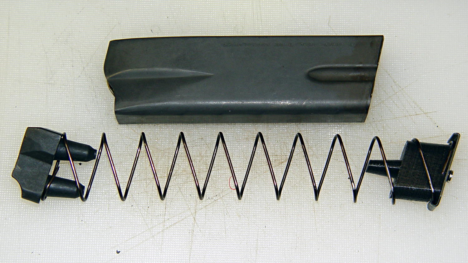
The horn fits between the follower’s pegs, so that chopping the pegs off won’t increase the magazine’s capacity. Chopping the horn off without modifying the follower won’t make any difference, either. As nearly as I can tell, chopping the pegs off the follower will destabilize it enough that it’ll roll over atop the spring, but I admit to not actually trying that.
The yellow comb supports the overhang that captures the tab around the magazine spring and there’s a tiny support spider inside the lower nut clearance that holds the ceiling in place:
Browning Hi-Power Magazine Block – solid model – section
The inner nut trap probably droops a bit without any support, but there’s no way to tell when it’s printed as one solid piece. That trap will hold the blob of steel-filled epoxy that secures the screw and helps prevent the block from turning, so it’s not really a nut trap and doesn’t require a precision fit. The vent tube from the top of the screw shaft gives the air and any excess epoxy an exit path.
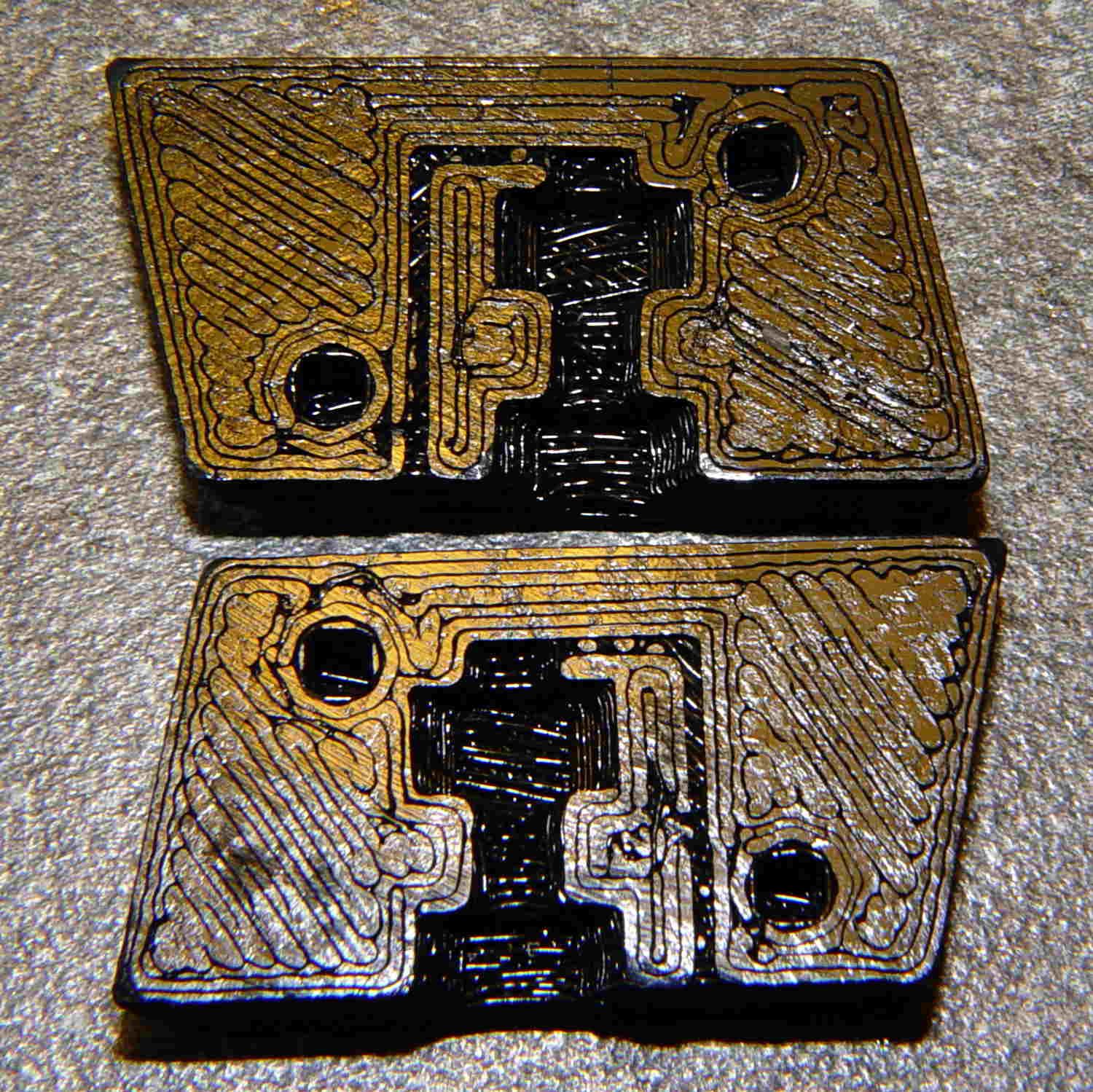
Here’s a bottom view of two blocks, showing the support structures and the results:
Browning Hi-Power magazine – block support detail
I poked the tips of a snap ring pliers into the spider and twisted it out. The comb snaps off with fingernail pressure.
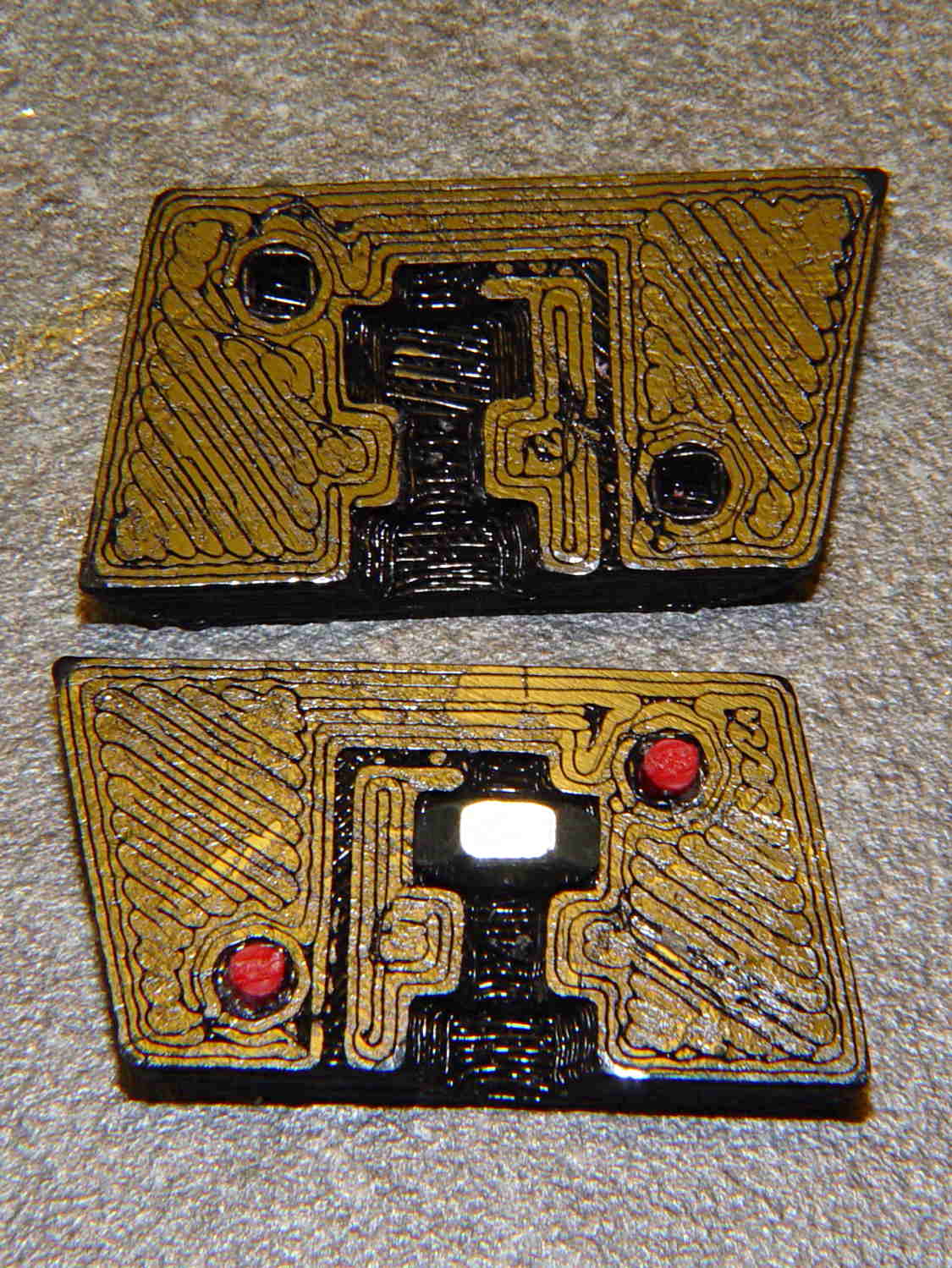
You could also print it without support by laying it flat, then glue the halves together with alignment pins. This is a bottom view:
Browning Hi-Power Magazine Block – solid model – split bottom
The OpenSCAD program has a handful of configuration settings that determine which of those blocks it produces, which components appear, and how it’s oriented.
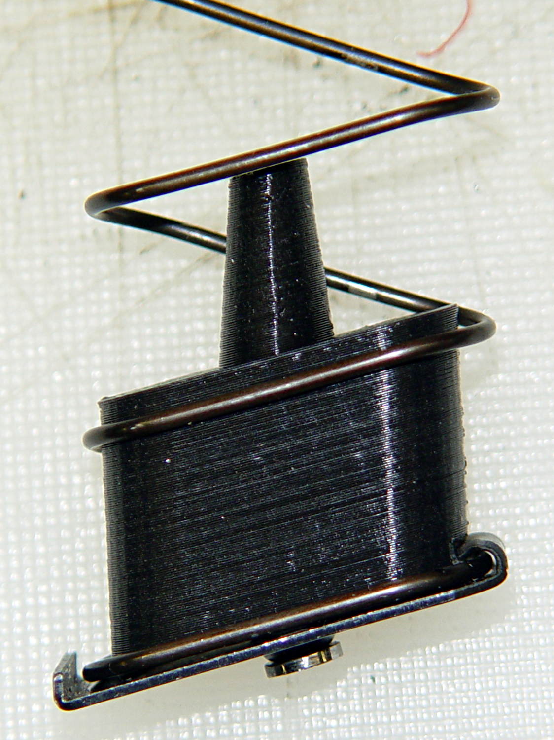
Installed in a Browning magazine, the block looks like this:
Browning Hi-Power magazine – block in place
A detail of the bottom shows the notch capturing the spring tab:
Browning Hi-Power magazine – block detail
I think the top surface would benefit from a small bevel to ease the spring around the block, but that’s in the nature of fine tuning.
Not having heard back from my legislators yet, I still don’t know whether this counts as a readily reversible modification. I have my doubts, what with it being plastic and all, but we shall see.
The OpenSCAD source code:
// Browning Hi-Power Magazine Block
// Ed Nisley KE4ZNU December 2013

Layout = "Whole";			// Show Whole Split
							//  Show = section view for demo, not for building
							//  Whole = upright for steel or plastic
							//  Split = laid flat for plastic show-n-tell assembly

AlignPins = (Layout == "Split");					// pins only for plastic show-n-tell

Support = (Layout != "Split");						// no support for split

//- Extrusion parameters must match reality!
//  Print with 2 shells and 3 solid layers

ThreadThick = 0.15;
ThreadWidth = 0.40;

HoleWindage = 0.2;

Protrusion = 0.1;			// make holes end cleanly

//----------------------
// Dimensions

Angle = 12.5;				// from vertical

SpringID = 10.3;			// magazine spring curvature (measure with drill shank)
SpringRadius = SpringID / 2;

Length = 24.0;				// front-to-back perpendicular to magazine shaft
Height = 18.0;				// bottom-to-top, parallel to magazine shaft
							//  18 = 10 round capacity

RectLength = Length - SpringID;	// block length between end radii

HornBaseOD = 8.0;			// fits between follower pegs to prevent shortening
HornTipOD = 5.0;
HornAddTip = (HornTipOD/2)*tan(Angle);
HornAddBase = (HornBaseOD/2)*tan(Angle);
HornAddLength = HornAddTip + HornAddBase + 2*Protrusion;
HornLength = 12.0;			// should recompute ODs, but *eh*

TrimHeight = 2.5;			// vertical clearance for spring clip on base plate
							//   OEM = 2.5
							//   generic A = 2.5

TrimInset = 1.5;			// ... horizontal
							//	 OEM = 0.0
							//   generic A = 1.5

ScrewOD = 3.0 - 0.25;		// screw hole dia - minimal thread engagement
ScrewLength = 11.0;
ScrewOffset = -1.5;			//   ... from centerline
							//  OEM = 0.0
							//  generic A = -1.5

NutOD = 5.6;				// hex nut dia across flats
NutThick = 2.4;				//  ... then add 50% to trap for thread engagement & epoxy
NutOffset = 6.0;			//  ... base height from floor

VentDia = 2.0;				// air vent from back of screw recess

PinOD = 1.72;				// alignment pins
PinLength = 6.0;
PinInset = 0.6*SpringRadius;	// from outside edges
echo(str("Alignment pin length: ",PinLength));

NumSides = 8*4;				// default cylinder sides

Offset = 5.0/2;				// from centerline for build layout

//----------------------
// Useful routines

function Delta(a,l) = l*tan(a);				// incremental length due to angle

// Locating pin hole with glue recess
//  Default length is two pin diameters on each side of the split

module LocatingPin(Dia=PinOD,Len=0.0) {

	PinLen = (Len != 0.0) ? Len : (4*Dia);

	translate([0,0,-ThreadThick])
		PolyCyl((Dia + 2*ThreadWidth),2*ThreadThick,4);

	translate([0,0,-2*ThreadThick])
		PolyCyl((Dia + 1*ThreadWidth),4*ThreadThick,4);

	translate([0,0,-(Len/2 + ThreadThick)])
		PolyCyl(Dia,(Len + 2*ThreadThick),4);

}

module PolyCyl(Dia,Height,ForceSides=0) {			// based on nophead's polyholes

  Sides = (ForceSides != 0) ? ForceSides : (ceil(Dia) + 2);

  FixDia = Dia / cos(180/Sides);

  cylinder(r=(FixDia + HoleWindage)/2,
           h=Height,
	   $fn=Sides);
}

module ShowPegGrid(Space = 10.0,Size = 1.0) {

  Range = floor(50 / Space);

	for (x=[-Range:Range])
	  for (y=[-Range:Range])
		translate([x*Space,y*Space,Size/2])
		  %cube(Size,center=true);

}

//----------------------
// The magazine block

module Block(SectionSelect = 0) {

CropHeight = Height*cos(Angle);				// block height perpendicular to base
echo(str("Perpendicular height: ",CropHeight));

	difference() {
		union() {
			intersection() {
				rotate([Angle,0,0])
					hull() {
						for (i=[-1,1])
							translate([0,i*RectLength/2,-((Length/2)*sin(Angle) + Protrusion)])						cylinder(r=SpringRadius,
										h=(Height + 2*(Length/2)*sin(Angle) + 2*Protrusion),
										$fn=NumSides);
					}
				translate([0,0,CropHeight/2])
					cube([2*SpringID,3*Length,CropHeight],center=true);
			}
			translate([0,-Height*sin(Angle),Height*cos(Angle)])
				resize([SpringID,0,0])
					intersection() {
						rotate([Angle,0,0])
							translate([0,0,-(HornAddBase + Protrusion)])
								cylinder(r1=HornBaseOD/2,
										r2=HornTipOD/2,
										h=(HornLength + HornAddLength + Protrusion),
										$fn=NumSides);
					cube([2*SpringID,Length,2*(HornLength*cos(Angle) + Protrusion)],center=true);
				}
		}

		translate([0,ScrewOffset,-Protrusion])		// screw
			rotate(180/6)
				PolyCyl(ScrewOD,(ScrewLength + Protrusion),6);

		translate([0,ScrewOffset,NutOffset])		// nut trap in center
			rotate(180/6)
				PolyCyl(NutOD,1.5*NutThick,6);

		translate([0,ScrewOffset,-Protrusion])		// nut clearance at base
			rotate(180/6)
				PolyCyl(NutOD,(1.1*NutThick + Protrusion),6);

		translate([SpringID/2,-((Length/2)/cos(Angle) - TrimInset),-Protrusion])
			rotate(180)
				cube([SpringID,2*TrimInset,(TrimHeight + Protrusion)],center=false);

		if (AlignPins)								// alignment pins
			for (i=[-1,1])
				rotate([Angle,0,0])
				translate([0,
							(i*((Length/2)*cos(Angle) - PinInset)),
							(CropHeight/2 - i*2*PinInset)])
					rotate([0,90,0]) rotate(45 - Angle)
						LocatingPin(PinOD,PinLength);

		translate([0,(ScrewOffset - NutOD),-Protrusion])	// air vent
			rotate(180/8)
				PolyCyl(VentDia,(ScrewLength + Protrusion),8);
		translate([0,(ScrewOffset + VentDia/2),ScrewLength])
			rotate([90,0,0]) rotate(180/8)
				PolyCyl(VentDia,(NutOD + VentDia),8);

		if (SectionSelect == 1)
			translate([0*SpringID,-2*Length,-Protrusion])
				cube([2*SpringID,4*Length,(Height + HornLength + 2*Protrusion)],center=false);
		else if (SectionSelect == -1)
			translate([-2*SpringID,-2*Length,-Protrusion])
				cube([2*SpringID,4*Length,(Height + HornLength + 2*Protrusion)],center=false);

	}

	NumBars = floor((SpringID/2)/(5*ThreadWidth));

	if (Support) {									// add support structures
		for (i = [-NumBars:NumBars])
			translate([i*5*ThreadWidth,
					   -((Length/2)/cos(Angle) + TrimInset/2 + ThreadWidth),
					   (TrimHeight - ThreadThick)/2])
				color("Yellow")
				cube([(2*ThreadWidth),(3*TrimInset),(TrimHeight - ThreadThick)],center=true);

		translate([-SpringID/2,-((Length/2)/cos(Angle) + 2*TrimInset + ThreadWidth),0])
			color("Yellow")
			cube([SpringID,(2*ThreadWidth),(TrimHeight - ThreadThick)],center=false);

		translate([0,ScrewOffset,0])
			for (j=[0:5]) {
			rotate(30 + 360*j/6)
				translate([(NutOD/2 - ThreadWidth)/2,0,(1.1*NutThick - ThreadThick)/2])
					color("Yellow")
					cube([(NutOD/2 - ThreadWidth),
						  (2*ThreadWidth),
						  (1.1*NutThick - ThreadThick)],
						  center=true);
        }
	}

}

//-------------------
// Build it...

ShowPegGrid();

if (Layout == "Show")
	Block(1);

if (Layout == "Whole")
	Block(0);

if (Layout ==  "Split") {
	translate([(Offset + Length/2),Height/2,0])
		rotate(90) rotate([0,-90,-Angle])
			Block(-1);
	translate([-(Offset + Length/2),Height/2,0])
		rotate(-90) rotate([0,90,Angle])
			Block(1);
}
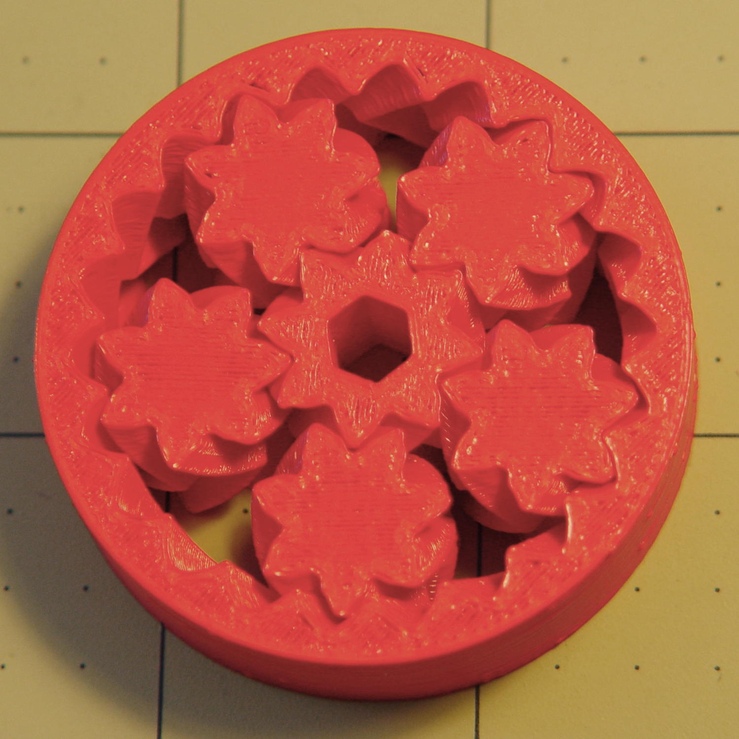
A Home Shop Machinist article (A Speed Key for Your Four-Jaw Chuck, p 67 Nov-Dec 2013, David Morrow) showed some lovely knurled steel knobs. These 3D printed knobs aren’t nearly as pretty, but they do much the same thing:
Sherline Knobs – in 4 jaw chuck
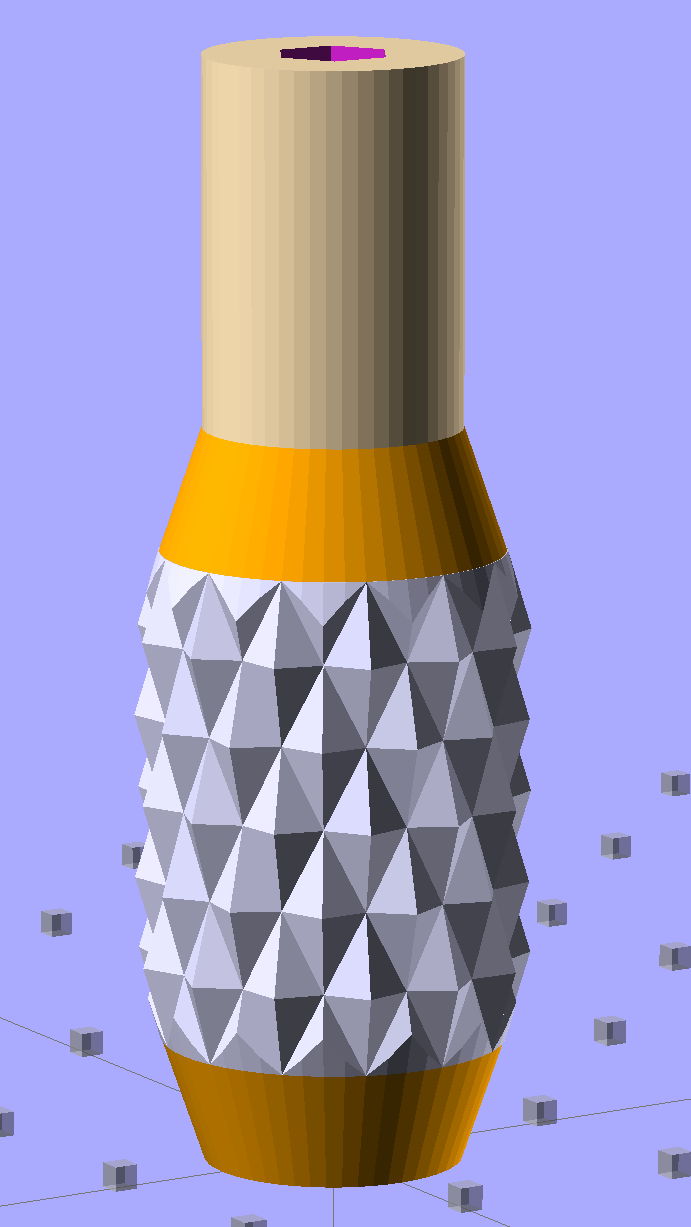
The solid model resembles the illegitimate offspring of a wine bottle and a pineapple:
Sherline Knob – solid model
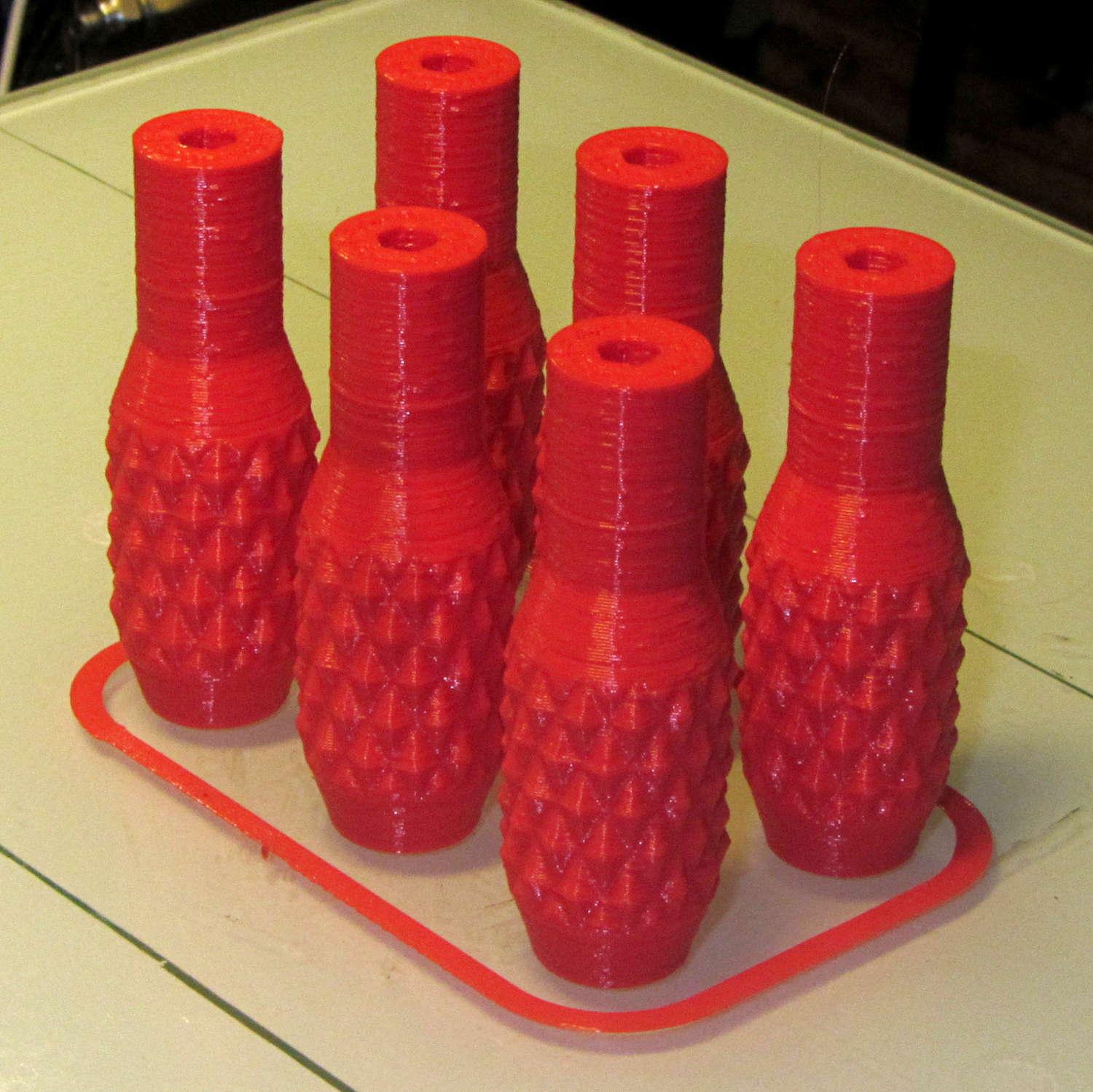
The knurling comes from aubenc’s Knurled Surface Library v2. I ran off a prototype (on the left), then tweaked the dimensions to get the final version on the right:
Sherline Knobs – knurl depth variation
Being that type of guy, I define the knurl in terms of its diametral pitch, compute the diamond width & length to fit in the available space, then hand those measurements to the knurling library… which recomputes everything and decides on one less diamond than I do: NumSides has a Finagle Constant of -1 to make the answer come out right. We may be using a different diameter or something, but I haven’t deciphered the source code. It’s parametric out the wazoo, as usual, so you can spin up what you like, how you like it.
Anyhow, a 24 DP knurl with 1.0 mm depth looks and feels pretty good; the XY resolution isn’t good enough for a 48 DP knurl around that knob diameter. The diamonds don’t come out as crisp and pointy as crushed steel knurls, but they’re OK for my fingers.
Doing half a dozen doesn’t take much longer than doing a few, because there’s a 20 second minimum layer time in effect and those things don’t have much plastic, so now I have one for the hold-down clamps and another for Show-n-Tell sessions:
Sherline Knobs – M2 platform
I chopped a 5/32 inch hex key into five 15 mm lengths with a Dremel cutoff wheel, then filed both ends flat and broke the edges. The hex stubs were a press fit in the hex holes, so I finger-started them, grabbed the hex in the drill press, aligned the handle below, and rammed the stub about 5 mm deep. The final depth comes from jamming the wrench into the chuck and pressing firmly, so the stubs project exactly as far as possible:
Sherline Knobs – hex key inserted
One might quibble about the infill on the end; one may go adjust one’s own printer as one prefers.
There’s 0.1 mm more HoleWindage than usual, because these holes must fix a hex shaft, not a circular pin, and the corners need some clearance. They came out a firm press fit: exactly what’s needed.
They’re no good for final tightening of those chuck jaws, but that’s not their purpose…
The general idea is to reduce the capacity of a 13 round Browning Hi-Power magazine to 10 rounds, in compliance with the NY Safe Act, using a number of possibly invalid assumptions. The new Firearms tag will produce earlier posts.
This early prototype tried out the sizes, shapes, and angles, using an M3x0.5 socket head cap screw:
The bottom nut trap locates the block on the inner floor plate by capturing the nut. It might need a bit more clearance or a chamfer to allow for brazing material around the nut flats; cleaning up the brazed nut with a file might also help.
The central trap holds a nut that anchors the block; the trap must be about 50% longer than the nut to allow for thread alignment, because the central hole is a loose tap fit.
That central nut probably isn’t needed, because you’d fill the central shaft with metal-loaded epoxy, which would form a perfectly serviceable, exactly form-fitting, and utterly non-removable “nut”. The vent from the end of the screw shaft releases air trapped behind the epoxy by the screw; if you don’t have a vent, then air pressure will force the epoxy out of the cavity.
If the epoxy “nut” is workable, then you can build it in a single piece printed vertically on the platform. Having a split version makes it easier to show off and, in truth, the cemented joint is about as strong as the rest of the object.
Hot off the M2 3D printer, it looks like this:
BHP magazine block – prototype nut trap – bare
A few threads droop into the air vent, so that channel should be larger. The overall plastic block may be porous enough to release the air pressure even without a vent.
With locating pins glued in place and a nut in the central trap:
BHP magazine block – prototype nut trap
Pretty much as I expected, it doesn’t quite fit in the magazine, because it doesn’t have clearance for the little tab on the inner floor plate that captures the spring.
One might argue that a plastic block isn’t “permanent”, but it’s definitely not “readily” removed:
PLA doesn’t dissolve in common solvents
It doesn’t actually melt and flow away at high temperatures
It’s protected by the spring and inner floor plate
It’s certainly strong enough to resist simple mechanical attacks
This is a start…
The OpenSCAD source code, replete with inadequacies:
// Browning Hi-Power Magazine Plug
// Ed Nisley KE4ZNU November 2013

Layout = "Show";			// Show Whole Pin Build

CrossSection = 1;			// -1, 0, 1 to select section side or none

Section = (Layout == "Build") ? 1 : CrossSection;		// for cross-section for build

//- Extrusion parameters must match reality!
//  Print with 2 shells and 3 solid layers

ThreadThick = 0.25;
ThreadWidth = 0.40;

HoleWindage = 0.2;

Protrusion = 0.1;			// make holes end cleanly

//----------------------
// Dimensions

Angle = 12.5;				// from vertical

EndDia = 10.3;				// an 11/32 inch drill fits
EndRadius = EndDia / 2;

Length = 24.0;				// front-to-back perpendicular to magazine shaft
Height = 14.0;				// bottom-to-top, parallel to magazine shaft
							//  14 = 10 round capacity
							//  28 = 7 round

RectLength = Length - EndDia;	// block length between end radii

ScrewOD = 3.0 - 0.5;		// bottom screw tapping diameter
ScrewLength = 11.0;
ScrewOffset = 0;			//   ... from centerline

NutOD = 5.5;				// hex nut dia across flats
NutThick = 2.4;				//  ... then add 50% for thread engagement & epoxy
NutOffset = 6.0;			//  ... base height from floor

VentWidth = 2*ThreadWidth;	// air vent from back of screw recess
VentDepth = 4*ThreadThick;

NumSides = 8*4;				// default cylinder sides

PinOD = 1.72;				// alignment pins
PinLength = 6.0;
PinInset = 0.9*EndRadius;	// from outside edges
echo(str("Alignment pin length: ",PinLength));

Offset = 5.0/2;				// from centerline for build layout

//----------------------
// Useful routines

// Locating pin hole with glue recess
//  Default length is two pin diameters on each side of the split

module LocatingPin(Dia=PinOD,Len=0.0) {

	PinLen = (Len != 0.0) ? Len : (4*Dia);

	translate([0,0,-ThreadThick])
		PolyCyl((Dia + 2*ThreadWidth),2*ThreadThick,4);

	translate([0,0,-2*ThreadThick])
		PolyCyl((Dia + 1*ThreadWidth),4*ThreadThick,4);

	translate([0,0,-(Len/2 + ThreadThick)])
		PolyCyl(Dia,(Len + 2*ThreadThick),4);

}

module PolyCyl(Dia,Height,ForceSides=0) {			// based on nophead's polyholes

  Sides = (ForceSides != 0) ? ForceSides : (ceil(Dia) + 2);

  FixDia = Dia / cos(180/Sides);

  cylinder(r=(FixDia + HoleWindage)/2,
           h=Height,
	   $fn=Sides);
}

module ShowPegGrid(Space = 10.0,Size = 1.0) {

  Range = floor(50 / Space);

	for (x=[-Range:Range])
	  for (y=[-Range:Range])
		translate([x*Space,y*Space,Size/2])
		  %cube(Size,center=true);

}

//----------------------
// Components

module Block(SectionSelect = 0) {

Delta = tan(Angle)*(Length/2);				// incremental length due to angle

CropHeight = Height*cos(Angle);				// block height perpendicular to base

echo(str("Perpendicular height: ",CropHeight));

	difference() {
		intersection() {
			rotate([Angle,0,0])
				difference() {
					translate([0,0,-Height/2])
						linear_extrude(height=2*Height,convexity=2) {
							for (i=[-1,1])
								translate([0,(i*RectLength/2),0])
									rotate(180/NumSides)
										circle(r=EndRadius/cos(180/NumSides),
												$fn=NumSides);
							square([EndDia,RectLength],center=true);
						}
					for (i=[-1,1])
						translate([0,
									(i*(Length/2 - PinInset)),
									(CropHeight/2 + i*(CropHeight/2 - PinInset))])
							rotate([0,90,0]) rotate(45-Angle)
								LocatingPin(PinOD,PinLength);
				}
			translate([0,0,CropHeight/2])
				cube([2*EndDia,3*Length,CropHeight],center=true);
		}
		translate([0,ScrewOffset,-Protrusion])		// screw
			rotate(180/6)
				PolyCyl(ScrewOD,(ScrewLength + Protrusion),6);

		translate([0,ScrewOffset,NutOffset])		// nut trap in center
			rotate(180/6)
				PolyCyl(NutOD,1.5*NutThick,6);

		translate([0,ScrewOffset,-Protrusion])		// nut clearance at base
			rotate(180/6)
				PolyCyl(NutOD,(1.1*NutThick + Protrusion),6);

		translate([0,-(ScrewOffset + NutOD),(ScrewLength - Protrusion)/2])	// air vent
			cube([VentDepth/2,VentWidth,(ScrewLength + Protrusion)],center=true);
		translate([0,(ScrewOffset - NutOD/2),(ScrewLength - VentWidth/2)])
			cube([VentDepth/2,NutOD,VentWidth],center=true);

		if (SectionSelect == 1)
			translate([EndDia,0,Height/2-Protrusion])
				cube([2*EndDia,3*Length,Height+2*Protrusion],center=true);
		else if (SectionSelect == -1)
			translate([-EndDia,0,Height/2-Protrusion])
				cube([2*EndDia,3*Length,Height+2*Protrusion],center=true);
	}

}

//-------------------
// Build it...

ShowPegGrid();

if (Layout == "Pin")
	LocatingPin(PinOD,PinLength);

if (Layout == "Show")
	Block(CrossSection);

if (Layout == "Whole")
	Block(0);

if (Layout ==  "Build") {
	translate([(Offset + Length/2),Height/2,0])
		rotate(90) rotate([0,-90,-Angle])
			Block(-1);
	translate([-(Offset + Length/2),Height/2,0])
		rotate(-90) rotate([0,90,Angle])
			Block(1);
}
Those simple floor brush strips for the Samsung vacuum cleaner worked moderately well, but the urethane adhesive didn’t have enough grip on the plastic strips. Having just run out of that batch, I made up another set with slightly undercut holes:
Bushing Solid Model – better holes – bottom
That’s half a thread width on each side, just enough to give the adhesive something to grab. Such is the plan, anyway.
I taped the strips to a pair of credit cards (actually, flat cards without embossed characters), slathered a thin layer of urethane atop them, and laid on squares of the same wool fabric I used the last time:
Samsung vacuum floor strips – gluing
Then I piled a steel block atop an aluminum slab on both arrays, fast forwarded a day, peeled and flexed and cut the strips apart:
Samsung floor brushes – glued
The urethane foamed through the holes as I hoped and (seems to have) locked the fabric in place, at least well enough to withstand some experimental bending on the workbench.
Now, to see how they stand up to actual use…
The OpenSCAD source code:
// Samsung Vacuum cleaner nozzle floor strips
// Ed Nisley KE4ZNU January 2013
//  November 2013 - adapt to M2, enlarge holes

Layout = "Build";			// Show, Build

//- Extrusion parameters must match reality!
//  Print with +0 shells and 3 solid layers

ThreadThick = 0.25;
ThreadWidth = 0.4;

HoleWindage = 0.75;

function IntegerMultiple(Size,Unit) = Unit * ceil(Size / Unit);

Protrusion = 0.1;           // make holes end cleanly

//----------------------
// Dimensions

Body = [6.0,59.0,3*ThreadThick];	// width, length, thick

Tab1 = [4.5,5.0,0.0];				// width, length, offset from centerline
Tab2 = [3.5,5.0,0.5];

HoleOC = 8.0;						// adhesive anchoring holes
HoleDia = 2.0;
HoleSides = 4;
HoleMax = floor(Body[1]/(2*HoleOC));

echo("HoleMax: ",HoleMax);

//----------------------
// Useful routines

module PolyCyl(Dia,Height,ForceSides=0) {           // based on nophead's polyholes

Sides = (ForceSides != 0) ? ForceSides : (ceil(Dia) + 2);

FixDia = Dia / cos(180/Sides);

cylinder(r=(FixDia + HoleWindage)/2,
         h=Height,
         $fn=Sides);
}

module ShowPegGrid(Space = 10.0,Size = 1.0) {

    Range = floor(50 / Space);

    for (x=[-Range:Range])
        for (y=[-Range:Range])
            translate([x*Space,y*Space,Size/2])
            %cube(Size,center=true);

}

module BackingStrip() {

	difference() {
		union() {
			translate([0,0,Body[2]/2])
			cube(Body,center=true);
			translate([Tab1[2],-1*Body[1]/2,Body[2]/2])
			cube([Tab1[0],2*Tab1[1],Body[2]],center=true);
			translate([Tab2[2],+1*Body[1]/2,Body[2]/2])
			cube([Tab2[0],2*Tab2[1],Body[2]],center=true);
		}
		for (i = [-HoleMax:HoleMax])
			translate([0,i*HoleOC,-Protrusion])
			rotate(45) {
				PolyCyl(HoleDia,(Body[2] + 2*Protrusion),HoleSides);
				PolyCyl((HoleDia + ThreadWidth),(ThreadThick + Protrusion),HoleSides);
			}
	}
}

//----------------------
// Build it!

ShowPegGrid();

if (Layout == "Show")
	BackingStrip();

if (Layout == "Build")
	rotate(90) BackingStrip();