The Smell of Molten Projects in the Morning

Ed Nisley's Blog: Shop notes, electronics, firmware, machinery, 3D printing, laser cuttery, and curiosities. Contents: 100% human thinking, 0% AI slop.

Tag: M2

Using and tweaking a Makergear M2 3D printer

  • Sony NP-BX1 Battery Test Fixture

    The Sony HDR-AS30V “action camera” uses NP-BX1 lithium batteries (3.7 V @ 1.24 A·h = 4.6 W·h) that are, of course, a completely different size and shape than any other lithium battery on the planet.

    So.

    Tweaking a few dimensions in the Canon NB-6L source code, tinkering with the layout of the contact pins, and shazam Yet Another 3D Printed Battery Test Fixture:
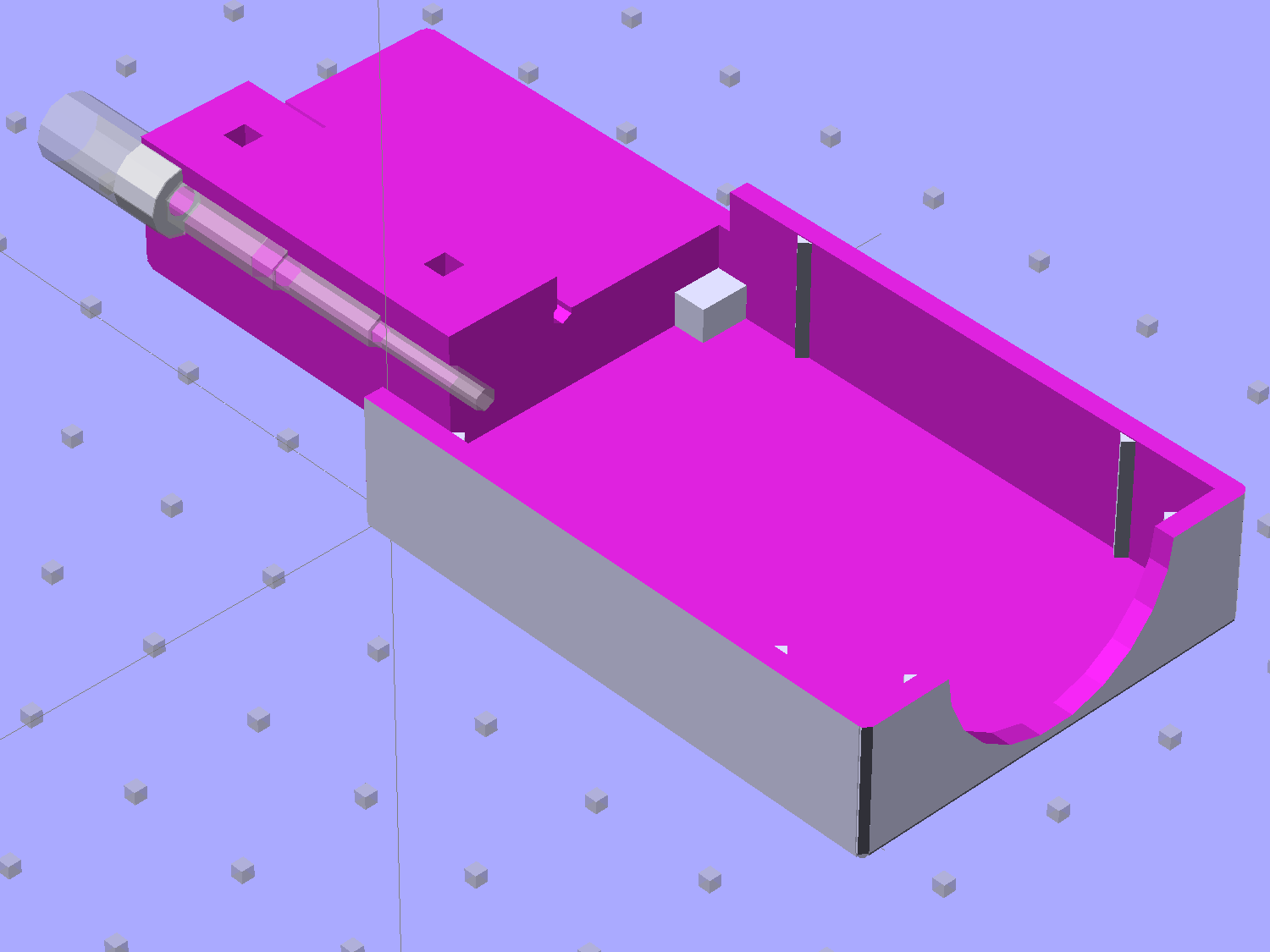
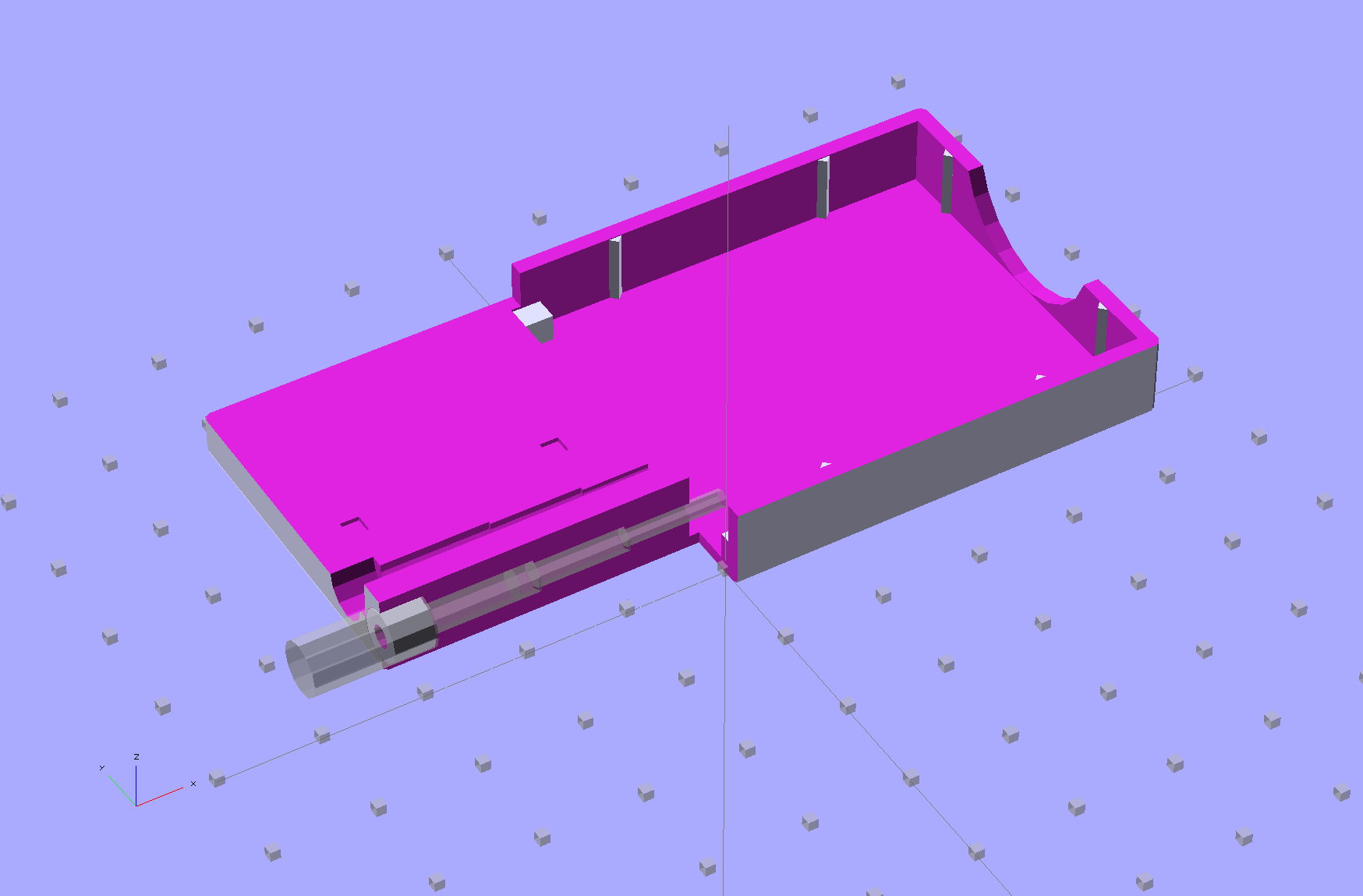
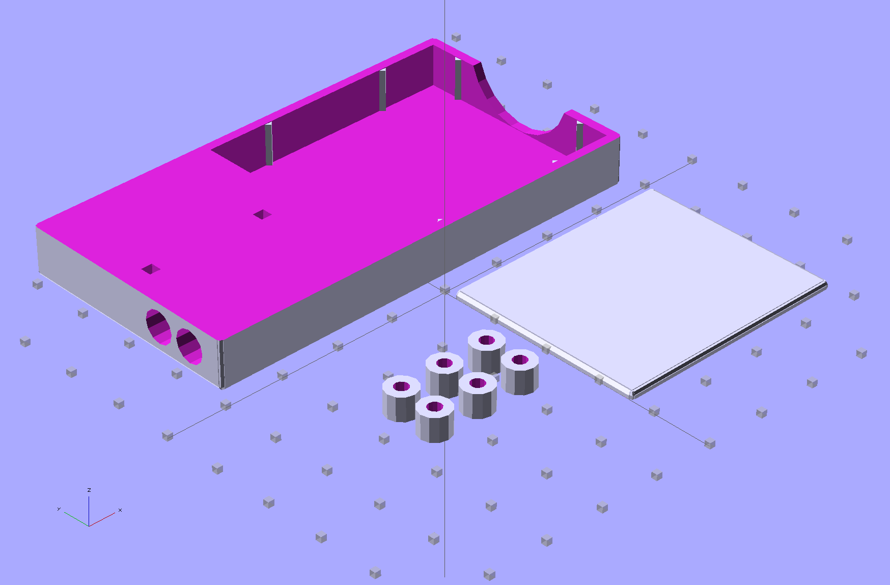
    NP-BX1 Holder - show layout
    NP-BX1 Holder – show layout

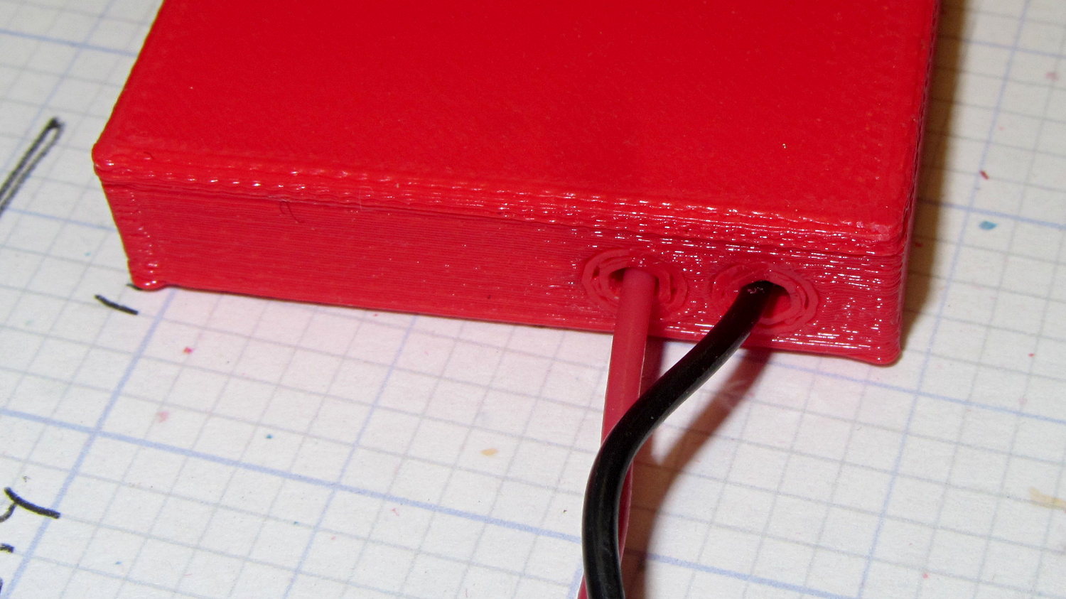
    It builds nicely, although the contact pin tunnels are a bit too close to the top of the case:

    Sony NP-BX1 Holder - on platform
    Sony NP-BX1 Holder – on platform

    After reaming out the contact pin holes to the proper diameters & depths, then gluing the plugs in place, it works just as you’d expect:

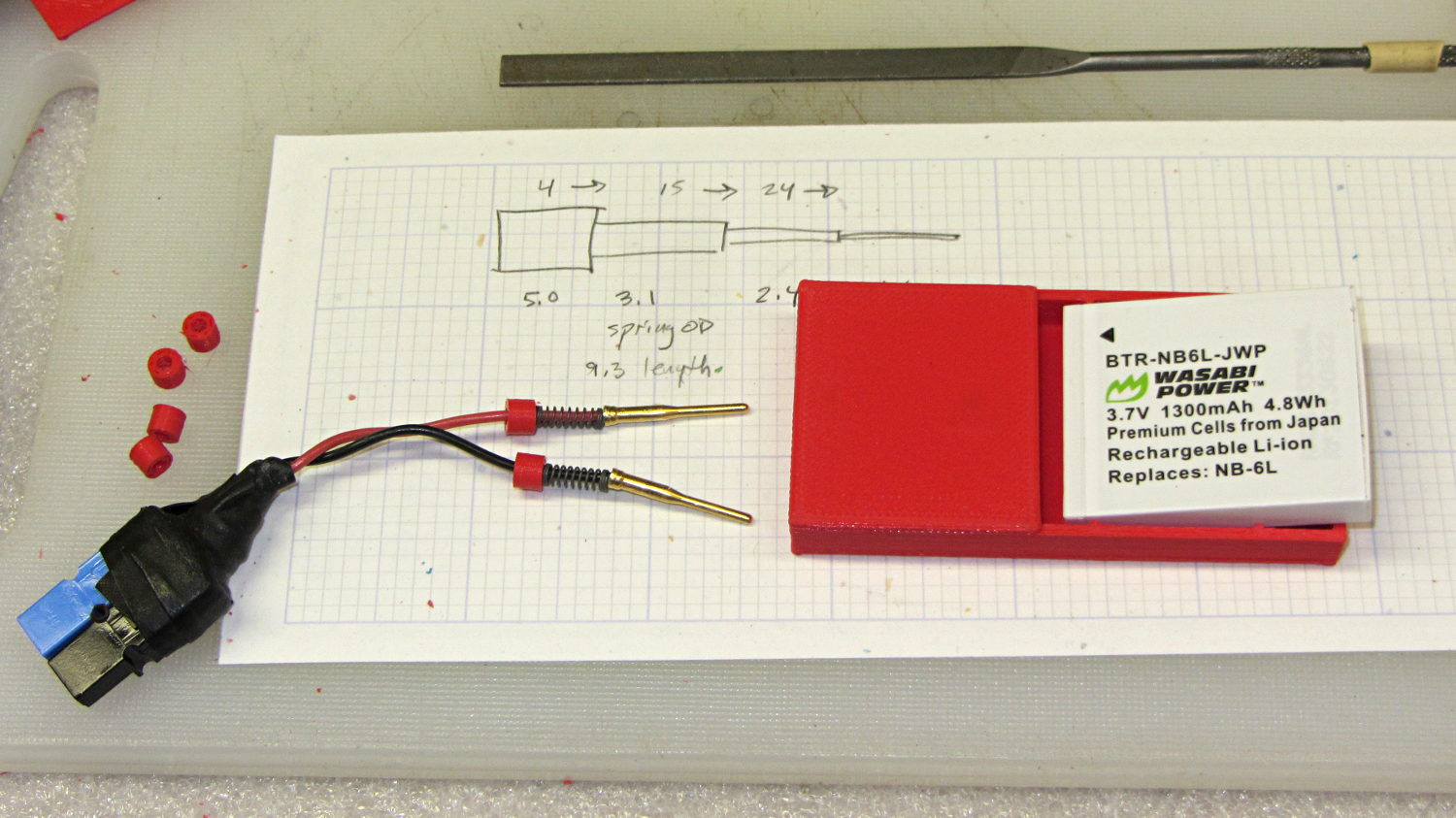
    Sony NP-BX1 battery holder
    Sony NP-BX1 battery holder

    It’s worth noting that the Wasabi charger accepts the batteries upside-down, with the conspicuous chevron against the charger body. It’s definitely not the way all the other chargers work. The keying recesses on the battery (corresponding to the blocks in the solid model) lie along the bottom edge of the contact surface, so flipping the battery over means they’ll hold it in place, but … oh, well.

    That grotty Powerpole connector last saw use in some random benchtop lashup. At some point I’ll be forced to start making more of those.

    The OpenSCAD source code:

    // Holder for Sony NP-BX1 Li-Ion battery
    // Ed Nisley KE4ZNU January 2013
    
    include <MCAD/boxes.scad>
    
    // Layout options
    
    Layout = "Show";					//  Show Build Fit Case Lid Pins Plugs AlignPins
    
    //- Extrusion parameters - must match reality!
    //  Print with +2 shells and 3 solid layers
    
    ThreadThick = 0.20;
    ThreadWidth = 0.40;
    
    HoleWindage = 0.2;
    
    function IntegerMultiple(Size,Unit) = Unit * ceil(Size / Unit);
    
    Protrusion = 0.1;			// make holes end cleanly
    
    inch = 25.4;
    
    BuildOffset = 3.0;			// clearance for build layout
    
    Gap = 8.0;					// separation for Fit parts
    
    //- Battery dimensions - rationalized from several samples
    //  Coordinate origin at battery corner by contact plates on bottom surface
    
    BatteryLength = 43.0;
    BatteryWidth = 30.0;
    BatteryThick =  9.5;
    
    ContactWidth = 2.90;
    ContactLength = 4.30;
    ContactRecess = 0.90;
    
    ContactOC = 10.0;			// center-to-center across contact face
    ContactOffset = 6.20;		// offset from battery edge
    ContactHeight = 6.30;		// offset from battery bottom plane
    
    AlignThick = 2.75;			// alignment recesses on contact face
    AlignDepth = 1.70;			// into face
    AlignWidth1 = 3.70;			// across face at contacts
    AlignWidth2 = 3.60;			//  ... other edge
    
    //- Pin dimensions
    
    PinTipDia = 1.6;
    PinTipLength = 10.0;
    
    PinTaperLength = 2.3;
    
    PinShaftDia = 2.4;
    PinShaftLength = 6.8;
    
    PinFerruleDia = 3.1;
    PinFerruleLength = 2.0;
    
    PinLength = PinTipLength + PinTaperLength + PinShaftLength + PinFerruleLength;
    
    ExtendRelax = 1.5 + ContactRecess;		// pin extension when no battery is present
    ExtendOvertravel = 1.0;					//  ... beyond engaged position
    
    //- Spring dimensions
    
    SpringDia = 3.1;						// coil OD
    SpringMax = 9.3;
    SpringLength = SpringMax - 0.5;			// slightly compressed
    SpringMin = 4.5;
    
    SpringPlugOD = IntegerMultiple(5.0,ThreadWidth);		// plug retaining the spring
    SpringPlugID = 2.0;
    SpringPlugLength = IntegerMultiple(4.0,ThreadWidth);
    SpringPlugSides = 3*4;
    
    SpringTravel = ExtendRelax + ExtendOvertravel;
    
    //- Holder dimensions
    
    GuideRadius = ThreadWidth;			// friction fit ridges
    GuideOffset = 7;					// from compartment corners
    WallThick = 4*ThreadWidth;			// holder sidewalls
    
    BaseThick = 6*ThreadThick;			// bottom of holder to bottom of battery
    TopThick = 6*ThreadThick;			// top of battery to top of holder
    
    ThumbRadius = 10.0;			// thumb opening at end of battery
    
    CornerRadius = 3*ThreadThick;			// nice corner rounding
    
    CaseLength = SpringPlugLength + SpringLength + PinLength - ExtendRelax
    			+ BatteryLength + GuideRadius + WallThick;
    CaseWidth = 2*WallThick + 2*GuideRadius + BatteryWidth;
    CaseThick = BaseThick + BatteryThick + TopThick;
    
    AlignPinOD = 1.75;			// lid alignment pins - filament snippets
    AlignPinLength = 5.0;
    AlignPinInset = 7.0;
    AlignPinOffset = -3.75;		//  from centerline - choose to miss contact pins
    
    //- XY origin at front left battery corner, Z on platform below that
    
    CaseLengthOffset = -(SpringPlugLength + SpringLength + PinLength - ExtendRelax);
    CaseWidthOffset = -(WallThick + GuideRadius);
    CaseThickOffset = BaseThick;
    
    LidLength = ExtendRelax - CaseLengthOffset;
    
    echo(str("Contact pin tip dia: ",PinTipDia));
    echo(str("Drill depth to taper end: ",
    		 (SpringPlugLength + SpringLength + PinFerruleLength + PinShaftLength + PinTaperLength),
    		 " -- Dia: ",PinShaftDia));
    echo(str("            to ferrule end: ",
    		  (SpringPlugLength + SpringLength + PinFerruleLength),
    		 " -- Dia: ",PinFerruleDia));
    echo(str("            to plug end: ",SpringPlugLength,
    		 " -- Dia: ",SpringPlugOD));
    
    //----------------------
    // Useful routines
    
    module PolyCyl(Dia,Height,ForceSides=0) {			// based on nophead's polyholes
    
      Sides = (ForceSides != 0) ? ForceSides : (ceil(Dia) + 2);
    
      FixDia = Dia / cos(180/Sides);
    
      cylinder(r=(FixDia + HoleWindage)/2,
               h=Height,
    	   $fn=Sides);
    }
    
    module ShowPegGrid(Space = 10.0,Size = 1.0) {
    
      Range = floor(50 / Space);
    
    	for (x=[-Range:Range])
    	  for (y=[-Range:Range])
    		translate([x*Space,y*Space,Size/2])
    		  %cube(Size,center=true);
    
    }
    
    //-------------------
    
    //-- Guides for tighter friction fit
    
    module Guides() {
      	  translate([GuideOffset,-GuideRadius,CaseThickOffset])
    		PolyCyl(2*GuideRadius,(BatteryThick - Protrusion),4);
    	  translate([GuideOffset,(BatteryWidth + GuideRadius),CaseThickOffset])
    		PolyCyl(2*GuideRadius,(BatteryThick - Protrusion),4);
    	  translate([(BatteryLength - GuideOffset),-GuideRadius,CaseThickOffset])
    		PolyCyl(2*GuideRadius,(BatteryThick - Protrusion),4);
    	  translate([(BatteryLength - GuideOffset),(BatteryWidth + GuideRadius),CaseThickOffset])
    		PolyCyl(2*GuideRadius,(BatteryThick - Protrusion),4);
    	  translate([(BatteryLength + GuideRadius),GuideOffset/2,CaseThickOffset])
    		PolyCyl(2*GuideRadius,(BatteryThick - Protrusion),4);
    	  translate([(BatteryLength + GuideRadius),(BatteryWidth - GuideOffset/2),CaseThickOffset])
    		PolyCyl(2*GuideRadius,(BatteryThick - Protrusion),4);
    
    }
    
    //-- Contact pins (holes therefore)
    
    module PinShape() {
    
      union() {
    	cylinder(r=(PinTipDia + HoleWindage)/2,h=(PinTipLength + Protrusion),$fn=6);
    
    	translate([0,0,PinTipLength])
    	  cylinder(r=(PinShaftDia + HoleWindage)/2,
    			   h=(PinTaperLength + PinShaftLength + Protrusion),$fn=6);
    
    	translate([0,0,(PinLength - PinFerruleLength)])
    	  cylinder(r=(PinFerruleDia + HoleWindage)/2,
    				h=(PinFerruleLength + Protrusion),$fn=6);
    
    	translate([0,0,(PinLength)])
    	  cylinder(r=(SpringDia + HoleWindage)/2,
    				h=(SpringLength + Protrusion),$fn=6);
    
    	translate([0,0,(PinLength + SpringLength - HoleWindage)])	// windage for hole length
    	  cylinder(r=(SpringPlugOD + HoleWindage)/2,h=3*SpringPlugLength,$fn=SpringPlugSides);
    
    //	  translate([0,0,(PinLength + SpringLength + SpringPlugLength)])
    //	  cylinder(r=(SpringPlugOD + HoleWindage)/2,h=2*SpringPlugLength,$fn=SpringPlugSides);	// extend hole
      }
    
    }
    
    module PinAssembly() {
    
      translate([ExtendRelax,ContactOffset,CaseThickOffset + ContactHeight]) {
    	rotate([0,270,0]) {
    	  PinShape();												// pins
    	  translate([0,(1*ContactOC),0])
    		PinShape();
    	}
      }
    
    }
    
    //-- Alignment pins
    
    module AlignPins() {
    
    	for (x=[-1,1])
    		translate([x*(LidLength - 2*AlignPinInset)/2,AlignPinOffset,0])
    			rotate(45)
    			PolyCyl(AlignPinOD,AlignPinLength);
    }
    
    //-- Case with origin at battery corner
    
    module Case() {
    
      difference() {
    
    	union() {
    
    	  difference() {
    		translate([(CaseLength/2 + CaseLengthOffset),
    				  (CaseWidth/2 + CaseWidthOffset),
    				  (CaseThick/2)])
    		  roundedBox([CaseLength,CaseWidth,CaseThick],CornerRadius); 	// basic case shape
    
    		translate([-ExtendOvertravel,-GuideRadius,CaseThickOffset])
    		  cube([(BatteryLength + GuideRadius + ExtendOvertravel),
    				(BatteryWidth + 2* GuideRadius),
    				(BatteryThick + Protrusion)]);						// battery space
    
    	  }
    
    	  Guides();
    
    	  translate([-ExtendOvertravel,-GuideRadius,BaseThick])
    		cube([(AlignDepth + ExtendOvertravel),
    			  (AlignWidth1 + GuideRadius),
    			  AlignThick]);											// alignment blocks
    	  translate([-ExtendOvertravel,
    				 (BatteryWidth - AlignWidth2),
    				 BaseThick])
    		cube([(AlignDepth + ExtendOvertravel),
    			  (AlignWidth2 + GuideRadius),
    			  AlignThick]);
    
    	}
    
    	translate([(-ExtendOvertravel),
    			   (CaseWidthOffset - Protrusion),
    			   (CaseThickOffset + BatteryThick)])
    	  cube([CaseLength,
    		    (CaseWidth + 2*Protrusion),
    		    (TopThick + Protrusion)]);								// battery access
    
    	translate([(CaseLengthOffset - Protrusion),
    			   (CaseWidthOffset - Protrusion),
    			   (CaseThickOffset + BatteryThick)])
    	  cube([(CaseLength + 2*Protrusion),
    		    (CaseWidth + 2*Protrusion),
    		    (TopThick + Protrusion)]);								// battery insertion allowance
    
    	translate([(BatteryLength - Protrusion),
    			    (CaseWidth/2 + CaseWidthOffset),
    			    (CaseThickOffset + ThumbRadius)])
    	  rotate([90,0,0])
    		rotate([0,90,0])
    		  cylinder(r=ThumbRadius,
    				   h=(WallThick + GuideRadius + 2*Protrusion),
    				   $fn=22);											// remove thumb notch
    
    	PinAssembly();
    
    	translate([-LidLength/2,BatteryWidth/2,CaseThick - TopThick - (AlignPinLength - TopThick/2)])
    		AlignPins();
      }
    
    }
    
    module Lid() {
    
      difference() {
    	translate([0,0,(CaseThick/2 - BaseThick - BatteryThick)])
    	  roundedBox([LidLength,
    				 CaseWidth,CaseThick],CornerRadius);
    
    	translate([0,0,-(CaseThick/2)])
    	  cube([(LidLength + 2*Protrusion),
    		    (CaseWidth + 2*Protrusion),
    		    (CaseThick)],center=true);
    
    	translate([-ExtendRelax,0,-(AlignPinLength - TopThick/2)])
    		AlignPins();
      }
    
    }
    
    module PlugShape() {
    
      difference() {
    	cylinder(r=SpringPlugOD/2,h=SpringPlugLength,$fn=SpringPlugSides);
    	translate([0,0,-Protrusion])
    	  PolyCyl(SpringPlugID,(SpringPlugLength + 2*Protrusion),SpringPlugSides);
      }
    }
    
    module Plugs() {
      translate([0,ContactOC,0])
    	PlugShape();
      translate([0,-ContactOC,0])
    	PlugShape();
    }
    
    //-------------------
    // Build it!
    
    ShowPegGrid();
    
    if (Layout == "Case")
      Case();
    
    if (Layout == "Lid")
      Lid();
    
    if (Layout == "Plugs")
    	for (i=[-1:1])
    		translate([i*1.5*SpringPlugOD,0,0])
    			Plugs();
    
    if (Layout == "Pins")
      PinShape();
    
    if (Layout == "AlignPins")
      AlignPins();
    
    if (Layout == "Show") {								// reveal pin assembly
      difference() {
    	Case();
    
    	translate([(CaseLengthOffset - Protrusion),
    			   (CaseWidthOffset - Protrusion + WallThick + ContactOffset + ContactOC),
    			   (BaseThick + ContactHeight)])
    	  cube([(-CaseLengthOffset + Protrusion),
    			 (CaseWidth + 2*Protrusion),
    			 CaseThick + BaseThick - ContactHeight + Protrusion]);
    
    	translate([(CaseLengthOffset - Protrusion),
    			   (CaseWidthOffset - Protrusion),
    			   -Protrusion])
    	  cube([(-CaseLengthOffset + Protrusion),
    			 (WallThick + GuideRadius + ContactOffset + Protrusion),
    			 CaseThick]);
      }
    
      translate([ExtendRelax,ContactOffset,(CaseThickOffset + ContactHeight)]) {	// pins
    	rotate([0,270,0]) {
    	  %PinShape();
    //	  translate([0,(2*ContactOC),0])
    //		%PinShape();
    	}
      }
    
      translate([CaseLengthOffset,ContactOffset,(CaseThickOffset + ContactHeight)])
    	rotate([0,90,0])
    	  PlugShape();
    }
    
    if (Layout == "Build") {
      translate([-(CaseLength/2 + CaseLengthOffset),-(CaseWidthOffset - BuildOffset),0])
    	Case();
      translate([CaseWidth/2,(CaseLengthOffset/2 - BuildOffset),0])
    	rotate([0,0,90])
    	  Lid();
      for (i=[-1:1])
    	translate([CaseLengthOffset/2 + i*1.5*SpringPlugOD,-CaseWidth/2,0])
    		Plugs();
    }
    
    if (Layout == "Fit") {
      Case();
      translate([(-LidLength/2 + ExtendRelax),
    			(CaseWidth/2 + CaseWidthOffset),
    			(BaseThick + BatteryThick + Gap)])
    	  Lid();
      translate([ExtendRelax,ContactOffset,CaseThickOffset + ContactHeight]) {	// pins
    	rotate([0,270,0]) {
    	  %PinShape();
    	  translate([0,(1*ContactOC),0])
    		%PinShape();
    	}
      }
    
      translate([CaseLengthOffset,
    			(ContactOffset + ContactOC),
    			(CaseThickOffset + ContactHeight)])
      rotate([0,90,0])
    	Plugs();
    
      translate([-LidLength/2,BatteryWidth/2,CaseThick])
    #	AlignPins();
    
    }
    
  • Quilting Pin Caps: More!

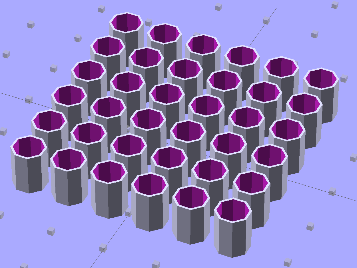
    These quilting pin caps are slightly longer than the previous version and, due to the M2’s smaller nozzle, have slightly thinner single-thread walls. Because Slic3r does a better (although not ideal) job of path planning than Skeinforge, it’s easier to create an array of the caps in the solid model than to manually add duplicates in Slic3r:

    Quilting Pin Cap - array
    Quilting Pin Cap – array

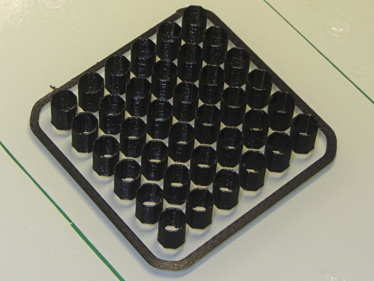
    They look like egg cases from Prometheus:

    Quilting pin cap array - on platform
    Quilting pin cap array – on platform

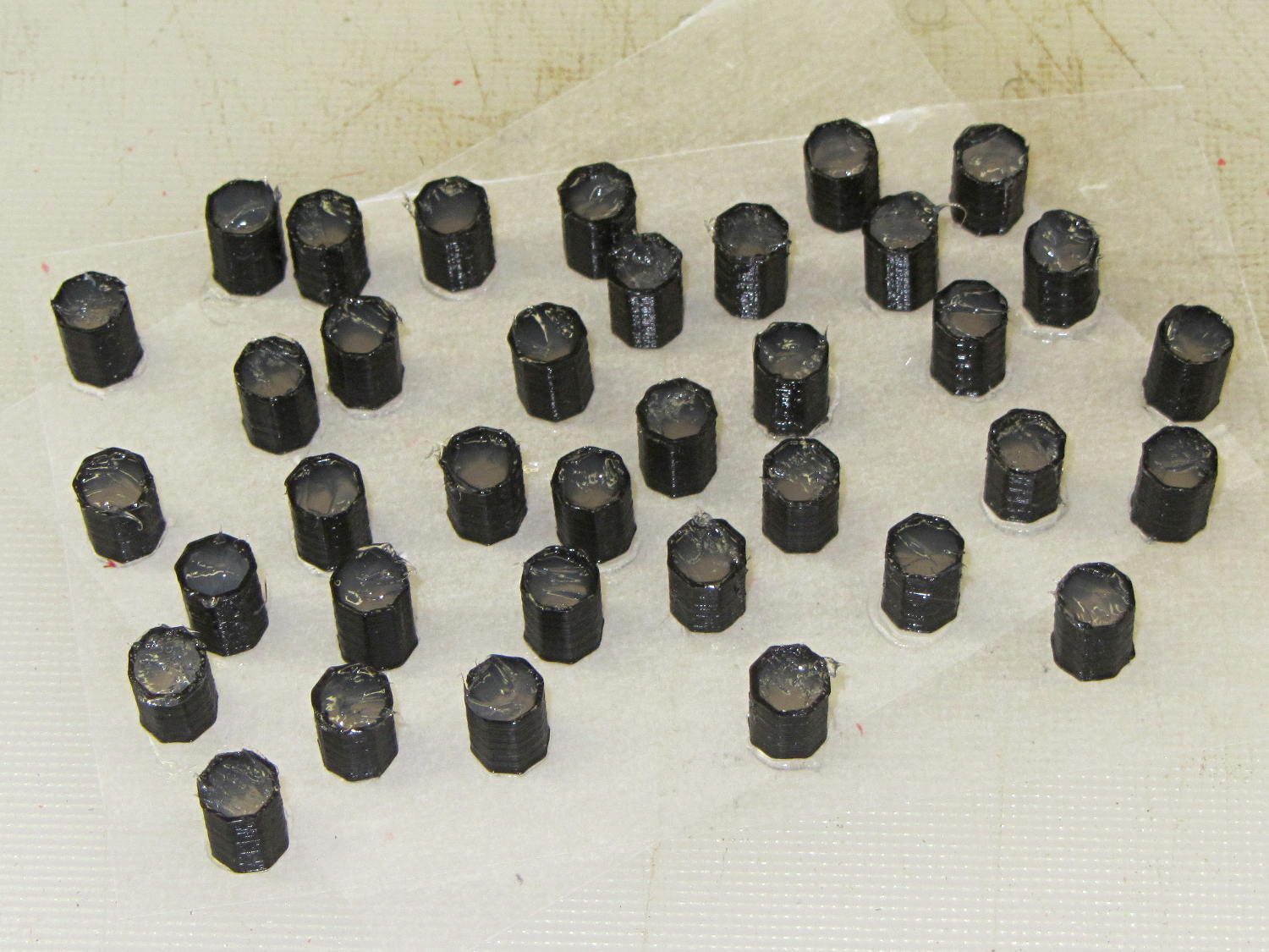
    Fill with silicone caulk on waxed paper and they look even more like that:

    Quilting pin caps - silicone fill
    Quilting pin caps – silicone fill

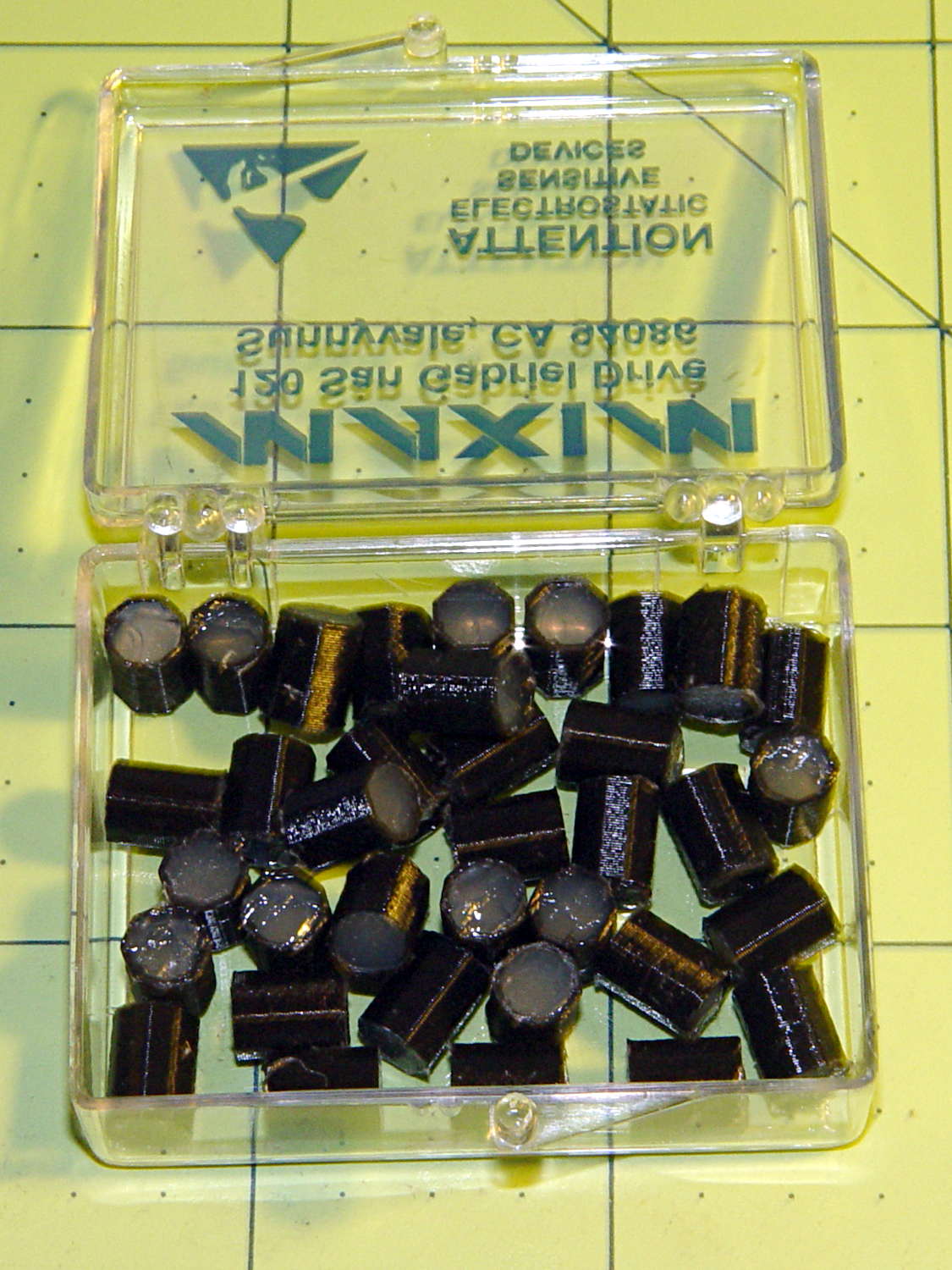
    Fast-forward a few days, rub off the excess caulk, trim off a few blobs, and they’re ready for presentation:

    Quilting pin caps - finished
    Quilting pin caps – finished

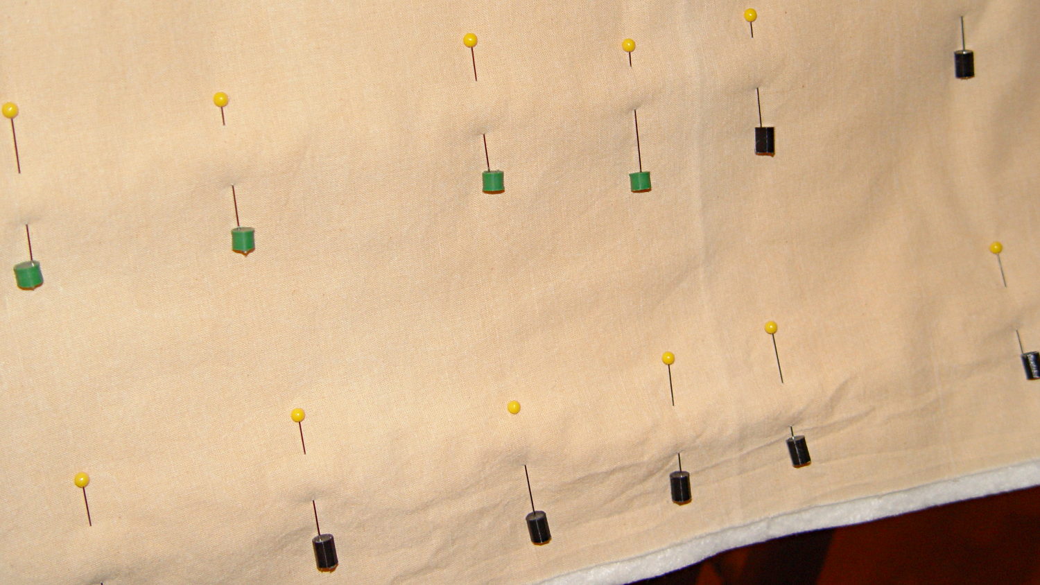
    In use, they look about like you’d expect:

    Quilting pin caps - in use
    Quilting pin caps – in use

    The pin caps I made from a 5 gallon bucket’s O-ring gasket didn’t work out well, as the plastic didn’t like being poked with pins and put up a stiff resistance. Silicone caulk has exactly the right consistency.

    When Mary ramps up a full-scale quilt, we’ll need a few hundred of the things. The commercial version has dropped to 40 cents each, which makes all this worthwhile.

    The OpenSCAD source code:

    // Quilting pin caps
    // Ed Nisley KE4ZNU April 2012
    //	January 2013 - modify for Slic3r and M2
    
    //- Extrusion parameters must match reality!
    //  Print with +1 shells and 3 solid layers
    
    ThreadThick = 0.20;
    ThreadWidth = 0.40;
    
    HoleWindage = 0.2;
    
    function IntegerMultiple(Size,Unit) = Unit * ceil(Size / Unit);
    
    Protrusion = 0.1;			// make holes end cleanly
    
    //----------------------
    // Dimensions
    
    ID = 5.0;
    OD = ID + 2*ThreadWidth;
    Length = 8.0;
    Sides = 8;
    
    CapArray = [6,6];			// XY layout of caps
    CapsOC = OD + 2.0;			// OC spacing
    
    //----------------------
    // Useful routines
    
    module PolyCyl(Dia,Height,ForceSides=0) {			// based on nophead's polyholes
    
      Sides = (ForceSides != 0) ? ForceSides : (ceil(Dia) + 2);
    
      FixDia = Dia / cos(180/Sides);
    
      cylinder(r=(FixDia + HoleWindage)/2,
               h=Height,
    	   $fn=Sides);
    }
    
    module ShowPegGrid(Space = 10.0,Size = 1.0) {
    
      RangeX = floor(100 / Space);
      RangeY = floor(125 / Space);
    
    	for (x=[-RangeX:RangeX])
    	  for (y=[-RangeY:RangeY])
    		translate([x*Space,y*Space,Size/2])
    		  %cube(Size,center=true);
    
    }
    
    module PinCap() {
    	rotate(180/Sides) {
    		difference() {
    		PolyCyl(OD,Length,8);
    		translate([0,0,-Protrusion])
    			PolyCyl(ID,(Length + 2*Protrusion),8);
    		}
    	}
    
    }
    
    //----------------------
    // Build them!
    
    ShowPegGrid();
    
    translate([(-CapsOC*(CapArray[0] - 1)/2),(-CapsOC*(CapArray[1] - 1)/2),0])
    	for (i=[0:(CapArray[0] - 1)],j=[0:(CapArray[1] - 1)])
    		translate([i*CapsOC,j*CapsOC,0])
    			PinCap();
    

    They seem to work pretty well…

  • Modified Quilting Foot: Speed Wrench Knob

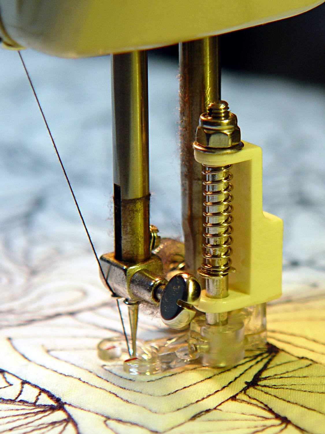
    The Nyloc nut atop that modified quilting foot requires more grip than fingers can provide:

    Modified Darning Foot - in action
    Modified Darning Foot – in action

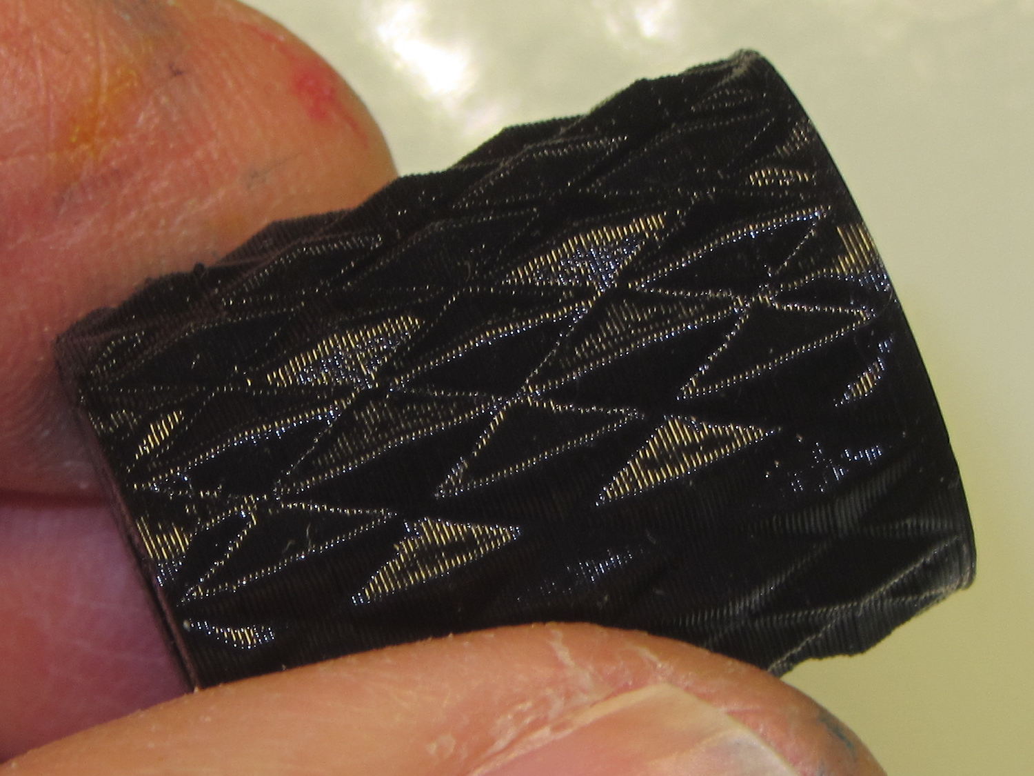
    The “precision” wrench I adapted to that nut works for small adjustments, but for larger ones it’s easier to take the foot off and spin this knob:

    Quilting Foot Knob - knurling
    Quilting Foot Knob – knurling

    It has a hex opening in each end that fits the nut, with a through hole for the bolt. The top looks exactly like you’d expect:

    Quilting Foot Knob - top
    Quilting Foot Knob – top

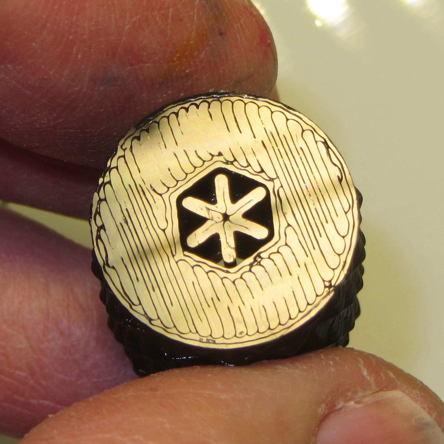
    The bottom needs a bit of support:

    Quilting Foot Knob - bottom support
    Quilting Foot Knob – bottom support

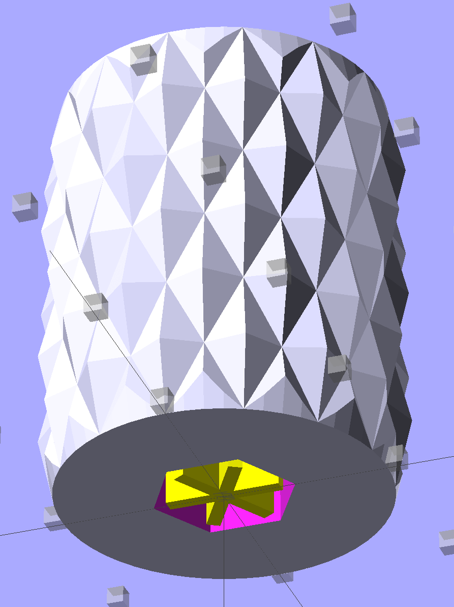
    The solid model shows off the support in color:

    Quilting Foot Knob
    Quilting Foot Knob

    The OpenSCAD source code doesn’t have many surprises:

    // Quilting foot knob
    // Ed Nisley KE4ZNU January 2013
    
    use <knurledFinishLib_v2.scad>
    
    //- Extrusion parameters must match reality!
    //  Print with +1 shells and 3 solid layers
    
    ThreadThick = 0.20;
    ThreadWidth = 0.40;
    
    HoleWindage = 0.2;
    
    function IntegerMultiple(Size,Unit) = Unit * ceil(Size / Unit);
    
    Protrusion = 0.1;			// make holes end cleanly
    
    //----------------------
    // Dimensions
    
    KnobOD = 20.0;
    KnobLength = 25.0;
    KnobSides = 12;
    
    DiamondLength = KnobLength/3;
    DiamondWidth = DiamondLength/2;
    DiamondDepth = 1.0;
    
    NutOD = 7.0;				// across flats!
    NutLength = 6.0;
    ScrewOD = 4.0;
    
    DoSupport = true;
    
    //----------------------
    // Useful routines
    
    module PolyCyl(Dia,Height,ForceSides=0) {			// based on nophead's polyholes
    
      Sides = (ForceSides != 0) ? ForceSides : (ceil(Dia) + 2);
    
      FixDia = Dia / cos(180/Sides);
    
      cylinder(r=(FixDia + HoleWindage)/2,
               h=Height,
    	   $fn=Sides);
    }
    
    module ShowPegGrid(Space = 10.0,Size = 1.0) {
    
      RangeX = floor(100 / Space);
      RangeY = floor(125 / Space);
    
    	for (x=[-RangeX:RangeX])
    	  for (y=[-RangeY:RangeY])
    		translate([x*Space,y*Space,Size/2])
    		  %cube(Size,center=true);
    
    }
    
    module Knob() {
    	rotate(180/Sides) {
    		difference() {
    //			cylinder(r=KnobOD/2,h=KnobLength,$fn=KnobSides);
    			render(convexity=10)
    			knurl(k_cyl_hg=KnobLength,
    				  k_cyl_od=KnobOD,
    				  knurl_wd=DiamondWidth,
    				  knurl_hg=DiamondLength,
    				  knurl_dp=DiamondDepth,
    				  e_smooth=DiamondLength/2);
    			translate([0,0,-Protrusion])
    				PolyCyl(ScrewOD,(KnobLength + 2*Protrusion),6);
    			translate([0,0,(KnobLength - NutLength)])
    				PolyCyl(NutOD,(NutLength + Protrusion),6);
    			translate([0,0,-Protrusion])
    				PolyCyl(NutOD,(NutLength + Protrusion),6);
    		}
    	}
    }
    
    module Support() {
    	color("Yellow")
    		for (Seg=[0:5]) {
    			rotate(360*Seg/6)
    			translate([0,0,(NutLength - ThreadThick)/2])
    				cube([(NutOD - 1*ThreadWidth),
    						2*ThreadWidth,
    						(NutLength - ThreadThick)],
    						center=true);
    			}
    }
    
    //----------------------
    // Build them!
    
    ShowPegGrid();
    
    Knob();
    
    if (DoSupport)
    	Support();
    

    Mary likes it… and thinks I’m being silly. She’s right, of course.

  • Rounded Rectangles in OpenSCAD: Mold Positives?

    A discussion on the OpenSCAD mailing list about making a rectangular solid with rounded edges having different radii eventually produced this delightful result:

    Basic Rounded Cube
    Basic Rounded Cube

    Those guys make me feel dumb, because they’re generally solving problems I can’t even imagine, but I know what to do with this solution. One could slice it in half horizontally, emboss a height map defining a logo / picture into the top surface, print it out on your favorite 3D printer, maybe smooth / seal the surface a bit, define it to be a positive mold pattern, cast / pour flexible silicone around it, and get a negative mold for a pourable precious material such as, oh, chocolate.

    You could make half a dozen of them, arrange them inside a suitable printed frame, pour the silicone, and get a multi-cavity mold for better manufacturing productivity.

    The overall block lacks draft, because the problem it solves presumes you need a block of specific outside dimensions: it overlays three full-size rectangular blocks that define the dimensions. OpenSCAD constructs spheres such that they may be slightly smaller than the defined radius at the poles and, depending on their alignment, a face at the equator may reduce the outer dimension of a surrounding hull.

    Given a sufficiently bendy silicone mold, you might not need any draft at all. If you do need draft and you don’t care about a very slightly undersized pattern, remove the internal blocks and increase the XY spacing of the lower four spheres by enough to make the draft come out right.

    The grayscale logo / image should have nice smooth transitions that produce suitable draft for the fine details; a bare black-and-white image might not work well. Shallow is good, but that conflicts with 3D printing’s crappy resolution: 1 mm = 10 layers, tops. That might not matter in practice.

    You’re supposed to temper the chocolate, but that’s probably more relevant for Fine Art molds.

    The (slightly modified) OpenSCAD source code:

    module rcube(size=[30, 20, 10], radius=[3, 2, 1], center=true)
    	hull() {
    		translate( center ? [0,0,0] : size/2 ) {
    			cube(size-2*radius+[2*radius[0],0,0],center=true);
    			cube(size-2*radius+[0,2*radius[1],0],center=true);
    			cube(size-2*radius+[0,0,2*radius[2]],center=true);
    
    			for(x = [-0.5,0.5], y = [-0.5,0.5], z = [-0.5,0.5])
    				translate([x * ( size[0] - 2*radius[0]),
    						   y * ( size[1] - 2*radius[1]),
    						   z * ( size[2] - 2*radius[2])])
    					scale([radius[0], radius[1], radius[2]])
    						sphere(1.0,$fn=4*4);
    		}
    	}
    
    rcube();
    

    When I get around to doing molds, maybe I can remember what I was thinking…

  • Canon NB-6LH Battery Test Fixture

    Our Larval Engineer’s new camera uses Canon NB-6LH batteries, which have exactly the same nominal capacity as the NB-5L batteries for my camera, despite being not quite the same size. I cannot imagine any reason for that, other than brand fractionation, but there it is.

    Fortunately, the sizes are pretty close, so I conjured up another 3D printed battery test fixture for the rundown tests:

    Canon NB-6L battery holder
    Canon NB-6L battery holder

    That hideous Powerpole thing came from one of the AA cell packs I’d been using to power the HTs on the bikes, before switching to lithium battery packs. It’s easier to harvest something suitable than to build a new thing, particularly for such a low duty cycle gadget.

    This view of the solid model shows the contact pins, with the lid floating over its alignment pegs (made from snippets of 1.75 mm filament):

    NB-6L Holder - fit layout
    NB-6L Holder – fit layout

    The pegs simplify gluing the lid in place, a process for which you can never have enough clamps:

    Canon NB-6L holder - lid gluing
    Canon NB-6L holder – lid gluing

    A cutaway shows the stepped holes around the contact pin, with the coil springs being the largest cylinder to the right of the solid-looking plug:

    NB-6L Holder - show layout
    NB-6L Holder – show layout

    The contact pins look like this, at least after one remembers to slide on all the parts before soldering the wires in place:

    Canon NB-6L holder - contact pin detail
    Canon NB-6L holder – contact pin detail

    I filed off the inevitable solder bumps, rounded the butt ends with gentle suasion, and generally tidied the pins up so they’re smooth and symmetrical. The springs don’t have a lot of oomph, so wasting any force on friction or binding is a Bad Thing.

    The holes require reaming with twist drills for a nice slip fit around the pins. The OpenSCAD script prints out the relevant diameters and depths:

    ECHO: "Contact pin tip dia: 1.6"
    ECHO: "Drill depth to taper end: 24.1 -- Dia: 2.4"
    ECHO: "            to ferrule end: 15 -- Dia: 3.1"
    ECHO: "            to plug end: 4 -- Dia: 5.2"
    

    Grab the proper drill in a pin punch, adjust so that length protrudes, and have at it. Making the holes about 0.2 mm larger than nominal works well, although your mileage will definitely vary.

    The build layout includes extra retaining plugs, as they tend to go walkabout under the bench:

    NB-6L Holder - build layout
    NB-6L Holder – build layout

    Add a dab of PVC cement with THF inside the holes and the plugs push firmly into place:

    Canon NB-6L holder - pin retaining plugs - detail
    Canon NB-6L holder – pin retaining plugs – detail

    I loves me my 3D printer…

    The OpenSCAD source code:

    // Holder for Canon NB-6L Li-Ion battery
    // Ed Nisley KE4ZNU January 2013
    
    include <MCAD/boxes.scad>
    
    // Layout options
    
    Layout = "Plugs";					//  Show Build Fit Case Lid Pins Plugs AlignPins
    
    //- Extrusion parameters - must match reality!
    //  Print with +2 shells and 3 solid layers
    
    ThreadThick = 0.20;
    ThreadWidth = 0.40;
    
    HoleWindage = 0.2;
    
    function IntegerMultiple(Size,Unit) = Unit * ceil(Size / Unit);
    
    Protrusion = 0.1;			// make holes end cleanly
    
    inch = 25.4;
    
    BuildOffset = 3.0;			// clearance for build layout
    
    Gap = 8.0;					// separation for Fit parts
    
    //- Battery dimensions - rationalized from several samples
    //  Coordinate origin at battery corner by contact plates on bottom surface
    
    BatteryLength = 42.5;
    BatteryWidth = 35.5;
    BatteryThick =  7.0;
    
    ContactWidth = 2.10;
    ContactLength = 4.10;
    ContactRecess = 0.85;
    
    ContactOC = 3.18;			// center-to-center across contact face
    ContactOffset = 4.45;		// offset from battery edge
    ContactHeight = 3.05;		// offset from battery bottom plane
    
    AlignThick = 2.8;			// alignment recesses on contact face
    AlignDepth = 2.0;			// into face
    AlignWidth1 = 0.7;			// across face at contacts
    AlignWidth2 = 2.0;			//  ... other edge
    
    //- Pin dimensions
    
    PinTipDia = 1.6;
    PinTipLength = 10.0;
    
    PinTaperLength = 2.3;
    
    PinShaftDia = 2.4;
    PinShaftLength = 6.8;
    
    PinFerruleDia = 3.1;
    PinFerruleLength = 2.0;
    
    PinLength = PinTipLength + PinTaperLength + PinShaftLength + PinFerruleLength;
    
    ExtendRelax = 1.5 + ContactRecess;		// pin extension when no battery is present
    ExtendOvertravel = 1.0;					//  ... beyond engaged position
    
    //- Spring dimensions
    
    SpringDia = 3.1;						// coil OD
    SpringMax = 9.3;
    SpringLength = SpringMax - 0.3;			// slightly compressed
    SpringMin = 4.5;
    
    SpringPlugOD = IntegerMultiple(5.0,ThreadWidth);		// plug retaining the spring
    SpringPlugID = 2.0;
    SpringPlugLength = IntegerMultiple(4.0,ThreadWidth);
    SpringPlugSides = 3*4;
    
    SpringTravel = ExtendRelax + ExtendOvertravel;
    
    //- Holder dimensions
    
    GuideRadius = ThreadWidth;						// friction fit ridges
    GuideOffset = 10;
    WallThick = 4*ThreadWidth;						// holder sidewalls
    
    BaseThick = 6*ThreadThick;			// bottom of holder to bottom of battery
    TopThick = 6*ThreadThick;			// top of battery to top of holder
    
    ThumbRadius = 10.0;			// thumb opening at end of battery
    
    CornerRadius = 3*ThreadThick;			// nice corner rounding
    
    CaseLength = SpringPlugLength + SpringLength + PinLength - ExtendRelax
    			+ BatteryLength + GuideRadius + WallThick;
    CaseWidth = 2*WallThick + 2*GuideRadius + BatteryWidth;
    CaseThick = BaseThick + BatteryThick + TopThick;
    
    AlignPinOD = 1.75;			// lid alignment pins - filament snippets
    AlignPinLength = 5.0;
    AlignPinInset = 7.0;
    
    //- XY origin at front left battery corner, Z on platform below that
    
    CaseLengthOffset = -(SpringPlugLength + SpringLength + PinLength - ExtendRelax);
    CaseWidthOffset = -(WallThick + GuideRadius);
    CaseThickOffset = BaseThick;
    
    LidLength = ExtendRelax - CaseLengthOffset;
    
    echo(str("Contact pin tip dia: ",PinTipDia));
    echo(str("Drill depth to taper end: ",
    		 (SpringPlugLength + SpringLength + PinFerruleLength + PinShaftLength + PinTaperLength),
    		 " -- Dia: ",PinShaftDia));
    echo(str("            to ferrule end: ",
    		  (SpringPlugLength + SpringLength + PinFerruleLength),
    		 " -- Dia: ",PinFerruleDia));
    echo(str("            to plug end: ",SpringPlugLength,
    		 " -- Dia: ",SpringPlugOD));
    
    //----------------------
    // Useful routines
    
    module PolyCyl(Dia,Height,ForceSides=0) {			// based on nophead's polyholes
    
      Sides = (ForceSides != 0) ? ForceSides : (ceil(Dia) + 2);
    
      FixDia = Dia / cos(180/Sides);
    
      cylinder(r=(FixDia + HoleWindage)/2,
               h=Height,
    	   $fn=Sides);
    }
    
    module ShowPegGrid(Space = 10.0,Size = 1.0) {
    
      Range = floor(50 / Space);
    
    	for (x=[-Range:Range])
    	  for (y=[-Range:Range])
    		translate([x*Space,y*Space,Size/2])
    		  %cube(Size,center=true);
    
    }
    
    //-------------------
    
    //-- Guides for tighter friction fit
    
    module Guides() {
      	  translate([GuideOffset,-GuideRadius,CaseThickOffset])
    		PolyCyl(2*GuideRadius,(BatteryThick - Protrusion),4);
    	  translate([GuideOffset,(BatteryWidth + GuideRadius),CaseThickOffset])
    		PolyCyl(2*GuideRadius,(BatteryThick - Protrusion),4);
    	  translate([(BatteryLength - GuideOffset),-GuideRadius,CaseThickOffset])
    		PolyCyl(2*GuideRadius,(BatteryThick - Protrusion),4);
    	  translate([(BatteryLength - GuideOffset),(BatteryWidth + GuideRadius),CaseThickOffset])
    		PolyCyl(2*GuideRadius,(BatteryThick - Protrusion),4);
    	  translate([(BatteryLength + GuideRadius),GuideOffset/2,CaseThickOffset])
    		PolyCyl(2*GuideRadius,(BatteryThick - Protrusion),4);
    	  translate([(BatteryLength + GuideRadius),(BatteryWidth - GuideOffset/2),CaseThickOffset])
    		PolyCyl(2*GuideRadius,(BatteryThick - Protrusion),4);
    
    }
    
    //-- Contact pins (holes therefore)
    
    module PinShape() {
    
      union() {
    	cylinder(r=(PinTipDia + HoleWindage)/2,h=(PinTipLength + Protrusion),$fn=6);
    
    	translate([0,0,PinTipLength])
    	  cylinder(r=(PinShaftDia + HoleWindage)/2,
    			   h=(PinTaperLength + PinShaftLength + Protrusion),$fn=6);
    
    	translate([0,0,(PinLength - PinFerruleLength)])
    	  cylinder(r=(PinFerruleDia + HoleWindage)/2,
    				h=(PinFerruleLength + Protrusion),$fn=6);
    
    	translate([0,0,(PinLength)])
    	  cylinder(r=(SpringDia + HoleWindage)/2,
    				h=(SpringLength + Protrusion),$fn=6);
    
    	translate([0,0,(PinLength + SpringLength - HoleWindage)])	// windage for hole length
    	  cylinder(r=(SpringPlugOD + HoleWindage)/2,h=3*SpringPlugLength,$fn=SpringPlugSides);
    
    //	  translate([0,0,(PinLength + SpringLength + SpringPlugLength)])
    //	  cylinder(r=(SpringPlugOD + HoleWindage)/2,h=2*SpringPlugLength,$fn=SpringPlugSides);	// extend hole
      }
    
    }
    
    module PinAssembly() {
    
      translate([ExtendRelax,ContactOffset,CaseThickOffset + ContactHeight]) {
    	rotate([0,270,0]) {
    	  PinShape();												// pins
    	  translate([0,(2*ContactOC),0])
    		PinShape();
    	}
      }
    
    }
    
    //-- Alignment pins
    
    module AlignPins() {
    
    	for (x=[-1,1])
    		translate([x*(LidLength - 2*AlignPinInset)/2,0,0])
    			rotate(45)
    			PolyCyl(AlignPinOD,AlignPinLength);
    }
    
    //-- Case with origin at battery corner
    
    module Case() {
    
      difference() {
    
    	union() {
    
    	  difference() {
    		translate([(CaseLength/2 + CaseLengthOffset),
    				  (CaseWidth/2 + CaseWidthOffset),
    				  (CaseThick/2)])
    		  roundedBox([CaseLength,CaseWidth,CaseThick],CornerRadius); 	// basic case shape
    
    		translate([-ExtendOvertravel,-GuideRadius,CaseThickOffset])
    		  cube([(BatteryLength + GuideRadius + ExtendOvertravel),
    				(BatteryWidth + 2* GuideRadius),
    				(BatteryThick + Protrusion)]);						// battery space
    
    	  }
    
    	  Guides();
    
    	  translate([-ExtendOvertravel,-GuideRadius,BaseThick])
    		cube([(AlignDepth + ExtendOvertravel),
    			  (AlignWidth1 + GuideRadius),
    			  AlignThick]);											// alignment blocks
    	  translate([-ExtendOvertravel,
    				 (BatteryWidth - AlignWidth2),
    				 BaseThick])
    		cube([(AlignDepth + ExtendOvertravel),
    			  (AlignWidth2 + GuideRadius),
    			  AlignThick]);
    
    	}
    
    	translate([(-ExtendOvertravel),
    			   (CaseWidthOffset - Protrusion),
    			   (CaseThickOffset + BatteryThick)])
    	  cube([CaseLength,
    		    (CaseWidth + 2*Protrusion),
    		    (TopThick + Protrusion)]);								// battery access
    
    	translate([(CaseLengthOffset - Protrusion),
    			   (CaseWidthOffset - Protrusion),
    			   (CaseThickOffset + BatteryThick)])
    	  cube([(CaseLength + 2*Protrusion),
    		    (CaseWidth + 2*Protrusion),
    		    (TopThick + Protrusion)]);								// battery insertion allowance
    
    	translate([(BatteryLength - Protrusion),
    			    (CaseWidth/2 + CaseWidthOffset),
    			    (CaseThickOffset + ThumbRadius)])
    	  rotate([90,0,0])
    		rotate([0,90,0])
    		  cylinder(r=ThumbRadius,
    				   h=(WallThick + GuideRadius + 2*Protrusion),
    				   $fn=22);											// remove thumb notch
    
    	PinAssembly();
    
    	translate([-LidLength/2,BatteryWidth/2,CaseThick - TopThick - (AlignPinLength - TopThick/2)])
    		AlignPins();
      }
    
    }
    
    module Lid() {
    
      difference() {
    	translate([0,0,(CaseThick/2 - BaseThick - BatteryThick)])
    	  roundedBox([LidLength,
    				 CaseWidth,CaseThick],CornerRadius);
    
    	translate([0,0,-(CaseThick/2)])
    	  cube([(LidLength + 2*Protrusion),
    		    (CaseWidth + 2*Protrusion),
    		    (CaseThick)],center=true);
    
    	translate([-ExtendRelax,0,-(AlignPinLength - TopThick/2)])
    		AlignPins();
      }
    
    }
    
    module PlugShape() {
    
      difference() {
    	cylinder(r=SpringPlugOD/2,h=SpringPlugLength,$fn=SpringPlugSides);
    	translate([0,0,-Protrusion])
    	  PolyCyl(SpringPlugID,(SpringPlugLength + 2*Protrusion),SpringPlugSides);
      }
    }
    
    module Plugs() {
      translate([0,ContactOC,0])
    	PlugShape();
      translate([0,-ContactOC,0])
    	PlugShape();
    }
    
    //-------------------
    // Build it!
    
    ShowPegGrid();
    
    if (Layout == "Case")
      Case();
    
    if (Layout == "Lid")
      Lid();
    
    if (Layout == "Plugs")
    	for (i=[-1:1])
    		translate([i*1.5*SpringPlugOD,0,0])
    			Plugs();
    
    if (Layout == "Pins")
      PinShape();
    
    if (Layout == "AlignPins")
      AlignPins();
    
    if (Layout == "Show") {								// reveal pin assembly
      difference() {
    	Case();
    
    	translate([(CaseLengthOffset - Protrusion),
    			   (CaseWidthOffset - Protrusion + WallThick + ContactOffset + ContactOC),
    			   (BaseThick + ContactHeight)])
    	  cube([(-CaseLengthOffset + Protrusion),
    			 (CaseWidth + 2*Protrusion),
    			 CaseThick + BaseThick - ContactHeight + Protrusion]);
    
    	translate([(CaseLengthOffset - Protrusion),
    			   (CaseWidthOffset - Protrusion),
    			   -Protrusion])
    	  cube([(-CaseLengthOffset + Protrusion),
    			 (WallThick + GuideRadius + ContactOffset + Protrusion),
    			 CaseThick]);
      }
    
      translate([ExtendRelax,ContactOffset,(CaseThickOffset + ContactHeight)]) {	// pins
    	rotate([0,270,0]) {
    	  %PinShape();
    //	  translate([0,(2*ContactOC),0])
    //		%PinShape();
    	}
      }
    
      translate([CaseLengthOffset,ContactOffset,(CaseThickOffset + ContactHeight)])
    	rotate([0,90,0])
    	  PlugShape();
    }
    
    if (Layout == "Build") {
      translate([-(CaseLength/2 + CaseLengthOffset),-(CaseWidthOffset - BuildOffset),0])
    	Case();
      translate([CaseWidth/2,(CaseLengthOffset/2 - BuildOffset),0])
    	rotate([0,0,90])
    	  Lid();
      for (i=[-1:1])
    	translate([CaseLengthOffset/2 + i*1.5*SpringPlugOD,-CaseWidth/2,0])
    		Plugs();
    }
    
    if (Layout == "Fit") {
      Case();
      translate([(-LidLength/2 + ExtendRelax),
    			(CaseWidth/2 + CaseWidthOffset),
    			(BaseThick + BatteryThick + Gap)])
    	  Lid();
      translate([ExtendRelax,ContactOffset,CaseThickOffset + ContactHeight]) {	// pins
    	rotate([0,270,0]) {
    	  %PinShape();
    	  translate([0,(2*ContactOC),0])
    		%PinShape();
    	}
      }
    
      translate([CaseLengthOffset,
    			(ContactOffset + ContactOC),
    			(CaseThickOffset + ContactHeight)])
      rotate([0,90,0])
    	Plugs();
    
      translate([-LidLength/2,BatteryWidth/2,CaseThick])
    #	AlignPins();
    
    }
    
    
  • Thing-o-Matic 286 Conversion

    A few months ago I fired the Thing-O-Matic, only to have it wake up dead. Not exactly dead, but spitting out checksum errors on simple G-Code files sent from Pronterface, which used to work just fine. Trying a bit of this-and-that to no avail, I proposed to The Mighty Thor that I could loan the carcass to Squidwrench, reanimate it with a less bizarre set of hardware and firmware than the much-hacked Makerbot menagerie under the hood, and use it as an exemplar in my 3D Printing classes.

    Fortunately, that particular Thing-O-Matic has the most well-documented hardware evah

    Matt suggested an Azteeg X3 controller, because it has thermocouple inputs that match the existing sensor, Thor ordered one, and I tinkered up a first-pass version of Marlin that could read the inputs and twiddle the motors. The firmware is on Github, not that you’ll need it for anything you’re doing; more on that later.

    Here’s the Official Doc for the microstepping jumpers hidden under the driver boards:

    Azteeg X3 - microstep jumpers
    Azteeg X3 – microstep jumpers

    That’s XYZE = 16 16 8 4, respectively, with a spare slot (and spare driver, not installed) for the second extruder it’ll never have.

    A first pass at setting the motor currents

    The extruder’s Type K thermocouple connects to the TC1 port on the shield, exactly reversed from the way you see the test thermocouple there: the red lead is to the left, the yellow lead is to the right. If you get it backwards, the indicated temperature goes down when you touch the bead. The printer’s thermocouple has some backstory.

    The 10 kΩ thermistor bead connects to the BED port on the main board and isn’t polarized. The Heated Build Platform has a bit of backstory, too.

    The gutted TOM286 carcass with the MBI hardware off to the side:

    TOM286 - gutted electronics bay
    TOM286 – gutted electronics bay

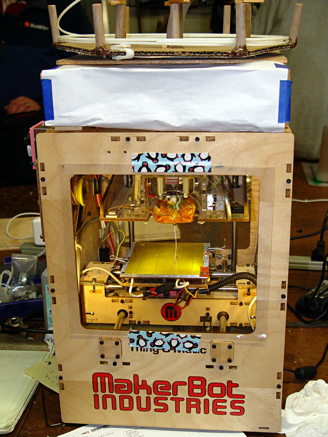
    After a few sessions, it looked pretty cheerful again:

    TOM286 - reborn at Squidwrench
    TOM286 – reborn at Squidwrench

    The penguin duct tape adds a festive flair, don’t you agree?

    This is what you see when looking down through the acrylic baseplate:

    Azteeg X3 - inside TOM286
    Azteeg X3 – inside TOM286

    The blurry silver rectangle off to the left is an aluminum channel glommed to bottom of the acrylic baseplate with silicone snot to eliminate a nasty mechanical resonance.

    The thermal cutout circuitry isn’t wired in yet; the ATX power supply has its -Power-On pin hotwired to the adjacent ground pin for now. The X3 gets its power directly from the +12 V supply, so there doesn’t seem to be any way to power the X3 from the +5 V Standby ouput, deliver +12 V to the motors, and switch the supply through the X3’s ATX output pin.

    The heaters work fine, the motors turn properly, and the extruder feeds molten plastic; all the motor calibrations seem to be pretty close. The first test object was a total botch, of course, but the printer’s parts seem to work OK again.

    Next step: calibration!

  • Water Cooled Stepper Motors: Flow Calculation

    A discussion on the Makergear Google Group about a heated enclosure prompted me to run the numbers for cooling stepper motors with water, rather than fans and finned heatsinks.

    The general idea comes from my measurements of the air-cooled heatsink stuck to a stepper’s end cap. The metal-to-metal conductivity works surprisingly well and reduces the case temperature to slightly over ambient with decent airflow through the heatsink; epoxying a cold plate to the end cap should work just as well. A NEMA 17 stepper case is 42.3 mm square, so a standard 40 mm square CPU cooling plate will fit almost exactly.

    The question then becomes: how much water flow do you need to keep the motors cool?

    Some numbers:

    • Water’s heat capacity is 4.2 J/g·K
    • 1 J = 1 W·s, 1 W = 1 J/s
    • NEMA 17 motors dissipate about 5 W (13 W if you’re abusing them)
    • We’ll cool all four motors in parallel, for a total of 20 W
    • Allow a 5 K = 5 °C temperature rise in each cold plate

    Rub them all together:

    (20 J/s) / (5 K * (4.2 J/g·K)) = 0.95 g/s

    For water, 1 g = 1 cc, so the total flow is 1 cc/s = 3600 cc/h = 3.6 liter/h, which, here in the US, works out to a scant 1 gallon/hour. It’s tough getting a pump that small and cheap flowmeters run around 0.5 liter/m…

    If you don’t want a pump. put an aquarium up on a (sturdy) shelf and drain it through the cold plates. A cubic foot of water, all eight gallons and sixty-some-odd pounds of it, will last 8 hours, which should be enough for most printing projects.

    If you want reliability, drain the coolers into a sump with a float switch (high = on), put another float switch (high = off) on the aquarium, and have the pump top up the aquarium. If the pump fails, your steppers stay cool for the next 8 hours. Heating the water about 5 °C during 8 hours won’t require active cooling.

    Now, managing the hoses leading to the X axis stepper may be challenging, but a cable drag chain would control the rest of the wiring, too.