Ed Nisley's Blog: Shop notes, electronics, firmware, machinery, 3D printing, laser cuttery, and curiosities. Contents: 100% human thinking, 0% AI slop.
Having discovering that the chocolate mold positives suffered from sparse top infill, to the extent that silicone rubber would flow right though the surface…
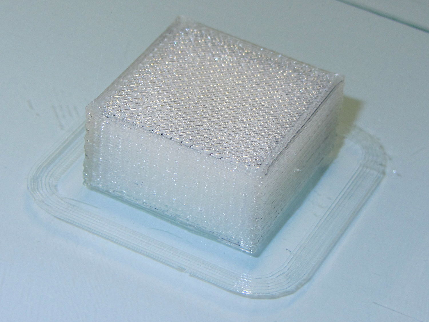
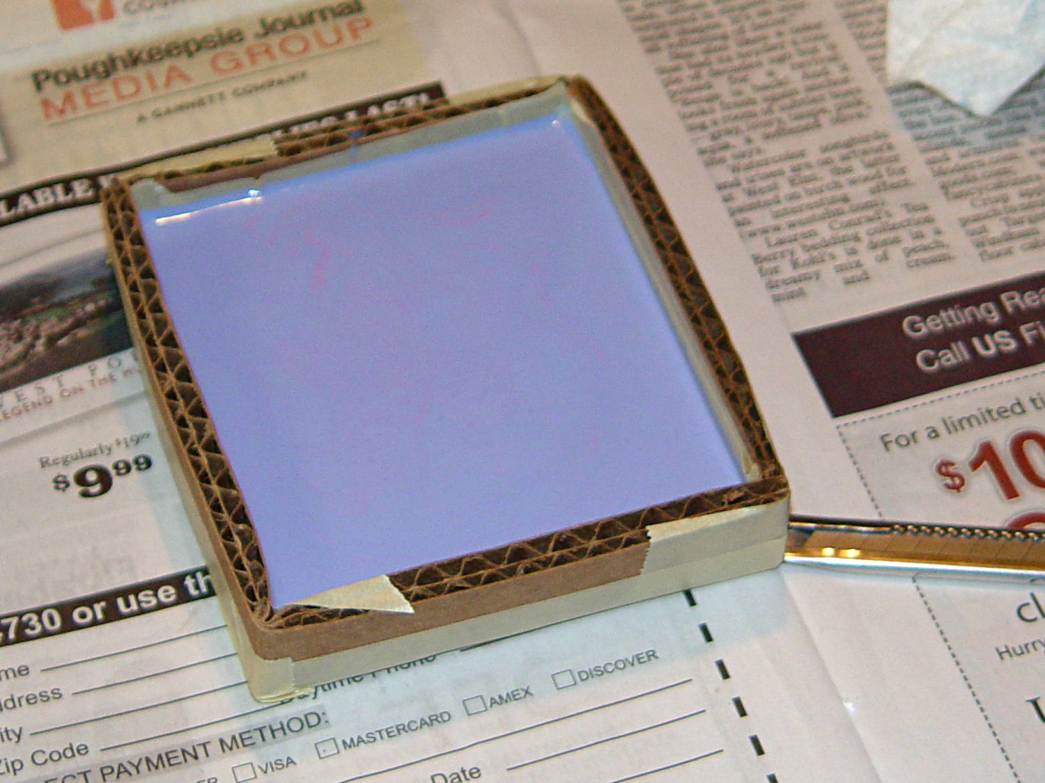
Not only were the infilled surfaces porous, I could see right through the block! That’s impossible to photograph, but here’s a laser beam shining through the entire 10 mm stack, showing how precisely the M2 aligns 50 under-filled thread layers:
Solid cube – laser transmission
The yellow spot in the middle marks the overexposed laser beam. There’s a distinct beam passing through the block that, with the proper orientation, can create a spot on the cutting mat atop my desk.
In fact, I can blow air through the blocks; one could use them as (rather coarse) air filters.
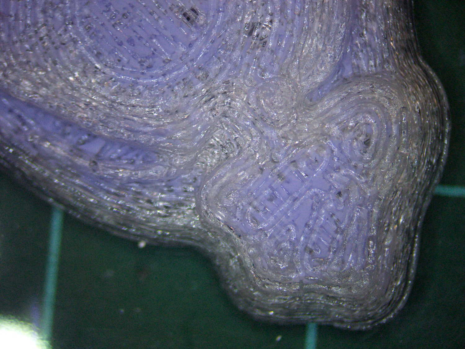
Normally, underfill happens when a mechanical problem prevents the printer from feeding enough filament to keep up with demand, but that’s not the case here: the perimeter threads came out exactly 0.4 mm wide for the entire height of the cube, as you can see if you click the picture for more dots. The top and bottom infill, plus all the interior threads, seem to be about half the nominal width and don’t touch their neighbors on the same XY plane at all.
The colors show the length of extruder filament per millimeter of XY motion, not the usual XY speed, with the two perimeter threads at 0.033 mm/mm and the interior at 0.18 mm/mm. In round numbers, the G-Code starves the infill by a factor of 1.8, which is close enough to the factor of two I’d guessed going into this mess.
Being that type of guy, I set the exact extrusion thickness and width (0.20 x 0.40 mm), rather than let Slic3r pick them. The extruded thread has a fixed cross-section of (roughly) 0.080 mm2 and a millimeter of XY motion thus requires 0.080 mm3 of filament.
The PLA filament measures 1.79 mm diameter, for a cross-section of 2.5 mm2. Getting 0.080 mm3 from the incoming filament requires feeding 0.032 mm into the extruder, which is almost exactly what you see for the perimeter threads.
After restoring Slic3r’s default configuration, the problem Went Away, which suggests that I backed the algorithms into a corner with some perverse combination of settings. Rebuilding my usual configuration from the defaults also worked fine, so it’s obviously not Slic3r’s problem.
Which one is not like the other ones?
Solid cube tests
You can see the thin infill on three of those cubes, with the solid one in the lower right showing how it should look.
The solid cube weighs 4.4 g and the thin-fill variations weigh 2.7 to 2.9 g. Assuming PLA density = 1.25 g/cm3 and “cube” volume = 4 cm3, a completely solid cube should weigh 5.0 g. I think 4.4 g is close enough; the top surface came out flat with nice adjacent-thread fusion. Working backwards, the average fill = 88%; the perimeter is fused-glass solid, so the actual infill will be a bit under that.
I generally run Slic3r from my desktop box, with ~/.Slic3r symlinked to the actual config directory and its files on the NFS server downstairs. Perhaps running different versions of Slic3r on two or three different boxes, all using the same config files, wrecked something that didn’t show up in the UI and produced bad slices. I probably ran two different versions of Slic3r at the same time against the same files, although I wasn’t simultaneously typing at both keyboards.
Moral of the story: check the G-Code before assuming a hardware failure!
The latter, of course: I blundered the inner corner radius, which occasionally produced little tiny dots of infill that shouldn’t be there. Just one of those errors that hides in plain sight until something else goes wrong, then it’s obvious.
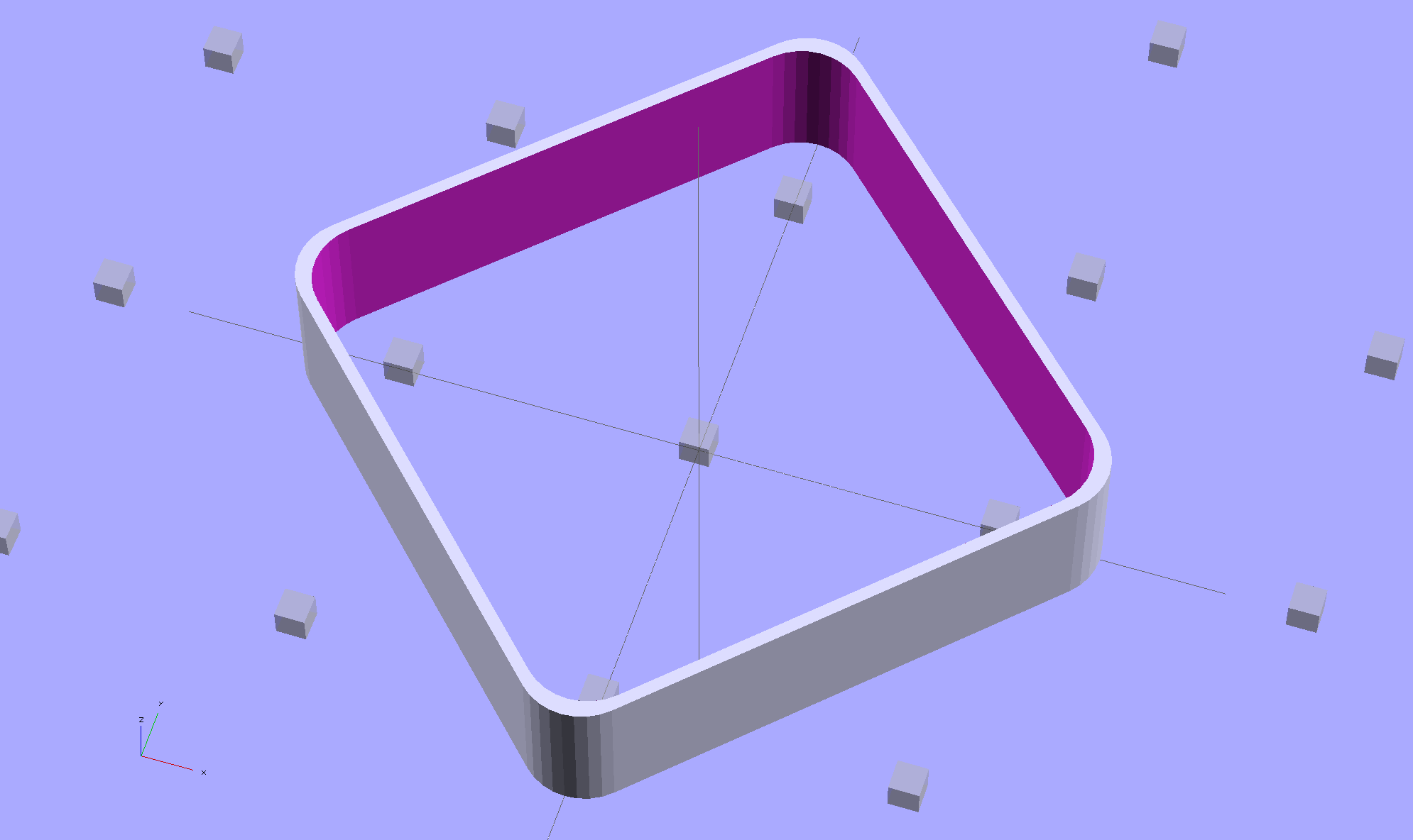
Rather than fix the Minkowski version, I rebuilt it using the hull() operator to shrinkwrap four cylinders for each solid, then remove the smaller block from the larger. Commenting out the hull() operators shows that the cylinders now line up properly:
Thinwall Open Box – un-hulled – solid model
The OpenSCAD source code:
// Thin wall open box calibration piece
// Adapted from Coasterman's Calibration set
// Ed Nisley - KE4ZNU - Dec 2011
// Adjust for Slic3r/M2 - March 2013
// Reworked for hull() with correct corner radii - April 2014

//-------
//- Extrusion parameters must match reality!
//  None of the fill parameters matter

ThreadThick = 0.20;
ThreadWidth = 0.40;

Protrusion = 0.1;           // make holes end cleanly

function IntegerMultiple(Size,Unit) = Unit * ceil(Size / Unit);

//-------
// Dimensions

Height = IntegerMultiple(5.0,ThreadThick);

WallThick = ThreadWidth;

CornerRadius = 2.0;
CornerSides = 4*8;

SideLen = 20.0 - 2*CornerRadius;

Rotation = 45;

//-------

module ShowPegGrid(Space = 10.0,Size = 1.0) {

  Range = floor(50 / Space);

    for (x=[-Range:Range])
      for (y=[-Range:Range])
        translate([x*Space,y*Space,Size/2])
          %cube(Size,center=true);
}

//-------

ShowPegGrid();

rotate(Rotation)
	difference() {
		hull() {
			for (i=[-1,1], j=[-1,1])
				translate([i*SideLen/2,j*SideLen/2,0])
					cylinder(r=CornerRadius,h=Height,$fn=CornerSides);
		}
		hull() {
			for (i=[-1,1], j=[-1,1])
				translate([i*SideLen/2,j*SideLen/2,-Protrusion])
					cylinder(r=(CornerRadius - WallThick),h=(Height + 2*Protrusion),$fn=CornerSides);
		}
	}
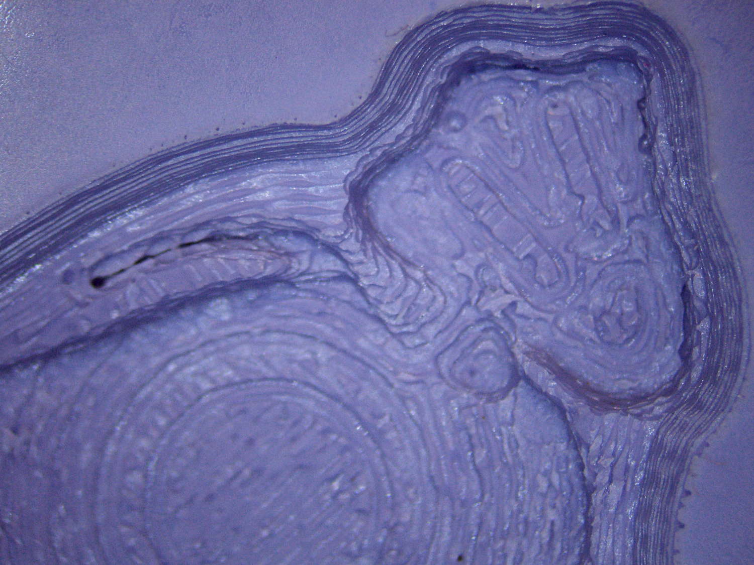
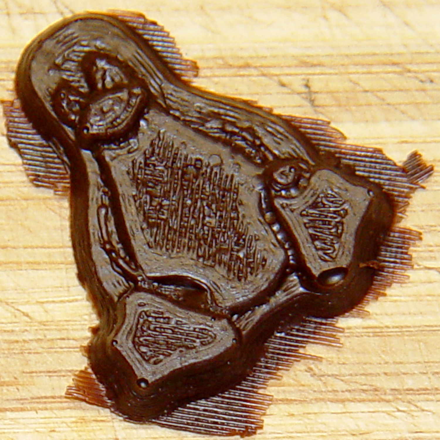
The PLA positive, after removing the silicone negative, showing the silicone below the surface:
Tux Gradient – PLA positive detail
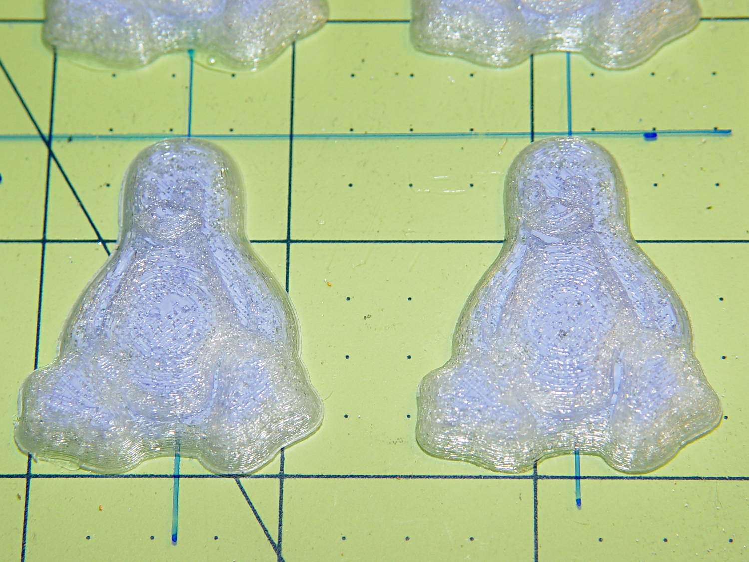
The corresponding silicone negative cavity, flipped top-to-bottom:
Tux Gradient – silicone negative detail
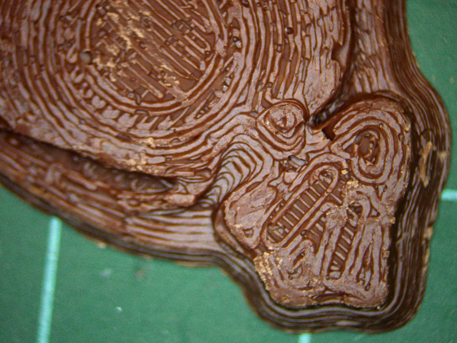
The milk chocolate result, although probably not from the same cavity:
Tux Gradient – milk chocolate detail
The radial gradient on the tummy comes through clearly and, I think, pleasingly, even though it’s only a few layers tall. The threads defining the flipper just above (to the left, in these images) of the foot show where the flipper crosses the tummy and foot level. I didn’t expect the foot webbing grooves to get that ladder-like texture, but I suppose having non-slip foot treads would be an advantage.
If you don’t mind the hand-knitted texture, which I don’t, this process seems perfectly workable.
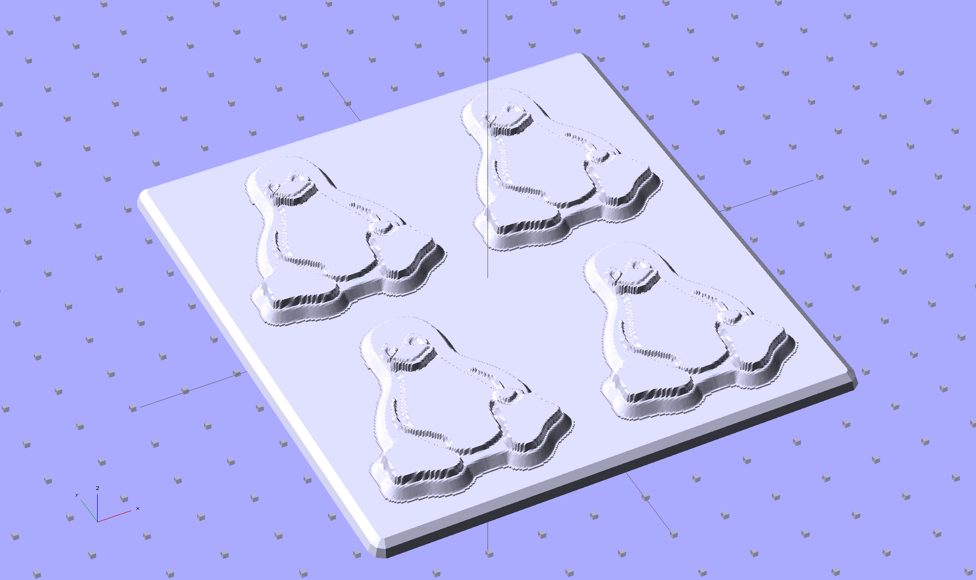
Although directly printing the 2×2 molds worked reasonably well, that does not scale to larger arrays, because OpenSCAD doesn’t handle the profusion of vertices with any grace. Duplicating the STL file created from the height map image, however, isn’t a problem:
Tux-Gradient – Slic3r layout
I actually did it in two passes: 4 molds to be sure they’d come out right, then another dozen. Figure a bit under two hours for the lot of them, no matter how you, ah, slice it.
A grid drawn directly on 1/16 inch = 1.5 mm acrylic sheet guided the layout:
Tux Gradient 4×4 – mold as-cast
I anointed the back of each mold positive with PVC pipe cement, the version with tetrahydrofuran to attack the PLA and acetone/MEK to attack the acrylic, lined it up, and pressed it in place. The positives have recesses for alignment pins, but even I think that’s overkill in this application.
Memo to Self: Flip the acrylic over before gluing, so the guide lines wipe neatly off the bottom.
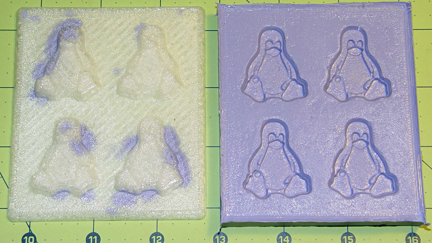
Tape a cardboard frame around the acrylic, mix & pour the silicone, put it on the floor to ensure it’s level (unlike our kitchen table), wait overnight for the cure, then peel positive and negative apart:
Tux Gradient 4×4 – mold separated
As before, the top surface of the positives isn’t watertight, so the silicone flowed through into the molds. This isn’t a simple extruder calibration issue, because the thinwall boxes are spot on, all the exterior dimensions are accurate, and everything else seems OK. What’s not OK is that threads on the top and (now that I look at it) bottom surfaces aren’t properly joining.
A closeup of the positive shows silicone between the threads and under the surface:
Tux Gradient 4×4 – postive detail
But the negative silicone looks just fine, in the usual hand-knitted way of all 3D printed parts:
Tux Gradient 4×4 – negative detail
Definitely fewer bubbles than before, although the flange between the flippers (wings? whatever) and the body isn’t as clean as it could be. Doing better may require pulling a vacuum on the silicone, which would mean the positives really must be air-tight solids.
Anyhow, the acrylic base produced a wonderfully flat surface that should make it a lot easier to run a scraper across the chocolate to remove the excess. Not that excess chocolate is ever a problem, but it’s the principle of the thing.
This is the simple height-map Tux image I’d been using for the chocolate molds:
Tux_Hi_Profile
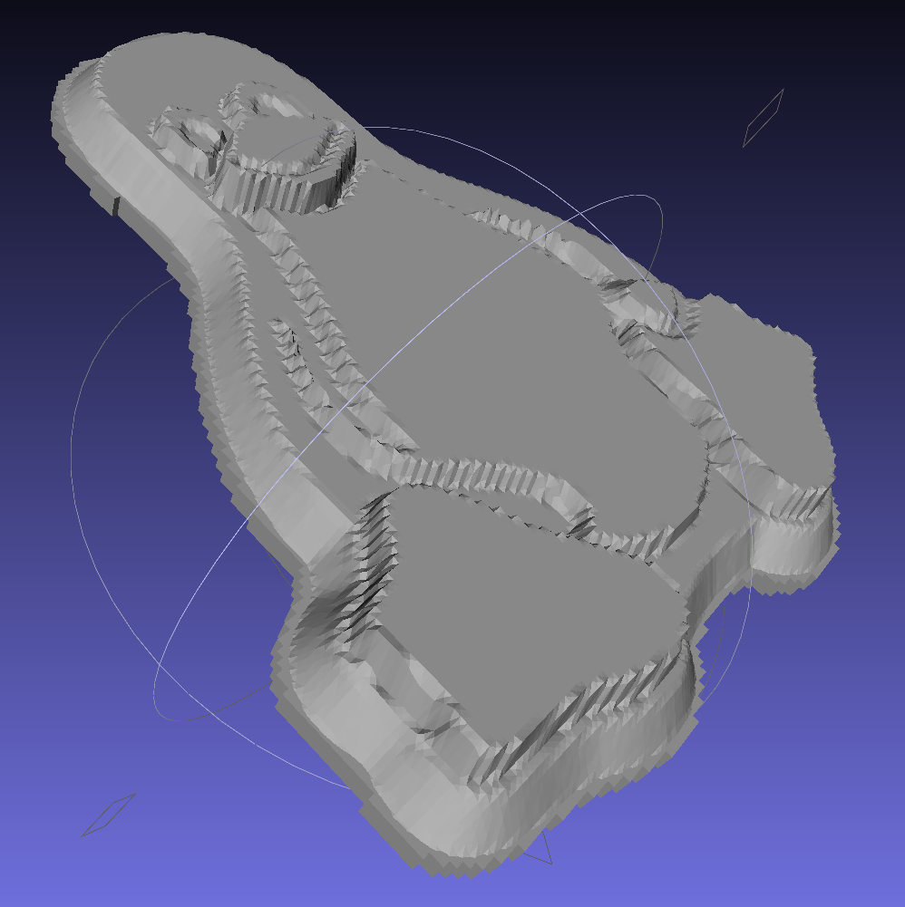
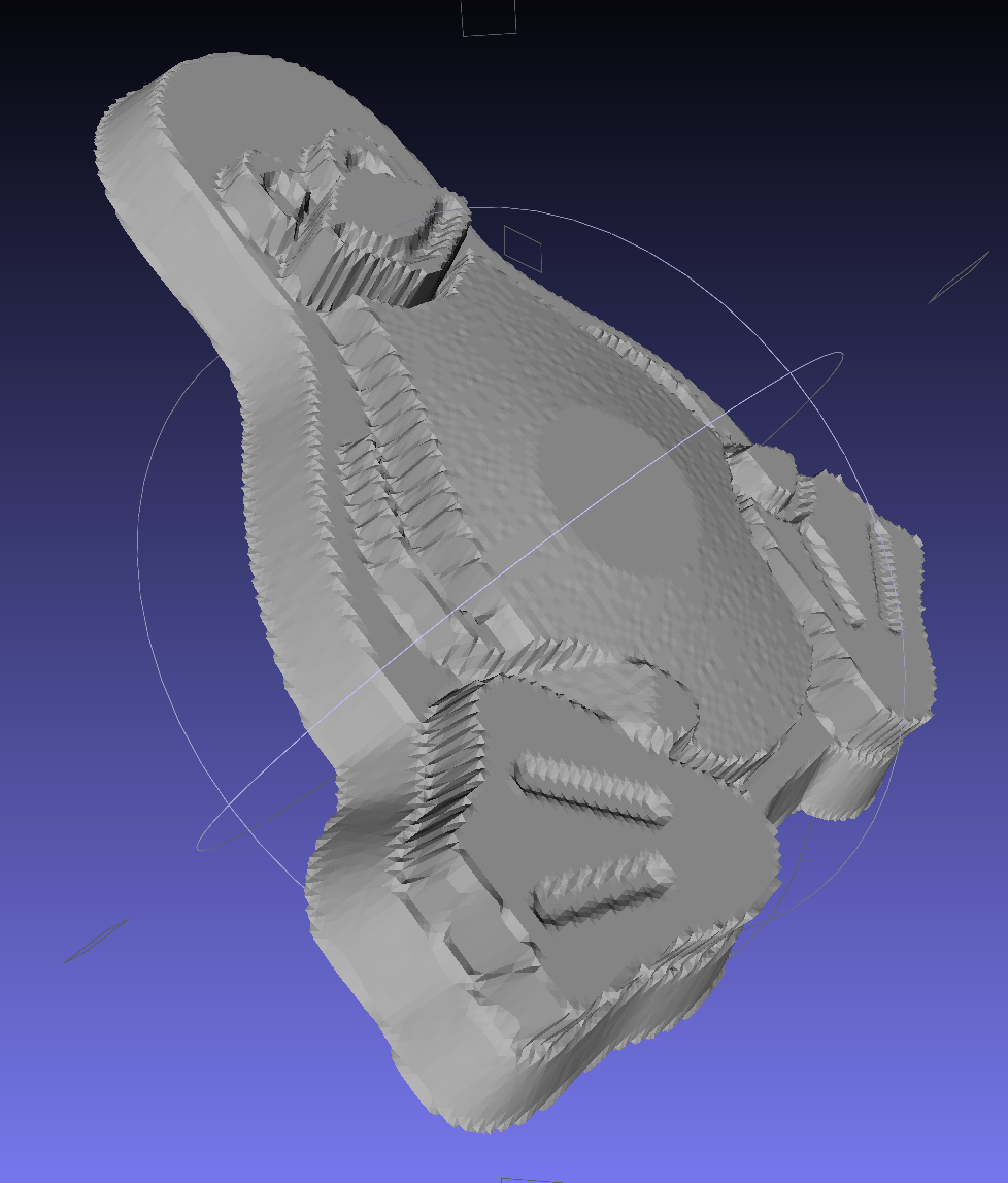
But the poor critter looks a bit flattened:
Tux_Hi_Profile – solid model
The final result is tastier, but gives off a roadkill vibe:
Tux chocolates – detail
After a few tweaks to the image, now he has a radial gradient on his tummy, his right flipper extends forward, his feet have webs, and his smile looks radiant. The gray levels now extend over a larger range with a bit more separation, with the intent that he’ll now be 5 mm thick:
A rough estimate of the volume and measurement thereof:
Assume 1 cm slab thickness for mold cavities 4 or 5 mm deep
Measure size of base plate in cm (given by OpenSCAD script in mm)
Compute slab volume in cubic cm = millliliters (ignoring mold cavity volumes)
Divide by 2 to find volume of each silicone component
Mark that volume on the side of two sacrificial containers
Pour silicone components into those containers
Pour one into the other, mix twice as long as you think you should
Scrupulously avoid cross-contaminating the original containers!
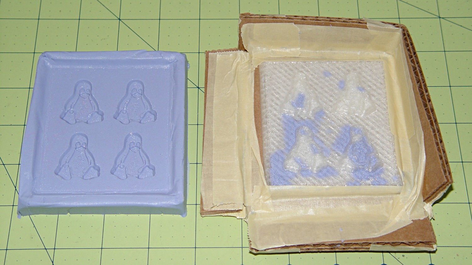
Fast-forward overnight, cut the tape, and peel the silicone negative off the positive:
Tux 2×2 mold – opened
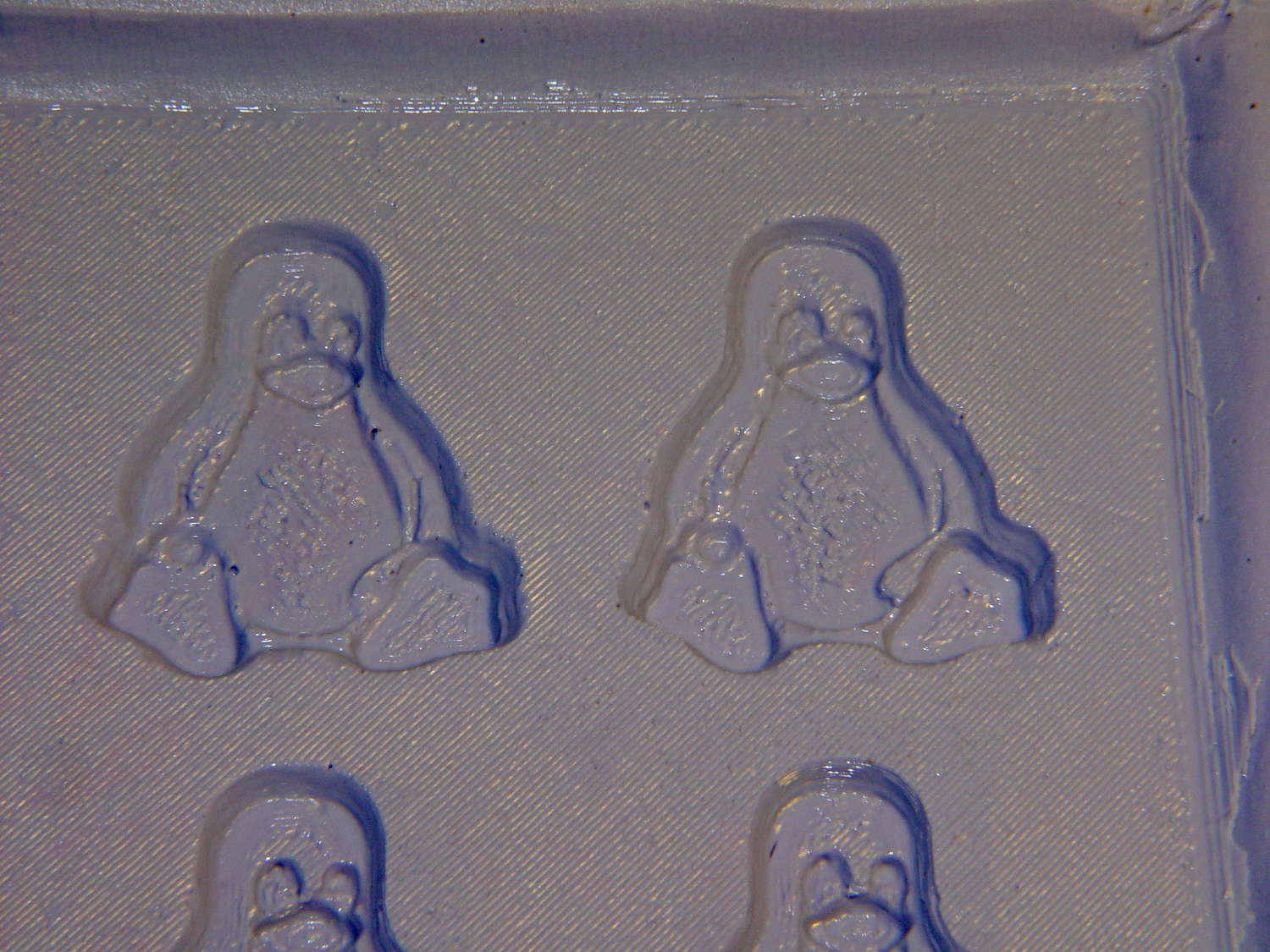
The top surface of the 3D printed positive wasn’t completely water silicone-tight, so the silicone leaked through the top and filled part of the interior. No harm done, but I wasn’t expecting that. The interior of the silicone negative came out pretty well, although you can see some small bubble cavities that may be due to air leaking out through the top of the positive:
Tux 2×2 mold – negative detail
The hand-knitted texture of the 3D printing process comes through very well, which is a Good Thing in this application. If you don’t like that, you can devote considerable time & attention to removing all traces of the production process.
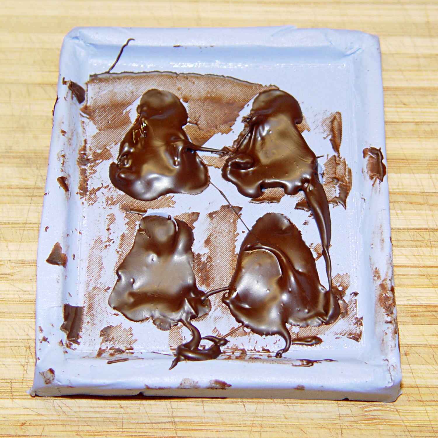
As a proof of concept, I melted and tempered four Dove Dark Chocolate Promises, then poured the chocolate into the cavities:
Tux 2×2 mold – filled
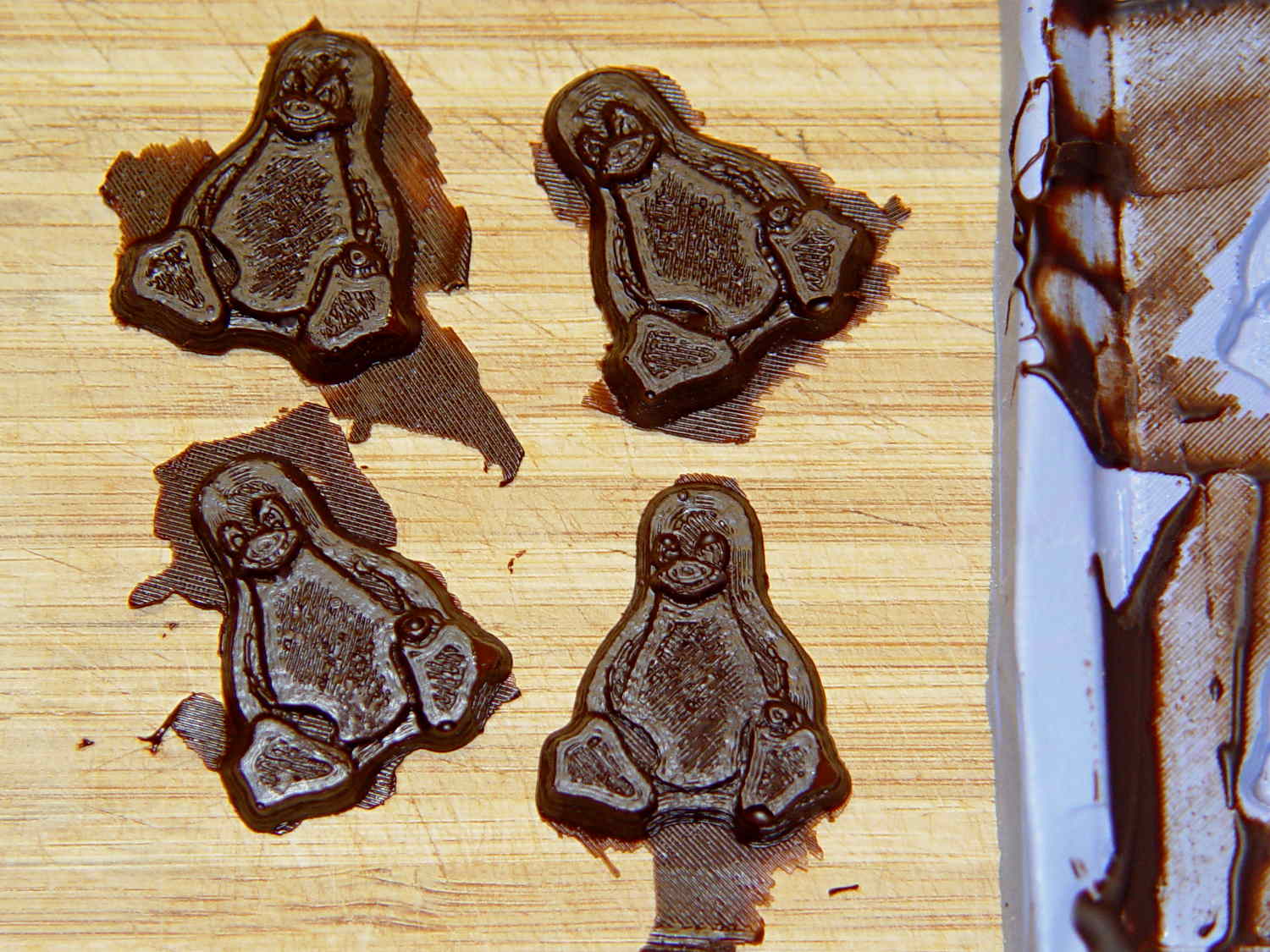
The tempering followed a fairly simple process that worked reasonably well, but the chocolate obviously wasn’t liquid when I poured it. The results looked pretty good, in a textured sort of way:
Tux chocolates – silicone mold
Flushed with success, I tweaked the mold to eliminate the raised lip around the edge, printed another positive plate, mixed up more silicone rubber, paid more attention to getting rid of the bubbles, and got this result:
Tux 2×2 mold 2 – opened
The printed surface still isn’t silicone-tight, which began to puzzle me, but the result looked pretty good.
After some fiddling around, though, I think printing the entire mold array isn’t the way to go. OpenSCAD can handle these 2×2 arrays, but a slightly tweaked Tux model (about which, more later) grossly increased the processing time and memory usage; OpenSCAD (and its CGAL geometry back end) filled all 4 GB of RAM, then blotted up 5 GB of swap space, ran for well over half an hour, and totally locked up the desktop UI for the duration.
It’s certainly infeasible to print the larger array on a sizable base plate that you’d need for a real project. I think printing multiple copies of a single model (duplicating them in the slicer, which is fast & easy), then attaching them to a plain base will work better. There’s no need to print the base plate, either, as a serrated top surface doesn’t buy anything; acrylic (or some such) sheet is cheap, flat, and readily available.
The Bash scripts and OpenSCAD programs below don’t produce exactly the same results you see above, mostly because I screwed around with them while discovering the reasons why doing it this way doesn’t make sense, but they can serve as a starting point if you must convince yourself, too.
This Bash script produces a single positive mold item from a height map image:
// Mold positive pattern from grayscale height map
// Ed Nisley KE4ZNU - March 2014 - adapted from cookie press, added alignment pins

//-----------------
// Mold files

fnMap = "Tux_map.dat";					// override with -D 'fnMap="whatever.dat"'
fnPlate = "Tux_plate.dat";				// override with -D 'fnPlate="whatever.dat"'

DotsPerMM = 3.0;						// overrride with -D DotsPerMM=number

MapHeight = 4.0;						// overrride with -D MapHeight=number

ImageX = 100;							// overrride with -D ImageX=whatever
ImageY = 100;

UsePins = true;

MapScaleXYZ = [1/DotsPerMM,1/DotsPerMM,MapHeight/255];
PlateScaleXYZ = [1/DotsPerMM,1/DotsPerMM,1.0];

echo("Press File: ",fnMap);
echo("Plate File: ",fnPlate);

echo(str("ImageX:",ImageX," ImageY: ", ImageY));
echo(str("Map Height: ",MapHeight));
echo(str("Dots/mm: ",DotsPerMM));
echo(str("Scale Map: ",MapScaleXYZ,"  Plate: ",PlateScaleXYZ));

//- Extrusion parameters - must match reality!

ThreadThick = 0.25;
ThreadWidth = 2.0 * ThreadThick;

//- Buid parameters

PlateThick = IntegerMultiple(1.0,ThreadThick);		// solid plate under press relief

PinOD = 1.75;				// locating pin diameter
PinDepth = PlateThick;		//  ... depth into bottom surface = total length/2
PinOC = 20.0;				// spacing within mold item

echo(str("Pin depth: ",PinDepth," spacing: ",PinOC));

//- Useful info

function IntegerMultiple(Size,Unit) = Unit * ceil(Size / Unit);

HoleWindage = 0.2;

Protrusion = 0.1;						// make holes & unions work correctly

MaxConvexity = 5;						// used for F5 previews in OpenSCAD GUI

ZFuzz = 0.2;							// numeric chaff just above height map Z=0 plane

//-----------------
// Import plate height map, slice off a slab to define outline

module Slab(Thick=1.0) {
	intersection() {
		translate([0,0,Thick/2])
			cube([2*ImageX,2*ImageY,Thick],center=true);
		scale(PlateScaleXYZ)
			difference() {
				translate([0,0,-ZFuzz])
					surface(fnPlate,center=true,convexity=MaxConvexity);
				translate([0,0,-1])
					cube([2*ImageX,2*ImageY,2],center=true);
			}
	}
}

//- Put peg grid on build surface

module ShowPegGrid(Space = 10.0,Size = 1.0) {

	Range = floor(50 / Space);

	for (x=[-Range:Range])
	  for (y=[-Range:Range])
		translate([x*Space,y*Space,Size/2])
			%cube(Size,center=true);
}

//-- convert cylinder to low-count polygon

module PolyCyl(Dia,Height,ForceSides=0) {			// based on nophead's polyholes

  Sides = (ForceSides != 0) ? ForceSides : (ceil(Dia) + 2);

  FixDia = Dia / cos(180/Sides);

  cylinder(r=(FixDia + HoleWindage)/2,
           h=Height,
	   $fn=Sides);
}

//-- Locating pin hole with glue recess
//  Default length is two pin diameters on each side of the split

module LocatingPin(Dia=PinOD,Len=0.0) {

	PinLen = (Len != 0.0) ? Len : (4*Dia);

	translate([0,0,-ThreadThick])
		PolyCyl((Dia + 2*ThreadWidth),2*ThreadThick,4);

	translate([0,0,-2*ThreadThick])
		PolyCyl((Dia + 1*ThreadWidth),4*ThreadThick,4);

	translate([0,0,-(Len/2 + ThreadThick)])
		PolyCyl(Dia,(Len + 2*ThreadThick),4);

}

//- Build it

//ShowPegGrid();

echo("Building mold");
union() {
	difference() {
		Slab(PlateThick + Protrusion);
		if (UsePins)
			for (i=[-1,1])
				translate([0,i*PinOC/2,0])
					rotate(180/4) LocatingPin(Len=2*PinDepth);
	}
	translate([0,0,PlateThick])							// cookie press height map
		scale(MapScaleXYZ)
		difference() {
			translate([0,0,-ZFuzz])
				surface(fnMap,center=true,convexity=MaxConvexity);
			translate([0,0,-1])
				cube([2*ImageX,2*ImageY,2],center=true);
		}
}
This OpenSCAD source code slides a base plate under an array of those mold items, with options for a separate plate using alignment pins or the combined plate-with-molds shown above:
// Positive mold framework for chocolate slabs
// Ed Nisley - KE4ZNU - March 2014

Layout = "FrameMolds";		// FramePins FrameMolds Pin

//- Extrusion parameters must match reality!
//  Print with 2 shells and 3 solid layers

ThreadThick = 0.20;
ThreadWidth = 0.40;

Protrusion = 0.1;			// make holes end cleanly

HoleWindage = 0.2;

//----------------------
// Dimensions

FileName = "Tux_Hi_Profile-positive.stl";	// overrride with -D

Molds = [2,2];					// count of molds within framework

MoldOC = [45.0,50.0];			// on-center spacing of molds
MoldSlab = 1.0;					// thickness of slab under molds

BaseThick = 3.0;

BaseSize = [(Molds[0]*MoldOC[0] + 0),(Molds[1]*MoldOC[1] + 0),BaseThick];
echo(str("Overall base: ",BaseSize));

PinOD = 1.75;					// locating pin diameter
PinLength = 2.0;				//  ... total length
PinOC = 20.0;				// spacing within mold item

//----------------------
// Useful routines

//- Put peg grid on build surface

module ShowPegGrid(Space = 10.0,Size = 1.0) {

	RangeX = floor(100 / Space);
	RangeY = floor(125 / Space);

	for (x=[-RangeX:RangeX])
		for (y=[-RangeY:RangeY])
			translate([x*Space,y*Space,Size/2])
			%cube(Size,center=true);

}

module PolyCyl(Dia,Height,ForceSides=0) {			// based on nophead's polyholes

  Sides = (ForceSides != 0) ? ForceSides : (ceil(Dia) + 2);

  FixDia = Dia / cos(180/Sides);

  cylinder(r=(FixDia + HoleWindage)/2,
           h=Height,
	   $fn=Sides);
}

// Locating pin hole with glue recess
//  Default length is two pin diameters on each side of the split

module LocatingPin(Dia=PinOD,Len=0.0) {

	PinLen = (Len != 0.0) ? Len : (4*Dia);

	translate([0,0,-ThreadThick])
		PolyCyl((Dia + 2*ThreadWidth),2*ThreadThick,4);

	translate([0,0,-2*ThreadThick])
		PolyCyl((Dia + 1*ThreadWidth),4*ThreadThick,4);

	translate([0,0,-(Len/2 + ThreadThick)])
		PolyCyl(Dia,(Len + 2*ThreadThick),4);

}

module LocatingPins(Length) {
	for (i=[-1,1])
	translate([0,i*PinOC/2,0])
		rotate(180/4)
		LocatingPin(Len=Length);
}

//-- import a single mold item

module MoldItem() {

//	intersection() {
		import(FileName,convexity=10);
//		cube([100,100,3],center=true);
//	}
}

//-- Overall frame shape

module Frame() {

//	translate([0,0,BaseSize[2]/2])		// platform under molds
//		cube(BaseSize,center=true);

	difference() {
		hull()
			for (i=[-1,1], j=[-1,1])
				translate([i*BaseSize[0]/2,j*BaseSize[1]/2,0])
					sphere(r=BaseThick);
		translate([0,0,-BaseThick])
			cube(2*BaseSize,center=true);
	}

}

//- Build it

ShowPegGrid();

if (Layout == "Pin")
	LocatingPin(Len=PinLength);

if (Layout == "Frame")
	Frame();

if (Layout == "FramePins")
	difference() {
		Frame();

		translate([-MoldOC[0]*(Molds[0] - 1)/2,-MoldOC[1]*(Molds[1] - 1)/2,0])
			for (i=[0:Molds[0]-1],j=[0:Molds[1]-1])
				translate([i*MoldOC[0],j*MoldOC[1],BaseSize[2]])
					LocatingPins(BaseThick);
	}

if (Layout == "FrameMolds") {
	Frame();
	translate([-MoldOC[0]*(Molds[0] - 1)/2,-MoldOC[1]*(Molds[1] - 1)/2,0])
		for (i=[0:Molds[0]-1],j=[0:Molds[1]-1])
			translate([i*MoldOC[0],j*MoldOC[1],BaseThick - MoldSlab + Protrusion])
			MoldItem();
}