The Smell of Molten Projects in the Morning

Ed Nisley's Blog: Shop notes, electronics, firmware, machinery, 3D printing, laser cuttery, and curiosities. Contents: 100% human thinking, 0% AI slop.

Tag: M2

Using and tweaking a Makergear M2 3D printer

  • 3D Printed Chain Mail Armor: Cosplay Edition

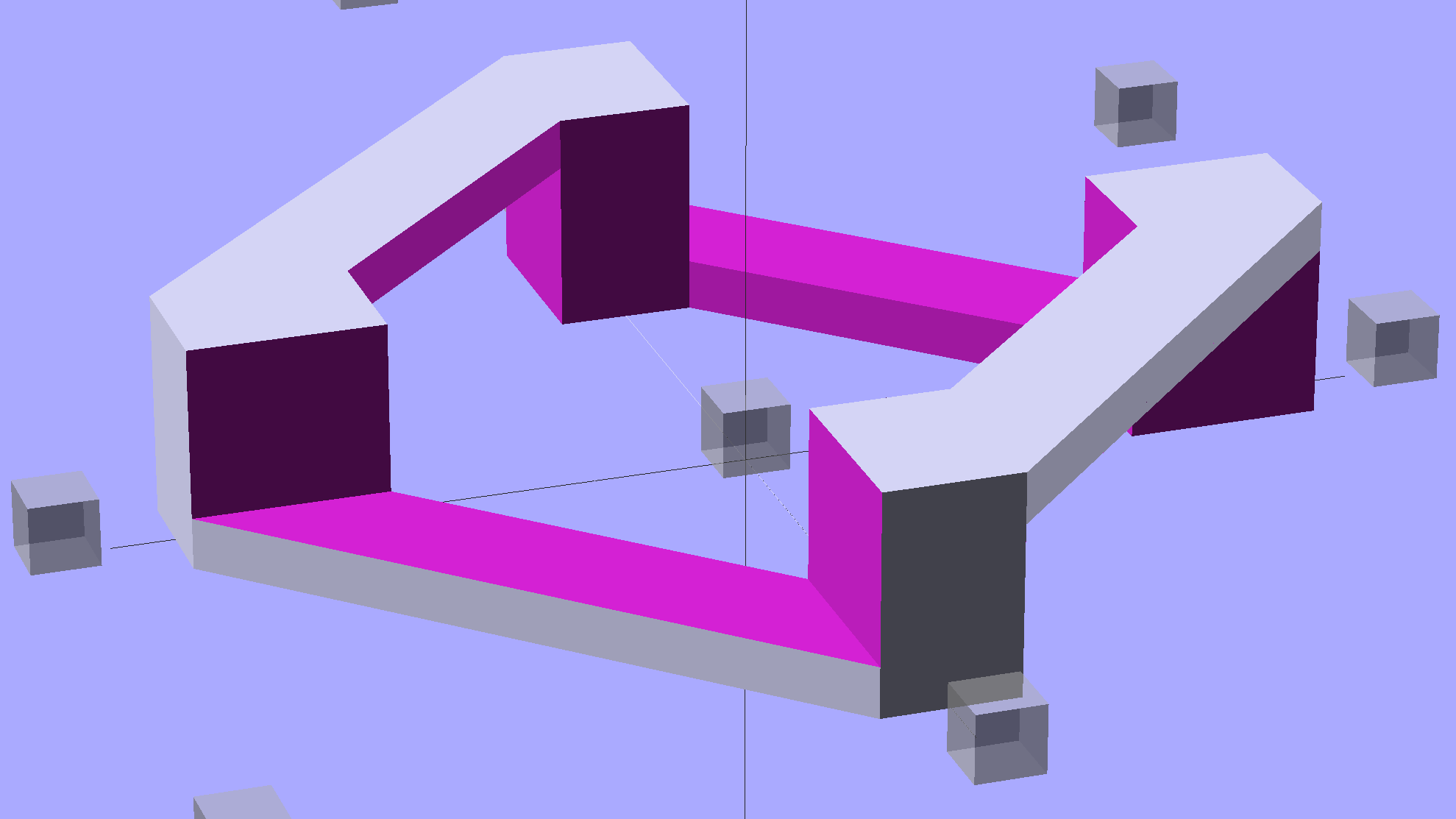
    Starting from the improved chain mail link design, extend the top bars enough to clear the cross links, then bridge across them to form a flat cap:

    Chain Mail - Armor and Link
    Chain Mail – Armor and Link

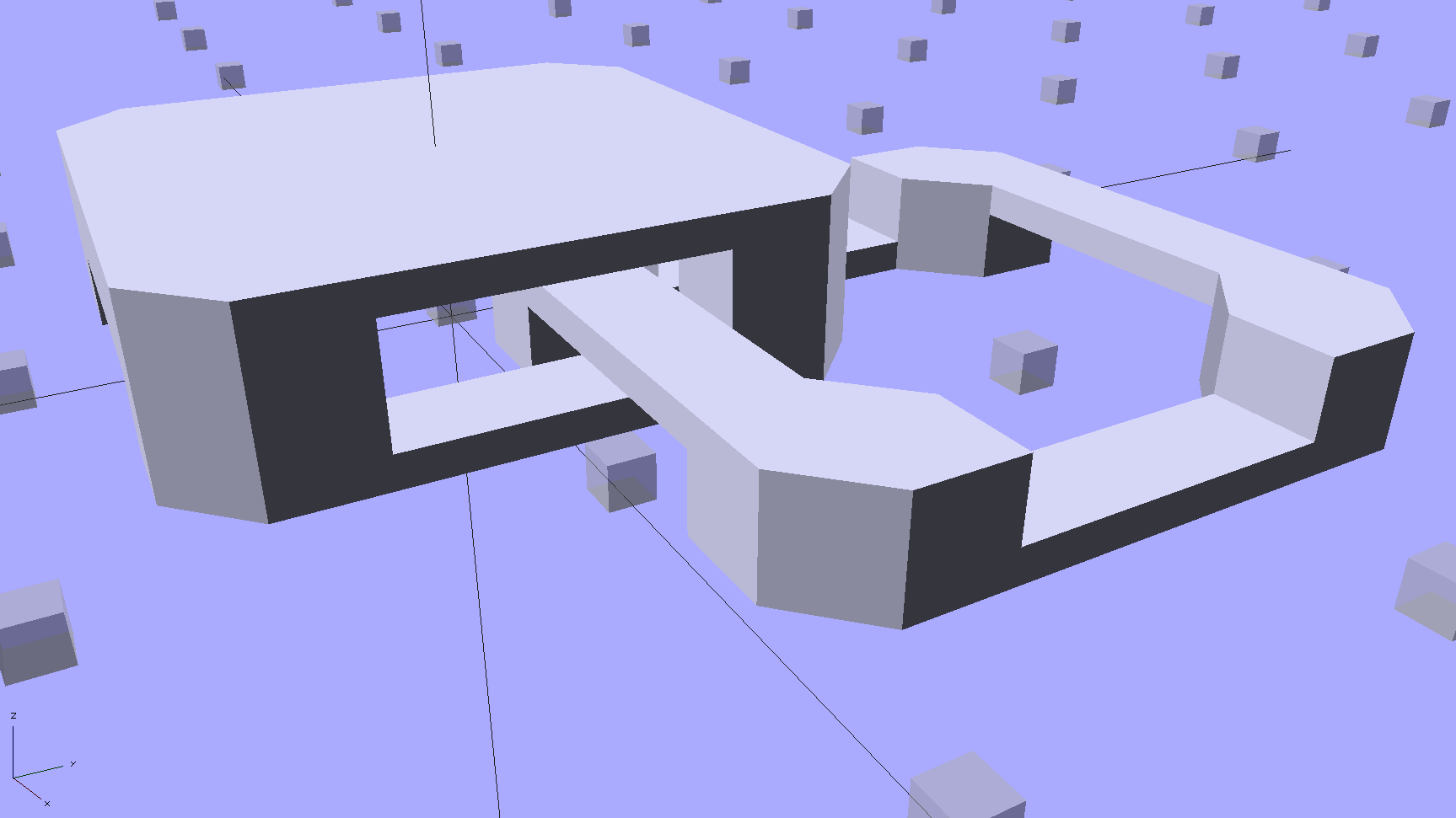
    The OpenSCAD code makes the links as small as they can possibly be, based on the bar size and clearances, then rounds up to a multiple of the thread width so the flat cap will fill properly. Given the extrusion thread dimensions and the bar sizes, the OpenSCAD code computes everything else: the link model matches the slicer settings that define the printer’s output.

    Given:

    • Thread: 0.4 mm wide x 0.2 mm thick
    • Bar: 6 thread wide x 4 thread thick = 2.4 x 0.8 mm
    • Clearances: 2 thread horizontal x 5 thread vertical = 0.8 x 1.0 mm

    All the links measure 15.6 mm from side to side, the short connecting links are 2.6 mm tall, and the flat caps are 4.4 mm tall. Interlinked links sit 8.2 mm on center = half the link side plus one thread width clearance, which is 16.4 mm on center for adjacent links.

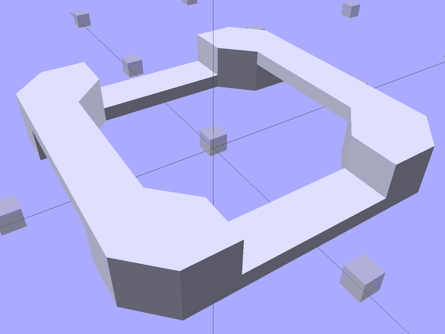
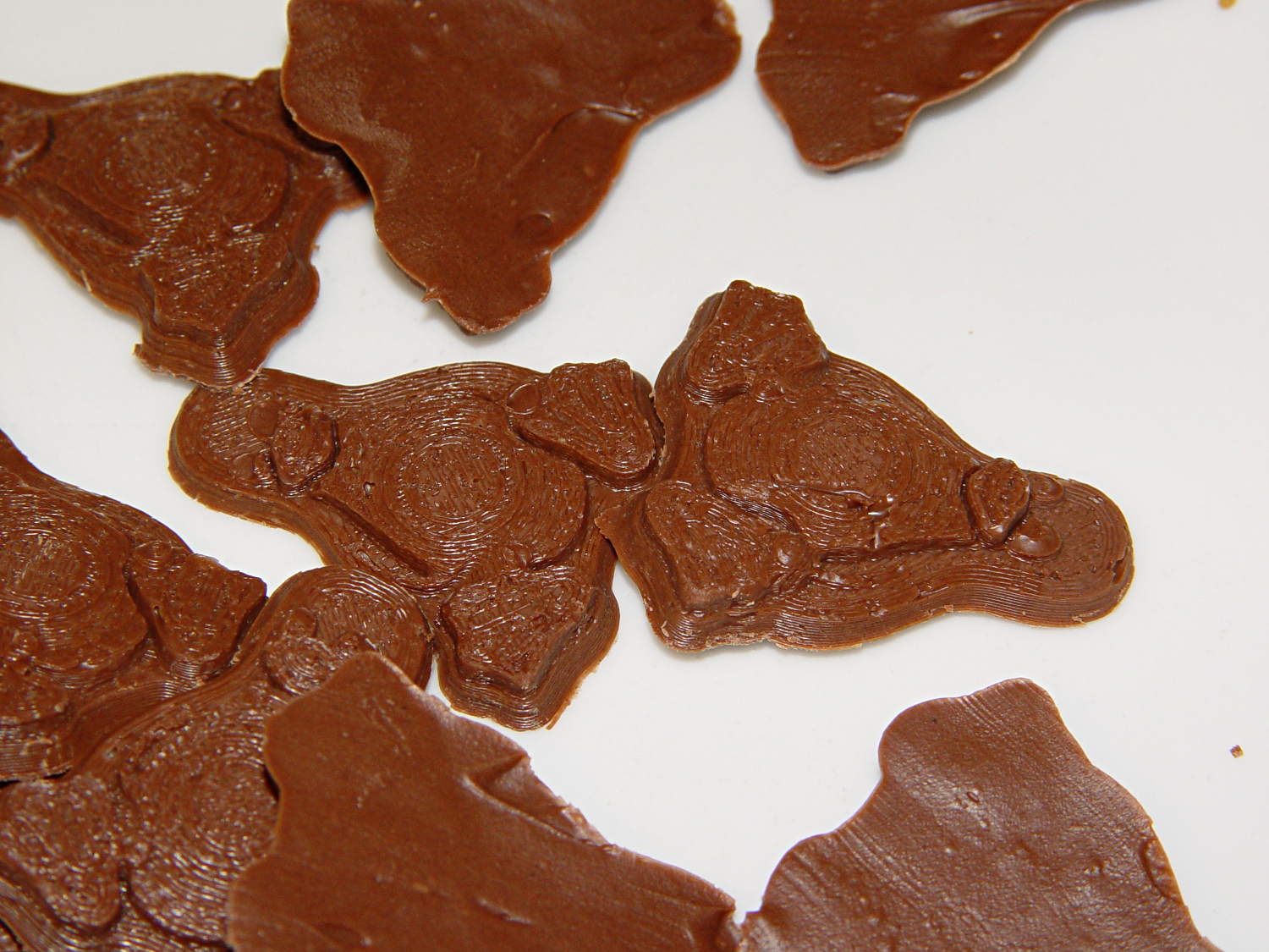
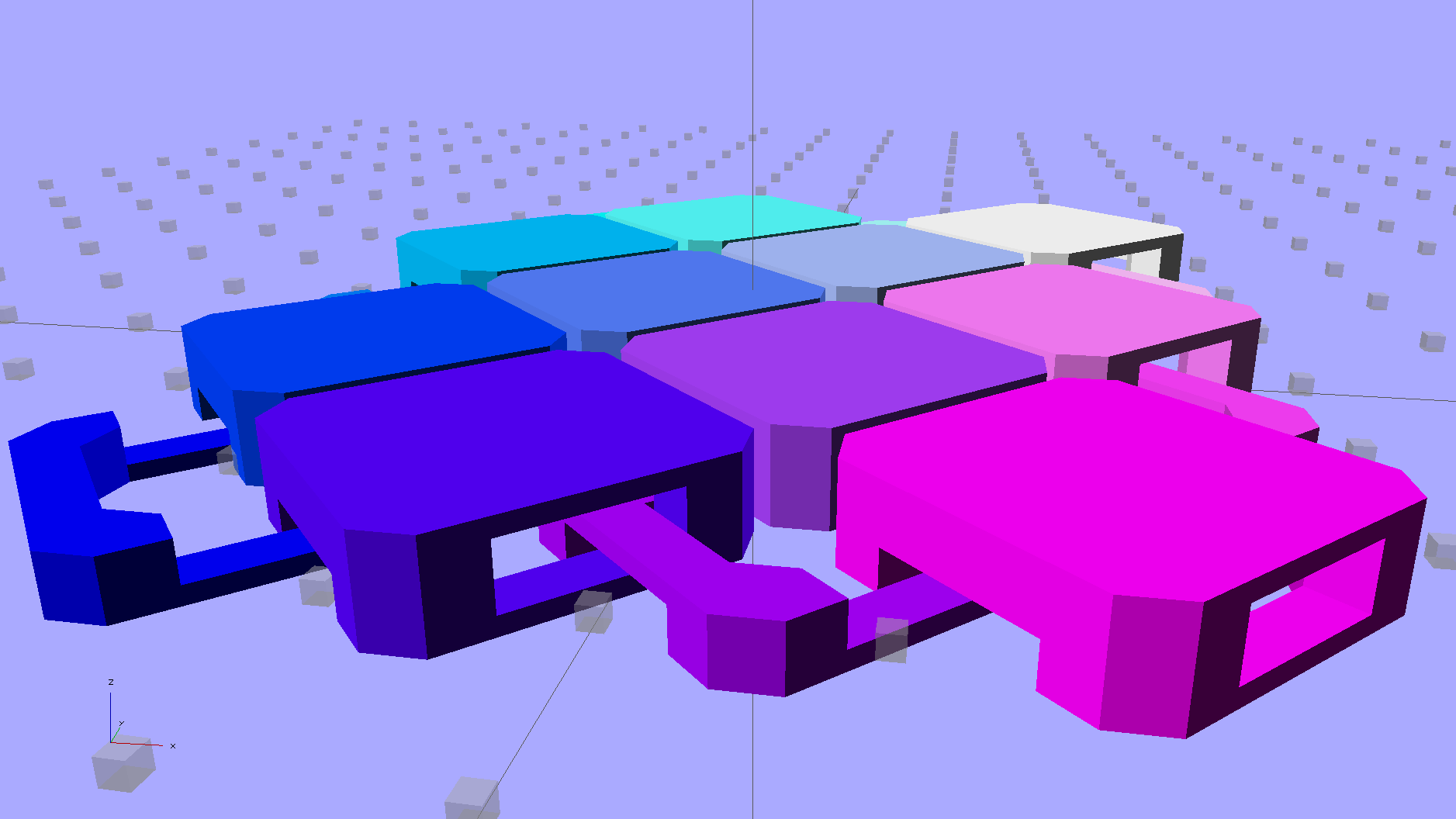
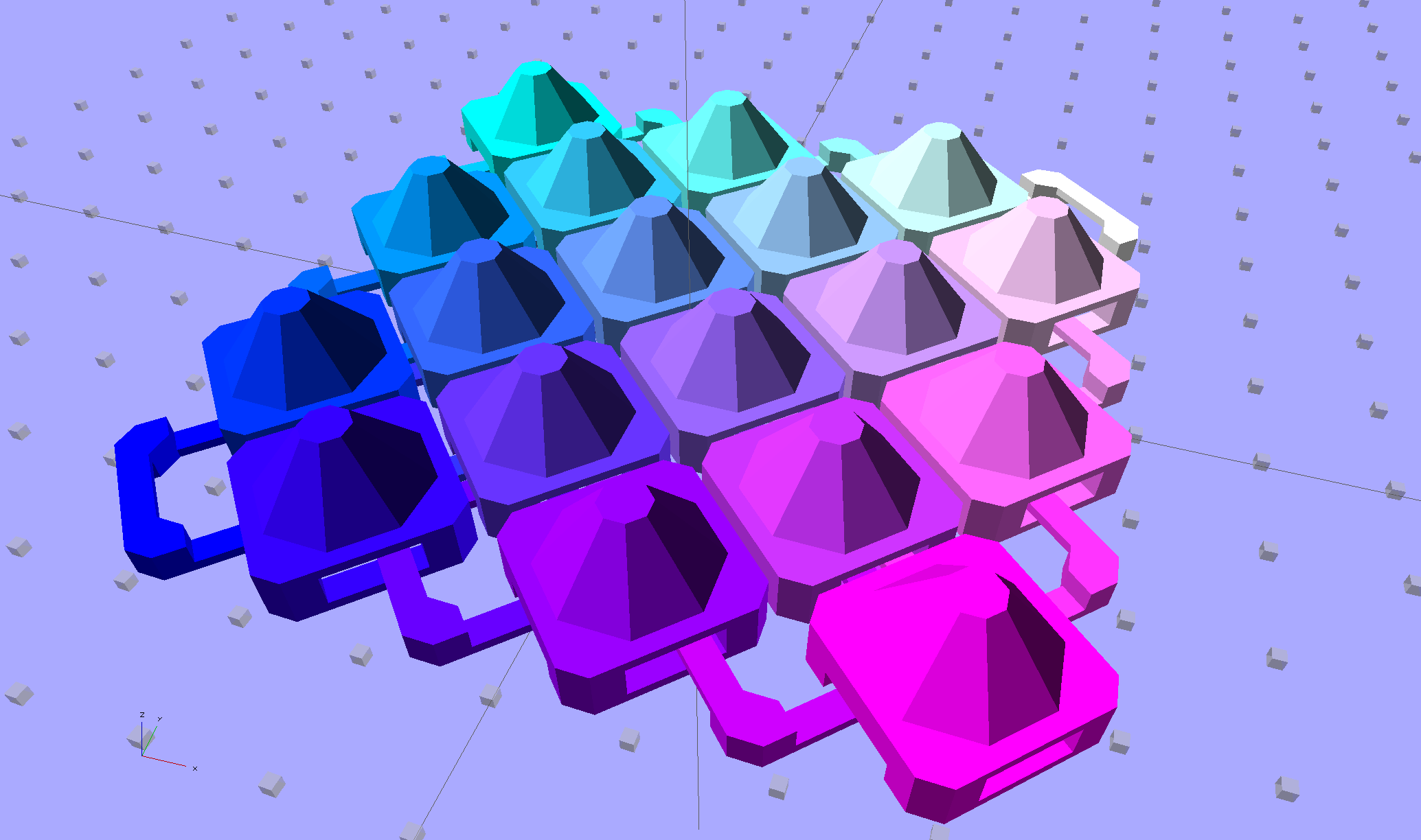
    Duplicated appropriately, the caps resemble turtle armor:

    Chain Mail - Flat Armor
    Chain Mail – Flat Armor

    Which look about the same in real life, minus the cheerful colors:

    Armor Buttons - on platform - side
    Armor Buttons – on platform – side

    Now, however, you can plunk an armor button atop the cap:

    Chain Mail Armor - 4 sided
    Chain Mail Armor – 4 sided

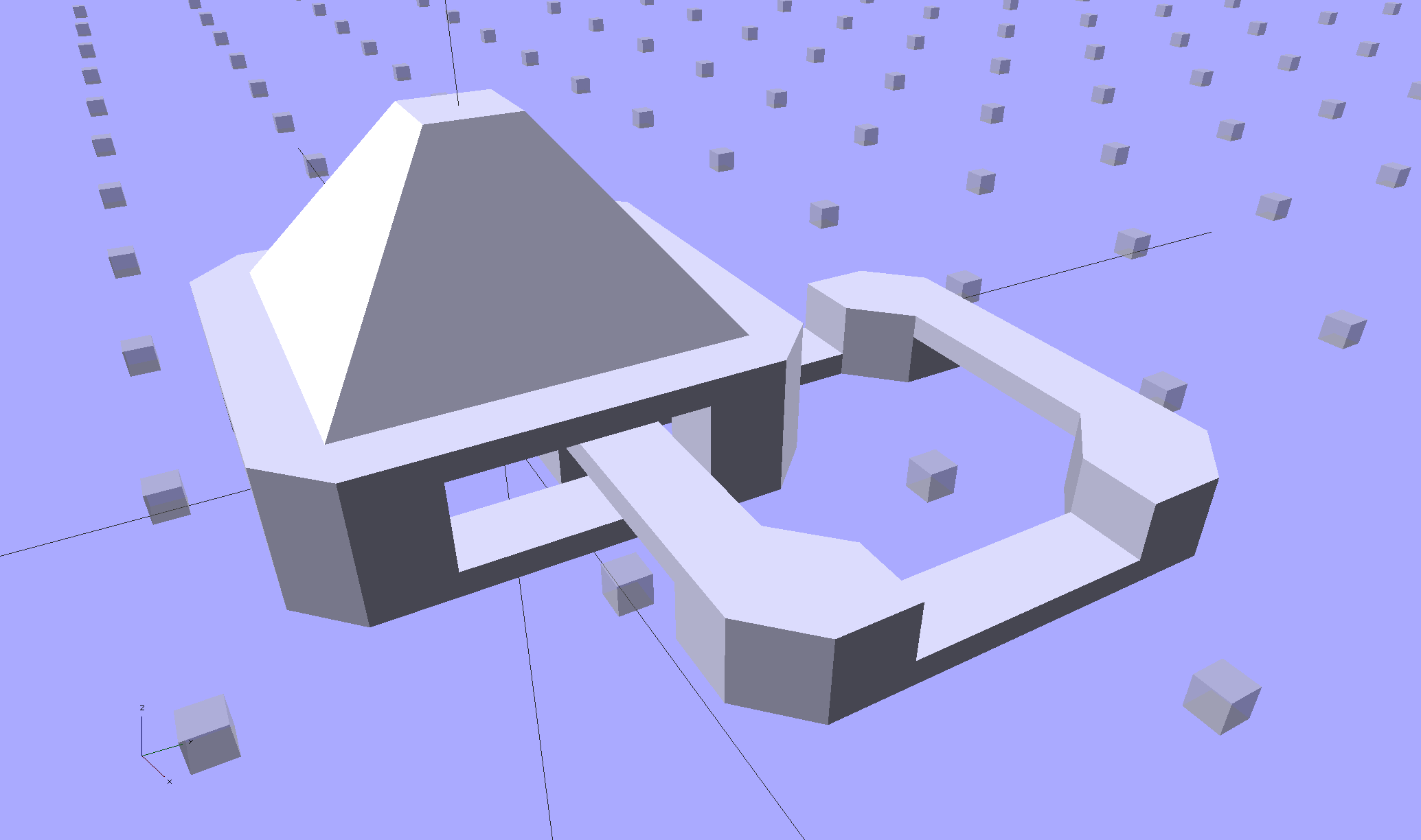
    With any number of sides:

    Chain Mail Armor - 6 sided
    Chain Mail Armor – 6 sided

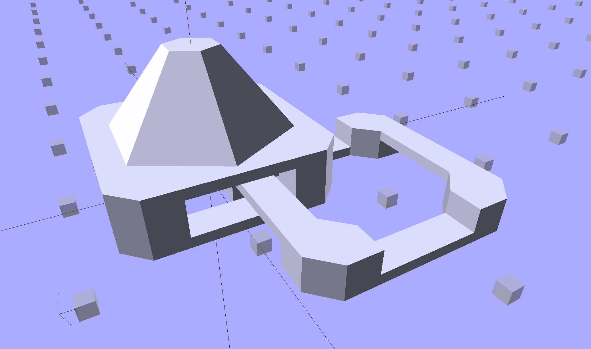
    Up to a truncated cone:

    Chain Mail Armor - 24 sided
    Chain Mail Armor – 24 sided

    The flat tip makes the button more durable and user-friendly, but you can make it a bit more pointy if you favor that sort of thing. The button adds 6 mm to the link base, making armor links 10.4 mm tall.

    Other printable stuff could fit on that cap: letters, decorations, widgets, whatever.

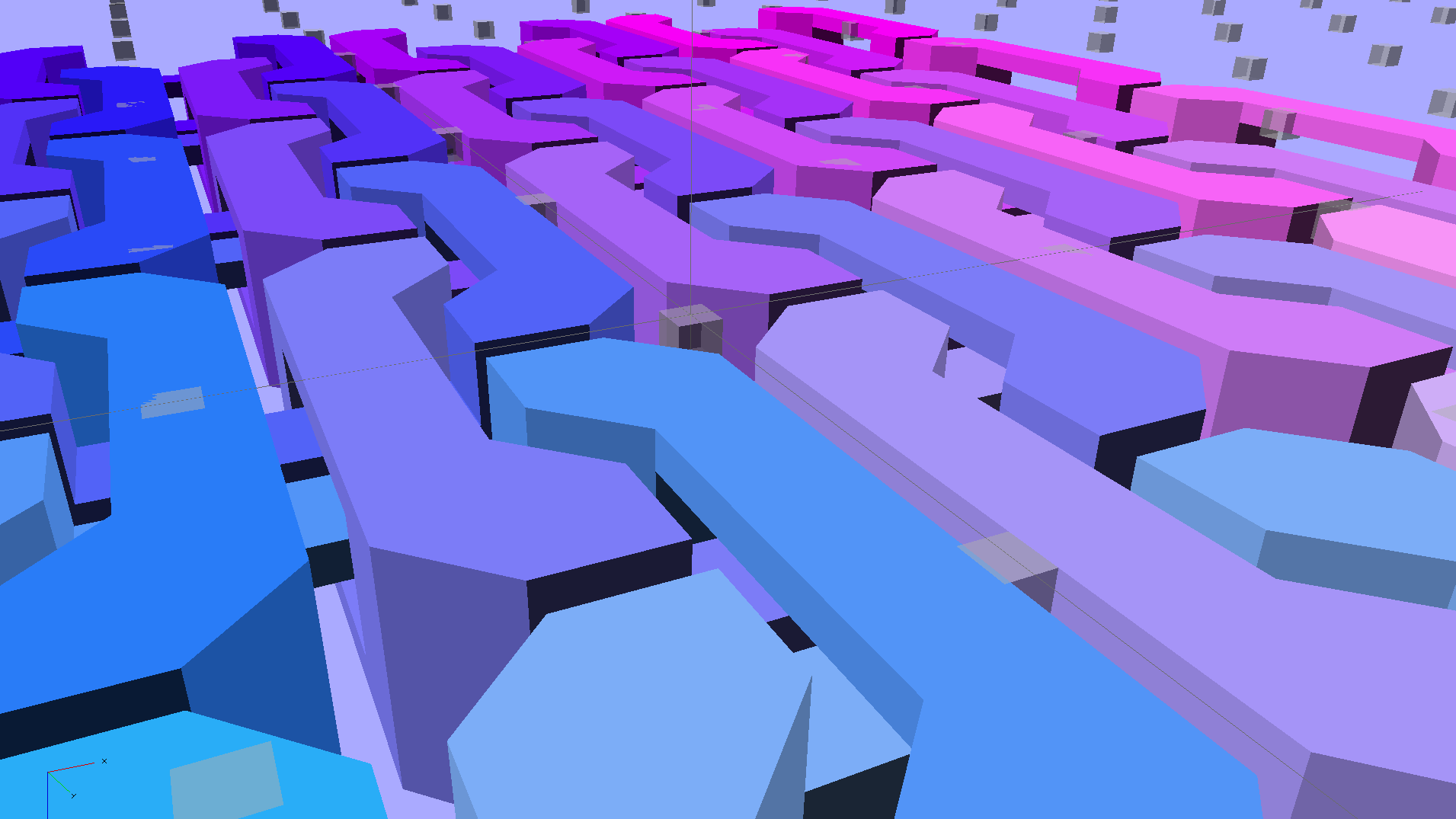
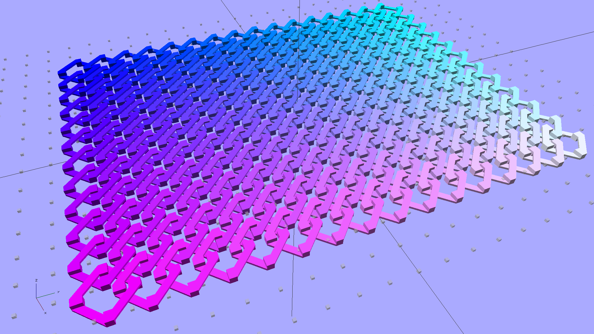
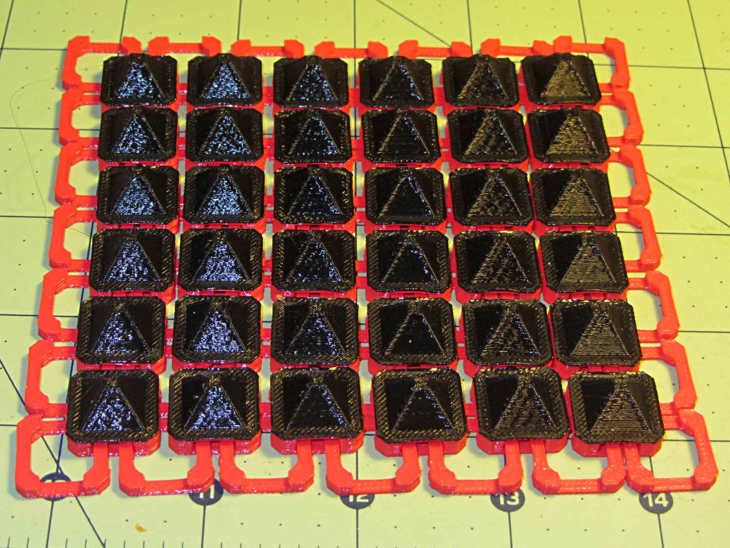
    I think square armor buttons look ever so imposing when they’re arrayed in a sheet:

    Chain Mail Armor - square - 4 sided
    Chain Mail Armor – square – 4 sided

    The general idea being that you could attach the armor sheet to a cloth / leather backing to form a gauntlet or greave; the border of bottom links around the button array should serve for that purpose.

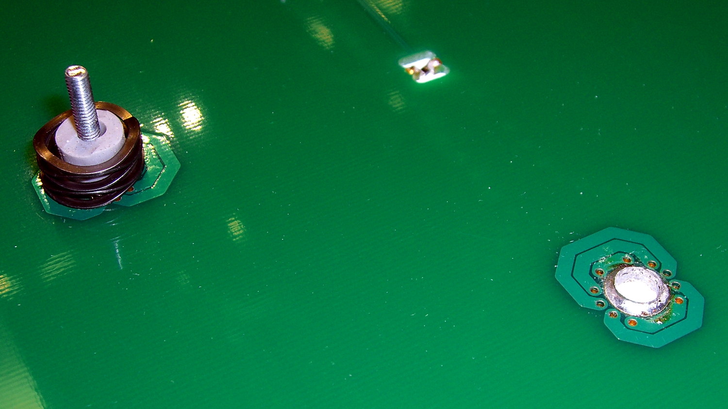
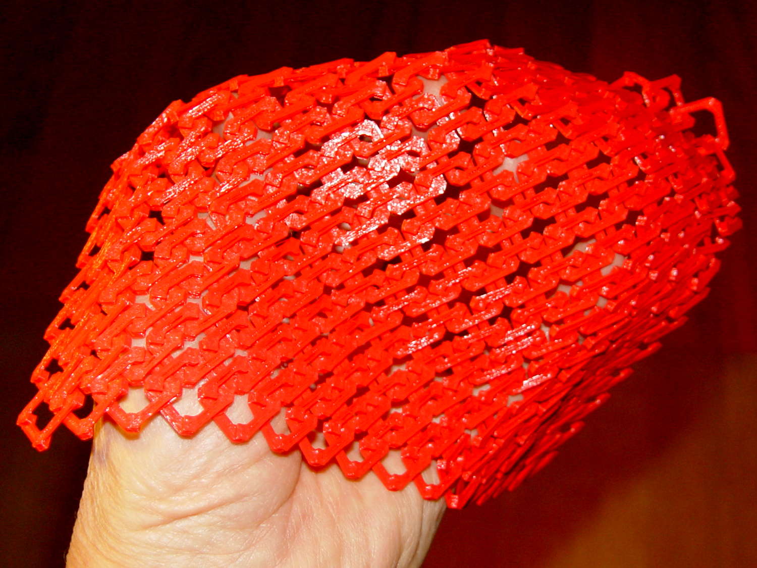
    The plastic prints just like the model and pops off the M2’s platform ready to use, with no finishing required:

    Chain Mail Armor - square on desk
    Chain Mail Armor – square on desk

    The two-color effect came from hot-swapping black filament as the red PLA ran out. The 6×6 armor button array and the 7×7 connecting link array holding it together required 14 meters of filament and I guesstimated the red spool held 9 meters: I was ready when the last of the red vanished just after completing the bridging layer under the flat caps. Filament swaps work reasonably well; I’d hate to do that on a production basis.

    If you don’t mind my saying so, everybody thinks it’s spectacular:

    Chain Mail Armor - square on arm
    Chain Mail Armor – square on arm

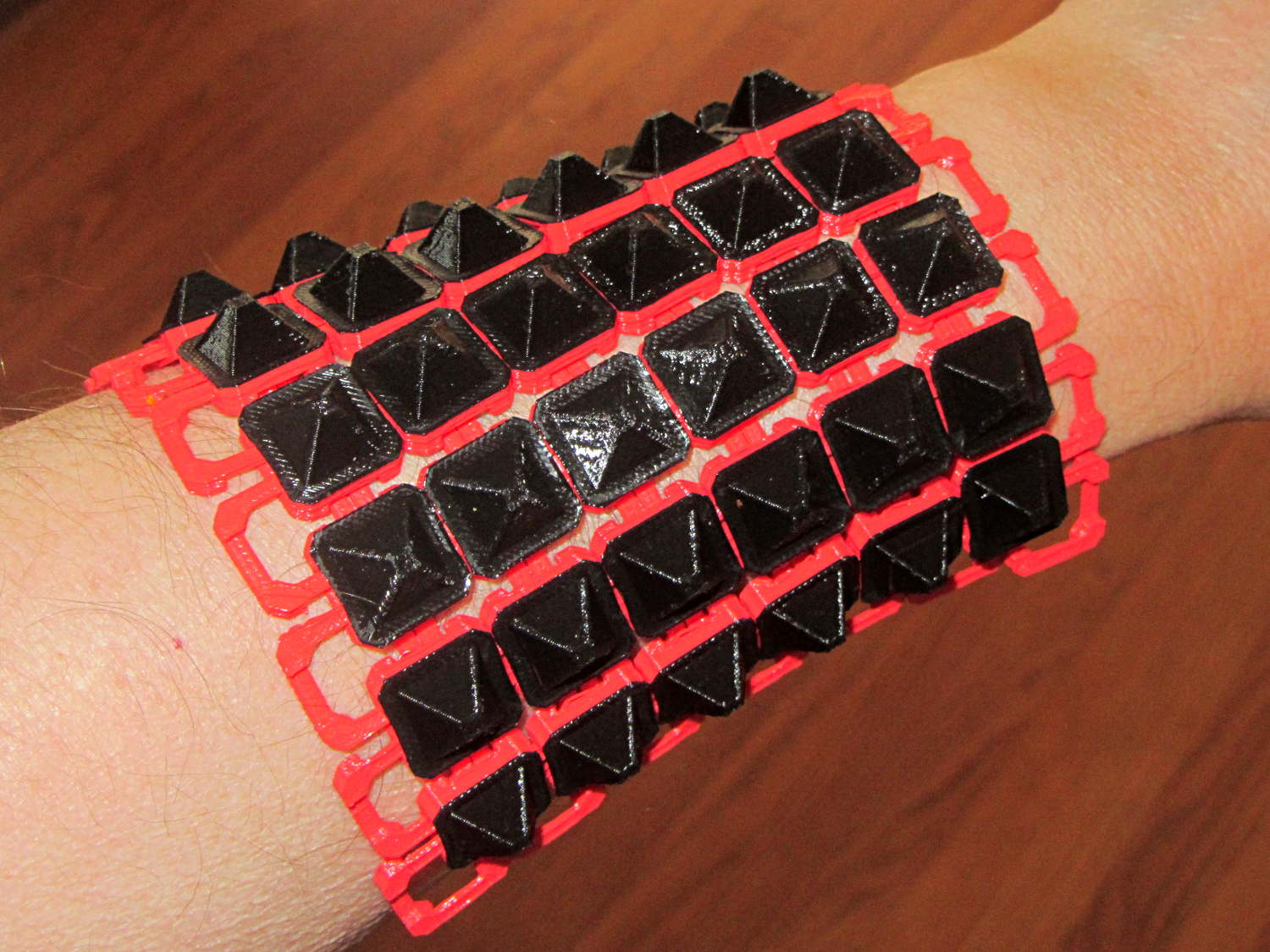
    The sheet has a definite “grain” defined by the orientation of the bottom links, making it far more bendy in one direction than the other:

    Chain Mail Armor - square rolled
    Chain Mail Armor – square rolled

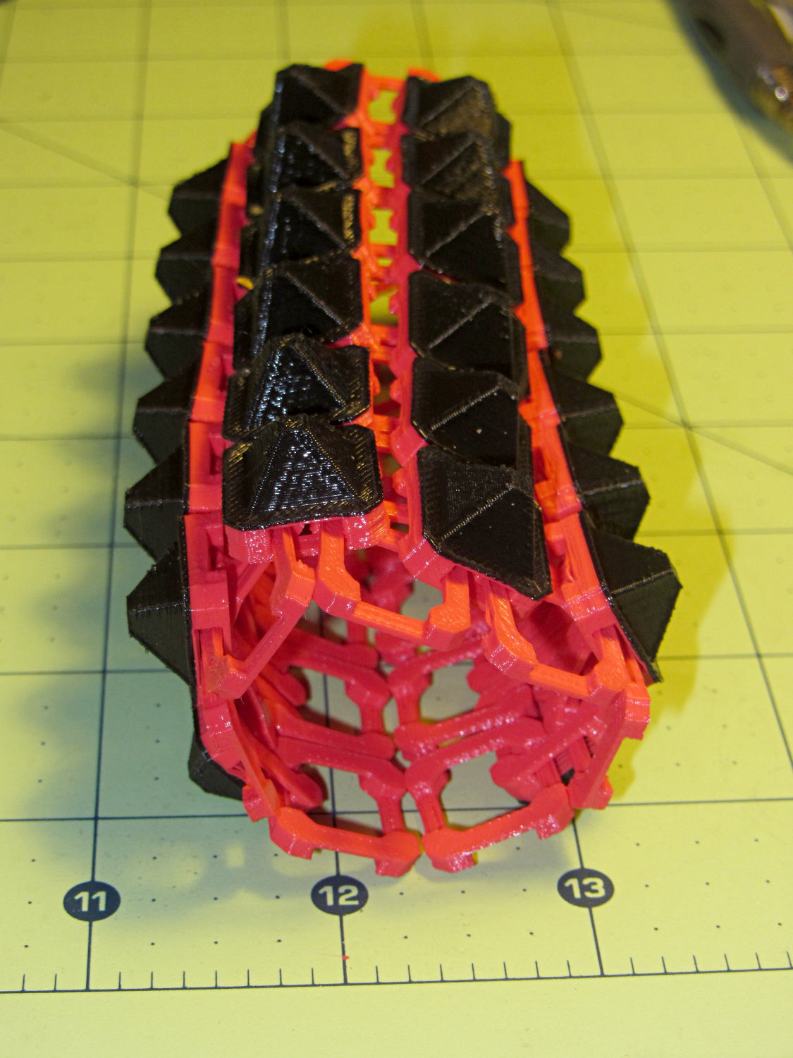
    The sheet layout orients the more-bendy direction along the M2’s (longer) Y axis, so that sheets can wrap snugly around your arm (or leg) and extend straight-ish along the bones in the other direction. That should be configurable, I think.

    There’s an option to rotate the links by 45° to produce diamond-theme arrays:

    Chain Mail Armor - diamond - 8 sided
    Chain Mail Armor – diamond – 8 sided

    Which would make good patch armor, if you’re into that sort of thing:

    Chain Mail Armor - diamond on hand
    Chain Mail Armor – diamond on hand

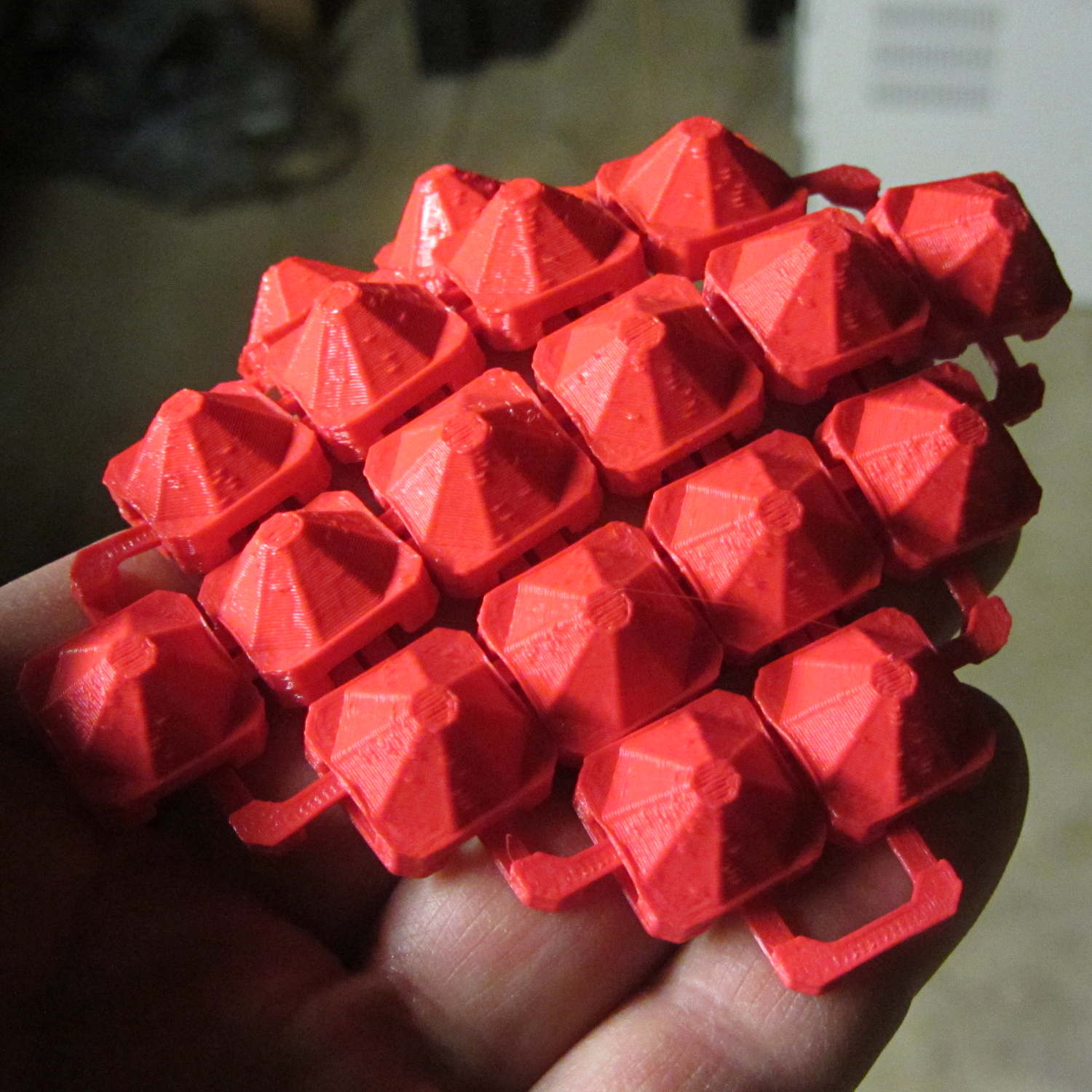
    Those have octagonal buttons, which IMHO don’t look nearly as crisp as the four-sided version.

    Ah! I should generalize the diamond rotation option to select all four useful rotations.

    The 6×6 square sheet requires three hours on the M2, with the intial print time estimates being low by nearly a factor of two. The M2 has a 200×250 mm platform and I’ll definitely try a full-size array just to see how it works.

    The OpenSCAD source code, which stands badly in need of refactoring:

    // Chain Mail Armor Buttons
    // Ed Nisley KE4ZNU - November 2014
    
    Layout = "Build";			// Link Button LB Build
    
    //-------
    //- Extrusion parameters must match reality!
    //  Print with 1 shell and 2+2 solid layers
    
    ThreadThick = 0.20;
    ThreadWidth = 0.40;
    
    HoleWindage = 0.2;
    
    Protrusion = 0.1;			// make holes end cleanly
    
    function IntegerMultiple(Size,Unit) = Unit * ceil(Size / Unit);
    
    //-------
    // Dimensions
    
    //- Set maximum sheet size
    
    SheetSizeX = 70;
    SheetSizeY = 80;
    
    //- Diamond or rectangular sheet?
    
    Diamond = false;					// true = rotate 45 degrees, false = 0 degrees for square
    ArmorButton = true;					// true = build button atop cap
    
    // Link bar sizes
    
    BarWidth = 6 * ThreadWidth;
    BarThick = 4 * ThreadThick;
    
    BarClearance = 5*ThreadThick;		// vertical clearance above & below bars
    
    //-- Compute link sizes from those values
    
    // Absolute minimum base link: bar width + corner angle + build clearance around bars
    //  rounded up to multiple of thread width to ensure clean filling
    BaseSide = IntegerMultiple((4*BarWidth + 2*BarWidth/sqrt(2) + 3*(2*ThreadWidth)),ThreadWidth);
    
    BaseHeight = 2*BarThick + BarClearance;           // both bars + clearance
    
    echo(str("BaseSide: ",BaseSide," BaseHeight: ",BaseHeight));
    
    BaseOutDiagonal = BaseSide*sqrt(2) - BarWidth;
    BaseInDiagonal = BaseSide*sqrt(2) - 2*(BarWidth/2 + BarWidth*sqrt(2));
    
    echo(str("Outside diagonal: ",BaseOutDiagonal));
    
    //- On-center distance measured along coordinate axis
    
    LinkOC = BaseSide/2 + ThreadWidth;
    
    LinkSpacing = Diamond ? (sqrt(2)*LinkOC) : LinkOC;
    echo(str("Base spacing: ",LinkSpacing));
    
    //- Compute how many links fit in sheet
    
    MinLinksX = ceil((SheetSizeX - (Diamond ? BaseOutDiagonal : BaseSide)) / LinkSpacing);
    MinLinksY = ceil((SheetSizeY - (Diamond ? BaseOutDiagonal : BaseSide)) / LinkSpacing);
    echo(str("MinLinks X: ",MinLinksX," Y: ",MinLinksY));
    
    NumLinksX = ((0 == (MinLinksX % 2)) && !Diamond) ? MinLinksX + 1 : MinLinksX;
    NumLinksY = ((0 == (MinLinksY % 2) && !Diamond)) ? MinLinksY + 1 : MinLinksY;
    echo(str("Links X: ",NumLinksX," Y: ",NumLinksY," Total: ",NumLinksX*NumLinksY));
    
    //- Armor button base
    
    CapThick = BarThick;
    
    ButtonHeight = BaseHeight + BarClearance + CapThick;
    echo(str("ButtonHeight: ",ButtonHeight));
    
    //- Armor ornament size & shape
    
    ArmorSides = 4;
    ArmorAngle = true ? 180/ArmorSides : 0;			// rotate half a side?
    
    ArmorThick = IntegerMultiple(6,ThreadThick);	// keep it relatively short
    
    ArmorOD = 1.1 * BaseSide;						// tune for best fit at base
    
    ArmorID = 10 * ThreadWidth;						// make the tip wide & strong
    
    //-------
    
    module ShowPegGrid(Space = 10.0,Size = 1.0) {
    
      RangeX = floor(95 / Space);
      RangeY = floor(125 / Space);
    
    	for (x=[-RangeX:RangeX])
    	  for (y=[-RangeY:RangeY])
    		translate([x*Space,y*Space,Size/2])
    		  %cube(Size,center=true);
    
    }
    
    //-------
    // Create base link
    
    module BaseLink() {
    
    render()
    	rotate(Diamond ? 45 : 90)			// 90 = more bendy around X axis
    		difference() {
    			translate([0,0,BaseHeight/2]) {
    				difference(convexity=2) {
    					intersection() {		// outside shape
    						cube([BaseSide,BaseSide,BaseHeight],center=true);
    						rotate(45)
    							cube([BaseOutDiagonal,BaseOutDiagonal,BaseHeight],center=true);
    					}
    					intersection() {		// inside shape
    						cube([(BaseSide - 2*BarWidth),
    							  (BaseSide - 2*BarWidth),
    							  (BaseHeight + 2*Protrusion)],
    							 center=true);
    						rotate(45)
    							cube([BaseInDiagonal,
    								  BaseInDiagonal,
    								  (BaseHeight +2*Protrusion)],
    								 center=true);
    					}
    				}
    			}
    
    			translate([0,0,(BaseHeight/2 + BarThick)])
    				cube([(BaseSide - 2*BarWidth - 2*BarWidth/sqrt(2)),
    					  (2*BaseSide),
    					  BaseHeight],
    					 center=true);
    			translate([0,0,(BaseHeight - BaseHeight/2 - BarThick)])
    				cube([(2*BaseSide),
    					  (BaseSide - 2*BarWidth - 2*BarWidth/sqrt(2)),
    					  BaseHeight],
    					 center=true);
    		}
    }
    
    //-------
    // Create button link
    
    module ButtonLink() {
    
    render()
    	rotate(Diamond ? 45 : 90)			// 90 = more bendy around X axis
    		union() {
    			difference() {
    				translate([0,0,ButtonHeight/2])		// outside shape
    					intersection() {
    						cube([BaseSide,BaseSide,ButtonHeight],center=true);
    						rotate(45)
    							cube([BaseOutDiagonal,BaseOutDiagonal,ButtonHeight],center=true);
    					}
    				translate([0,0,(BaseHeight + BarClearance - Protrusion)/2])
    					intersection() {		// inside shape
    						cube([(BaseSide - 2*BarWidth),
    								(BaseSide - 2*BarWidth),
    								(BaseHeight + BarClearance + Protrusion)],
    								center=true);
    						rotate(45)
    							cube([BaseInDiagonal,
    									BaseInDiagonal,
    									(BaseHeight + BarClearance + Protrusion)],
    									center=true);
    				}
    
    				translate([0,0,((BarThick + 2*BarClearance)/2 + BarThick)])
    					cube([(BaseSide - 2*BarWidth - 2*BarWidth/sqrt(2)),
    						(2*BaseSide),
    						BarThick + 2*BarClearance],
    						center=true);
    
    				translate([0,0,(BaseHeight/2 - BarThick)])
    					cube([(2*BaseSide),
    						(BaseSide - 2*BarWidth - 2*BarWidth/sqrt(2)),
    						BaseHeight],
    						center=true);
    
    			}
    
    			if (ArmorButton)
    				translate([0,0,(ButtonHeight - Protrusion)])		// armor on cap
    					rotate(ArmorAngle)
    					cylinder(d1=ArmorOD,
    							 d2=ArmorID,
    							 h=(ArmorThick + Protrusion),
    							 $fn=ArmorSides);
    		}
    }
    
    //-------
    // Build it!
    
    ShowPegGrid();
    
    if (Layout == "Link") {
    	BaseLink();
    }
    
    if (Layout == "Button") {
    	ButtonLink();
    }
    
    if (Layout == "LB") {
    	ButtonLink();
    	translate([LinkSpacing,LinkSpacing,0])
    		BaseLink();
    }
    
    if (Layout == "Build") {
    	for (ix = [0:(NumLinksX - 1)],
    		 iy = [0:(NumLinksY - 1)])
    			assign(x = (ix - (NumLinksX - 1)/2)*LinkSpacing,
    				   y = (iy - (NumLinksY - 1)/2)*LinkSpacing)
    			translate([x,y,0])
    			color([(ix/(NumLinksX - 1)),(iy/(NumLinksY - 1)),1.0])
    				if (Diamond)
    					if ((ix + iy) % 2)						// armor at odd,odd & even, even points
    						ButtonLink();
    					else
    						BaseLink();							// connectors otherwise
    				else
    					if ((iy % 2) && (ix % 2))				// armor at odd,odd points
    						ButtonLink();
    					else if ((!(iy % 2) && !(ix % 2)))		// connectors at even,even points
    						BaseLink();
    }
    
    
  • Improved Chain Mail Link

    The rectangular posts in my chain mail resemble Zomboe’s original design, but with dimensions computed directly from the bar (and, thus, thread) widths and thicknesses to ensure good fill and simple bridging:

    Chain Mail Link
    Chain Mail Link

    They fit together well, but the angled post edges make the bridge threads longer than absolutely necessary along the outside edge of each link:

    Chain Mail Sheet - detail
    Chain Mail Sheet – detail

    A bit of fiddling produces a squared-off version:

    Chain Mail Link - Improved Posts
    Chain Mail Link – Improved Posts

    Which nest together like this:

    Chain Mail - Improved Posts - Bottom View
    Chain Mail – Improved Posts – Bottom View

    Now all the bridge threads have the same length, which should produce better results.

    The OpenSCAD source code for the link:

    module BaseLink() {
    
    	render(convexity=2)
    		difference() {
    			translate([0,0,BaseHeight/2]) {
    				difference(convexity=2) {
    					intersection() {		// outside shape
    						cube([BaseSide,BaseSide,BaseHeight],center=true);
    						rotate(45)
    							cube([BaseOutDiagonal,BaseOutDiagonal,BaseHeight],center=true);
    					}
    					intersection() {		// inside shape
    						cube([(BaseSide - 2*BarWidth),
    							  (BaseSide - 2*BarWidth),
    							  (BaseHeight + 2*Protrusion)],
    							 center=true);
    						rotate(45)
    							cube([BaseInDiagonal,
    								  BaseInDiagonal,
    								  (BaseHeight +2*Protrusion)],
    								 center=true);
    					}
    				}
    			}
    
    			translate([0,0,(BaseHeight/2 + BarThick)])
    				cube([(BaseSide - 2*BarWidth - 2*BarWidth/sqrt(2)),
    					  (2*BaseSide),
    					  BaseHeight],
    					 center=true);
    			translate([0,0,(BaseHeight - BaseHeight/2 - BarThick)])
    				cube([(2*BaseSide),
    					  (BaseSide - 2*BarWidth - 2*BarWidth/sqrt(2)),
    					  BaseHeight],
    					 center=true);
    		}
    }
    
  • Hotrod M2 Platform Support Stud Repair

    The hotrod build platform I’m using with the Makergear M2 consists of a PCB heater bonded to a glass plate, supported by three socket head cap screws soldered into the PCB. The print quality recently took a nosedive that seemed related to the first layer height, with which I fiddled more than usual, and finally the front of the platform became obviously, visibly, no-way-around-it far too high. Peering under the platform showed that the front support stud had pulled out of the solder fillet securing it to the PCB:

    M2 Hotrod Platform - support stud pullout
    M2 Hotrod Platform – support stud pullout

    Those PCB patterns conduct the heater current around the mounting holes: the hotrod platform has better heat distribution than the OEM M2 platform.

    The offending screw didn’t go anywhere:

    M2 Hotrod Platform - support stud in spring
    M2 Hotrod Platform – support stud in spring

    The wavy spring and silicone plug press on the PCB, so the solder fillet had to support all the stress. It seemed as though the solder hadn’t bonded to the stainless SHCS, but, rather than try to fix that, I decided to put a washer on the screw. That way, the spring bears on the washer and the screw head supports the strain, with the solder fillet responsible for holding the PCB and glass plate in position.

    Alas, I didn’t have any washers small enough on the inside (3 mm) and big enough on the outside to support the springs, so I cut some out of a sheet steel scrap by drilling the center hole to the proper diameter, then applying a hole saw without its (far too large) pilot drill:

    M2 Hotrod Platform - hole-sawing washers
    M2 Hotrod Platform – hole-sawing washers

    That’s a lethally bad idea, as the pilot-less saw can grab the sheet and toss it across the shop. Notice the screws holding the sheet down and absorbing the cutting torque, plus the two clamps enforcing the “stay put” edict.

    The other problem with not having a pilot drill in the hole saw is that it’s not guaranteed to cut a cookie that’s concentric with the center hole. Instead of taking the time to make a pilot, I just drilled and cut a few extra washers, then picked the best three of the set for finishing:

    M2 Hotrod Platform - rough-cut washers
    M2 Hotrod Platform – rough-cut washers

    Using a screw as a mandrel, I lathe-turned the OD of the better ones to make them nice and round:

    M2 Hotrod Platform - washer on mandrel
    M2 Hotrod Platform – washer on mandrel

    Two of the three PCB support screws were in the right place (they hadn’t come loose), so I used the M2 as an alignment fixture for the third:

    M2 Hotrod Platform - aligning washers
    M2 Hotrod Platform – aligning washers

    That’s a layer of  good old JB Industro Weld epoxy, rated for much higher temperatures than the platform will ever see, between the big washers and the PCB. I buttered up the head of the errant screw and the inside of the solder fillet, shoved it in, and then stacked everything together. The small washers held the big washers perpendicular to the screws while the epoxy cured.

    After that, I removed the small washers, reinstalled springs + silicone plugs, tightened the nyloc nuts, aligned the platform, ran off a few thinwall hollow boxes, tweaked the alignment, and it was all good:

    M2 Hotrod Platform - thinwall box alignment
    M2 Hotrod Platform – thinwall box alignment

    The rest of the story: that mumble screw pulled loose on the Friday evening before the Mini Maker Faire on Saturday morning. I did all the shop work after supper, then let the epoxy cure overnight with the platform set to 95 °F while I got a good night’s sleep. Reinstalling and realigning the platform took the better part of half an hour around breakfast, after which I tore it all down, packed it all up, and headed off to the Mini Maker Faire.

    In truth, that’s the most trouble I’ve had with the M2 and it’s not Makergear’s fault: it’s not their platform. After reinstalling the platform, the alignment was no big deal and it’s been stable ever since.

  • 3D Printed Chain Mail Again

    Everybody likes chain mail, so I made a few big sheets:

    Chain Mail Sheet
    Chain Mail Sheet

    That’s a nominal 150 mm on the X axis and 200 mm on the Y, which pretty well fills the M2’s 8×10 inch platform after Slic3r lays a few skirt threads around the outside. All 192 links require a bit under four hours to print: all those short movements never let the platform get up to full speed.

    Look no further for a brutal test of platform alignment and adhesion. The platform is slightly too high in the left front corner and, no surprise, slightly too low in the right rear. The skirt thread varies from 0.15 to 0.27 around the loop.

    Hairspray works wonder to glue down all those little tiny links. They pop off the platform quite easily after it cools under 50 °C, with no need for any post-processing.

    This version of the OpenSCAD code correctly figures the number of links to fill a given width & length; the old code didn’t get it quite right.

    Coloring the links makes the whole thing easier to look at:

    Chain Mail Sheet - detail
    Chain Mail Sheet – detail

    The real world version comes out in red PLA that saturates Sony imagers:

    Chain Mail - flexed
    Chain Mail – flexed

    It really is that flexible!

    The OpenSCAD source code:

    // Chain Mail Sheet
    // For Slic3r and M2 printer
    // Ed Nisley KE4ZNU - Apr 2013
    //   Oct 2013 - larger links, better parameterization
    //   Nov 2014 - fix size calculation, add coloration
    
    Layout = "Show";			// Link Build Show
    
    //-------
    //- Extrusion parameters must match reality!
    //  Print with +0 shells and 6 solid layers
    
    ThreadThick = 0.20;
    ThreadWidth = 0.40;
    
    HoleWindage = 0.2;
    
    Protrusion = 0.1;			// make holes end cleanly
    
    function IntegerMultiple(Size,Unit) = Unit * ceil(Size / Unit);
    
    //-------
    // Dimensions
    
    BarThreads = 6;
    BarWidth = BarThreads * ThreadWidth;
    
    BarThick = 4 * ThreadThick;
    
    LinkSquare = IntegerMultiple(2.5*BarThreads,ThreadWidth);
    LinkHeight = 2*BarThick + 4*ThreadThick;           // bars + clearance
    
    echo(str("Link height: ",LinkHeight));
    
    LinkOutDiagonal = LinkSquare*sqrt(2) - BarWidth;
    LinkInDiagonal = LinkSquare*sqrt(2) - 2*(BarWidth/2 + BarWidth*sqrt(2));
    
    echo(str("Outside diagonal: ",LinkOutDiagonal));
    
    LinkSpacing = 0.60 * LinkOutDiagonal;		// totally empirical
    echo(str("Link spacing: ",LinkSpacing));
    
    SheetSizeX = 150;
    SheetSizeY = 200;
    
    NumLinksX = floor((SheetSizeX - LinkOutDiagonal) / LinkSpacing) + 1;
    NumLinksY = floor((SheetSizeY - LinkOutDiagonal) / LinkSpacing) + 1;
    
    echo(str("Links X: ",NumLinksX," Y: ",NumLinksY," Total: ",NumLinksX*NumLinksY));
    
    //-------
    
    module ShowPegGrid(Space = 10.0,Size = 1.0) {
    
      RangeX = floor(95 / Space);
      RangeY = floor(125 / Space);
    
    	for (x=[-RangeX:RangeX])
    	  for (y=[-RangeY:RangeY])
    		translate([x*Space,y*Space,Size/2])
    		  %cube(Size,center=true);
    
    }
    
    //-------
    // Create basic link
    
    module Link() {
        render()
    	rotate(45)
    		difference(convexity=2) {
    			translate([0,0,LinkHeight/2]) {
    				difference(convexity=2) {
    					intersection() {		// outside shape
    						cube([LinkSquare,LinkSquare,LinkHeight],center=true);
    						rotate(45)
    							cube([LinkOutDiagonal,LinkOutDiagonal,LinkHeight],center=true);
    					}
    					intersection() {		// inside shape
    						cube([(LinkSquare - 2*BarWidth),(LinkSquare - 2*BarWidth),(LinkHeight + 2*Protrusion)],center=true);
    						rotate(45)
    							cube([LinkInDiagonal,LinkInDiagonal,(LinkHeight +2*Protrusion)],center=true);
    					}
    				}
    			}
    			for (i=[-1,1]) {				// create bars
    				translate([0,-i*(sqrt(2)*BarWidth/2),BarThick])
    					rotate(45 + 180*(i+1)/2)
    						cube([LinkOutDiagonal,LinkOutDiagonal,LinkHeight]);
    				translate([i*(sqrt(2)*BarWidth/2),0,-BarThick])
    					rotate(135 + 180*(i+1)/2)
    						cube([LinkOutDiagonal,LinkOutDiagonal,LinkHeight]);
    			}
    		}
    }
    
    //-------
    // Build it!
    
    ShowPegGrid();
    
    if (Layout == "Link") {
      Link();
    
    }
    
    if (Layout == "Build" || Layout == "Show") {
    	for (ix=[-(NumLinksX/2 - 0):(NumLinksX/2 - 1)])
    		for (iy=[-(NumLinksY/2 - 0):(NumLinksY/2 - 1)])
    			translate([ix*LinkSpacing + LinkSpacing/2,iy*LinkSpacing + LinkSpacing/2,0])
    				if (Layout == "Show")
    					color([0.5+(ix/NumLinksX),0.5+(iy/NumLinksY),1.0]) Link();
    				else Link();
    }
    
  • Poughkeepsie Mini Maker Faire: 3D Printing Status Report

    The Poughkeepsie paper had a short writeup on last Saturday’s Mini Maker Faire, featuring exactly one picture (it’s their Copyrighted Work, so I can’t show it here): my hotrodded M2 with a platform of Tux penguins from the chocolate mold project.

    I passed out samples:

    Tux Gradient 4x4 - milk chocolate detail
    Tux Gradient 4×4 – milk chocolate detail

    Of course, I told the kids that Santa was on their side for getting a 3D printer under the tree…

    Rumors from usually reliable sources indicate the two other 3D printers at the Faire had, shall we say, reliability issues and generally weren’t running. The M2 ran continuously from 10 am through 4 pm, cranking out eight Tuxes at a time, with no trouble at all; perhaps that’s why it got its picture in the paper.

    By and large: It. Just. Works.

    I did a presentation on (my opinion of) the current state of Personal 3D Printing, using jimc’s impeccable projects to show how enough skill can cure the usual striated sidewalls, plus other examples and advice from MakerGear forum members.

    A good time was had by all!

    My voice may return by early next week…

  • Kenmore 158: LED Strip and Sensor Cable

    The shaft position and motor RPM sensors require +5 VDC, the LED strip lights run on +12 VDC, and the yet-to-be-built needle lights in the endcap probably need an entirely different supply. After a bit of doodling, all that, plus a power button conductor, fits into nine conductors:

    1. K – +5 VDC for sensors
    2. Bn – common for sensors
    3. R – RPM sensor output
    4. O – Shaft position sensor output
    5. Y – Power button
    6. G – +12 VDC for LED strips
    7. Bl – common for strips
    8. V – + supply for needle lights
    9. W – common for lights

    That’s fortunate, as I have a box of pre-built RS-232 cables. The nine color-coded 24 AWG (more or less) conductors seem a bit scanty for LED strip light currents, but they’ll suffice for now.

    Everything terminates in a hideous shrub down by the motor pulley, with cable ties holding the wires away from the action:

    LED Strips and Sensor - cable terminations
    LED Strips and Sensor – cable terminations

    Unlike the PS/2 connector for the foot pedal, mounting the DB9 “serial” connector required some bashing:

    LED and Sensor DB9 - mounting
    LED and Sensor DB9 – mounting

    A pair of 4-40 washers, filed to fit inside the chassis cutout and away from the shell, keep the connector from rotating / sliding; the dimensions aren’t conducive to a 3D printed widget. The flat metal strips hold the connector in place, with the mounting screws threaded into 4-40 nuts behind the connector.

    The top row of pins goes to a header (a bit fuzzy, near the bottom of the image) on the Low Voltage Interface board, where the sensor inputs go directly to the Arduino Pro Mini and the power connections to the ATX connector:

    Low Voltage Interface Board - top view
    Low Voltage Interface Board – top view

    The LED power connections on the bottom row go to pins on an ATX wiring harness that used to send juice to the various disk drives.

    I’m not real happy with that lashup, but … more pondering is in order. I suspect I’ll need a few more conductors for other things on the sewing machine, so a larger cable may terminate at a DB25 connector in the cutout just above this one.

  • Kenmore 158: Shaft Position Sensor

    In order to stop the sewing machine with the needle either up or down, the controller must know the angular position of the main shaft. Fortunately, the shaft has a counterweight in a not-too-inconvenient location behind the handwheel:

    Kenmore 158 - main shaft counterweight
    Kenmore 158 – main shaft counterweight

    The needle is fully down with the shaft in that position. I originally thought about putting a pair of sensors adjacent to the lower edge, but because the motor can rotate the shaft only counterclockwise (as seen from this end), watching a single sensor tells you everything you need to know:

    • Falling edge: needle at top
    • Rising edge: needle at bottom

    N.B.: Although you can rotate the shaft backwards by hand, the controller needs to know the position only when stopping.

    Some fiddling around showed that a TCRT5000 sensor board would fit neatly below the frame cross flange at exactly the right spot:

    Shaft position sensor - in place
    Shaft position sensor – in place

    The counterweight now sports a strip of stainless steel tape (normally used on HVAC ductwork) burnished to a high shine:

    Kenmore 158 Shaft Counterweight - burnished steel tape
    Kenmore 158 Shaft Counterweight – burnished steel tape

    The tape tucks around the counterweight to keep the wind out of its hair:

    Kenmore 158 Shaft Counterweight - steel tape ends
    Kenmore 158 Shaft Counterweight – steel tape ends

    The handwheel spins on that smooth ring near the end of the shaft and covers the outer half of the counterweight, so the tape brightens up the only part of the counterweight that the sensor can see.

    The sensor mounts on a fiddly bit of plastic that’s ideally suited for 3D printing:

    Shaft Position Sensor Mount - left
    Shaft Position Sensor Mount – left

    The rectangular recess fits around the protruding trimpot leads, a screw in the hole fastens the sensor, the flange on the top fits against the inside edge of the frame flange to position the sensor head axially along the shaft, and the cutout to the left rear clears the whirling crank bearing on the shaft.

    It looked good on the bench:

    Shaft sensor mount - trial fit
    Shaft sensor mount – trial fit

    Rather than mess around with more connectors, I removed the pins and soldered a hank of CD-ROM audio cable (remember CD-ROMs?) directly into the top three holes.

    After scrubulating the bottom of the frame flange with denatured alcohol, a square of double-stick foam tape holds the mount to the frame, eyeballometrically aligned to the proper position:

    Kenmore 158 Shaft position sensor - end view
    Kenmore 158 Shaft position sensor – end view

    That may be slightly too close to the counterweight, as the ideal distance is about 2 mm. The source code can add a shim that moves the mounting plane straight down, allowing the whole thing to move slightly to the left: increase the clearance while maintaining the same angular position. The next version will have a 1 mm BaseShim and we’ll see how that goes.

    You could mirror the mount to put another sensor at the quadrature position on the right side of the counterweight.

    It’s getting closer to becoming a simple matter of software…

    The OpenSCAD source code:

    // Shaft Position Sensor Mount
    // Ed Nisley - KE4ZNU - October 2014
    
    Layout = "Show";
    
    //- Extrusion parameters must match reality!
    
    ThreadThick = 0.20;
    ThreadWidth = 0.40;
    
    HoleWindage = 0.2;			// extra clearance
    
    Protrusion = 0.1;			// make holes end cleanly
    
    AlignPinOD = 1.70;			// assembly alignment pins: filament dia
    
    function IntegerMultiple(Size,Unit) = Unit * ceil(Size / Unit);
    
    //----------------------
    // Dimensions
    
    SensorWidth = 14.0;			// sensor PCB width
    SensorLength = 21.0;		//  ... contact patch length
    NumSensors = 1;
    
    SensorScrewOffset = 5.0;	//  ... mounting hole to frame edge
    
    PotLeads = [5.0,8.0,1.0];	// trimpot lead recess
    PotOffset = [-1.5,8.5,0];
    
    SensorScrewHeadOD = 6.0;	//  ... mounting screw head dia
    SensorScrewTap = 2.25;		//  ... screw tap diameter
    SensorScrewLength = 4.0;	//  ... screw length inside block
    
    BaseShim = 1.0;				// additional height to align sensors
    BaseAngle = 45;				// downward from horizontal
    
    BaseSensors = NumSensors*SensorWidth;		// length along slanted top
    
    BaseLength = BaseSensors*cos(BaseAngle);
    BaseHeight = BaseSensors*sin(BaseAngle);
    
    echo(str("Angle: ",BaseAngle," Height: ",BaseHeight," Length: ",BaseLength));
    
    FrameWidth = 13.0;			// machine frame width
    
    LipHeight = 3.0;			// locates part on frame to position sensors
    LipWidth = IntegerMultiple(2.0,ThreadWidth);
    
    Block = [BaseLength,
    		 (FrameWidth + SensorScrewOffset + SensorScrewHeadOD/2),
    		 (BaseHeight + BaseShim + LipHeight)];
    
    echo(str("Block size: ",Block));
    
    //----------------------
    // Useful routines
    
    module PolyCyl(Dia,Height,ForceSides=0) {			// based on nophead's polyholes
    
      Sides = (ForceSides != 0) ? ForceSides : (ceil(Dia) + 2);
    
      FixDia = Dia / cos(180/Sides);
    
      cylinder(r=(FixDia + HoleWindage)/2,
               h=Height,
               $fn=Sides);
    }
    
    module ShowPegGrid(Space = 10.0,Size = 1.0) {
    
      RangeX = floor(100 / Space);
      RangeY = floor(125 / Space);
    
    	for (x=[-RangeX:RangeX])
    	  for (y=[-RangeY:RangeY])
    		translate([x*Space,y*Space,Size/2])
    		  %cube(Size,center=true);
    
    }
    
    //-- Build the sensor mount
    
    module SensorMount() {
    
    	difference() {
    		translate([0,(FrameWidth - Block[1]),0])
    			cube(Block);
    
    		translate([-Block[0],0,(Block[2] - LipHeight)])		// machine frame
    			cube([3*Block[0],(FrameWidth + Protrusion),Block[2]]);
    
    		translate([0,-Block[1]/2,0])						// sensor angle
    			rotate([0,(90 - BaseAngle),0])
    				cube(2*Block);
    
    		translate([-SensorScrewLength/cos(90 - BaseAngle),-(2*Block[1] + LipWidth),0])
    			rotate([0,-BaseAngle,0])						// remove all but lip on crank side
    				cube(2*Block);
    
    		for (i=[0:(NumSensors - 1)])						// screw hole
    			rotate([0,(-BaseAngle),0])
    				translate([(SensorWidth/2 + i*SensorWidth),-SensorScrewOffset,-Protrusion])
    					PolyCyl(SensorScrewTap,(SensorScrewLength + 2*Protrusion),6);
    
    		for (i=[0:(NumSensors - 1)])						// pot lead recess
    			rotate([0,(-BaseAngle),0])
    				translate(PotOffset + [i*SensorWidth + SensorWidth/2 - PotLeads[0]/2,
    						-(SensorScrewOffset + PotLeads[1]/2),
    						-Protrusion])
    					cube(PotLeads + [0,0,Protrusion]);
    	}
    }
    
    //----------------------
    // Build it
    
    ShowPegGrid();
    
    if (Layout == "Show")
    	SensorMount();
    
    if (Layout == "Build")
    	translate([-SensorWidth,0,0])
    		rotate([0,(90 - BaseAngle),0])
    			SensorMount();