The Smell of Molten Projects in the Morning

Ed Nisley's Blog: Shop notes, electronics, firmware, machinery, 3D printing, laser cuttery, and curiosities. Contents: 100% human thinking, 0% AI slop.

Tag: M2

Using and tweaking a Makergear M2 3D printer

  • Miniature PETG Printed Chain Mail

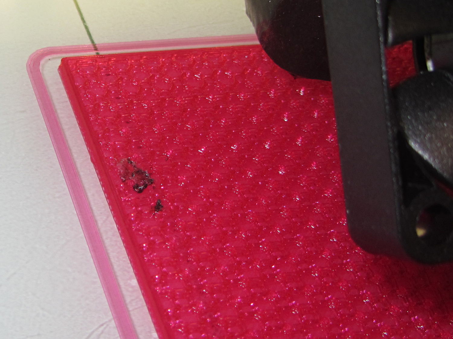
    The small patch of chain mail early in the M2’s PETG conversion had links with four threads along each bar:

    Chain Mail - PETG patches atop PLA patch
    Chain Mail – PETG patches atop PLA patch

    Dropping the bars to 3.3 threads wide produced a slightly smaller patch:

    Chain mail - 6 and 4 thread - detail
    Chain mail – 6 and 4 thread – detail

    The bars on the platform are 1.6 mm = 4 threads wide, because I’ve forced the thread width to 0.40 for that layer:

    Chain Mail - 3.3 wide - Slic3r preview - bottom layer
    Chain Mail – 3.3 wide – Slic3r preview – bottom layer

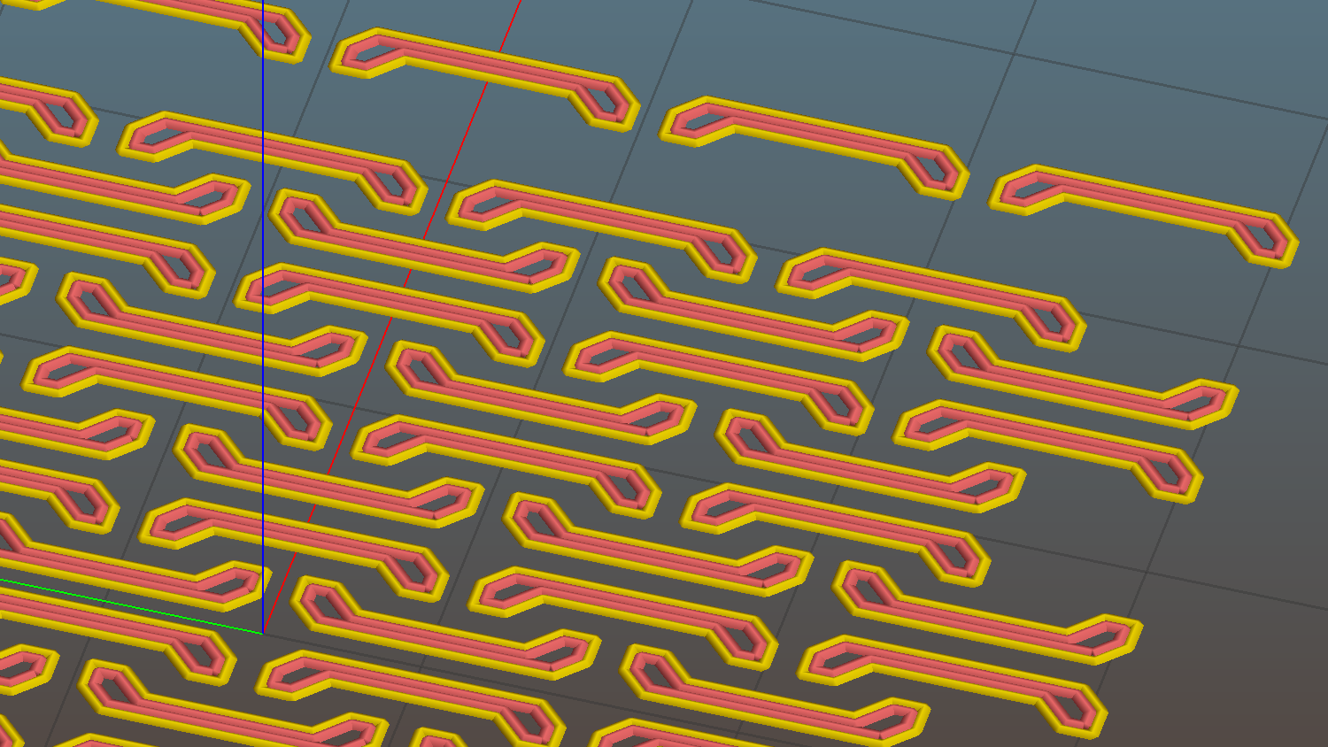
    The remainder are closer to 1.4 mm = 3.3 threads, with the preview showing Slic3r allowed a narrow gap that doesn’t appear in real life:

    Chain Mail - 3.3 wide - Slic3r preview - link bridge layer
    Chain Mail – 3.3 wide – Slic3r preview – link bridge layer

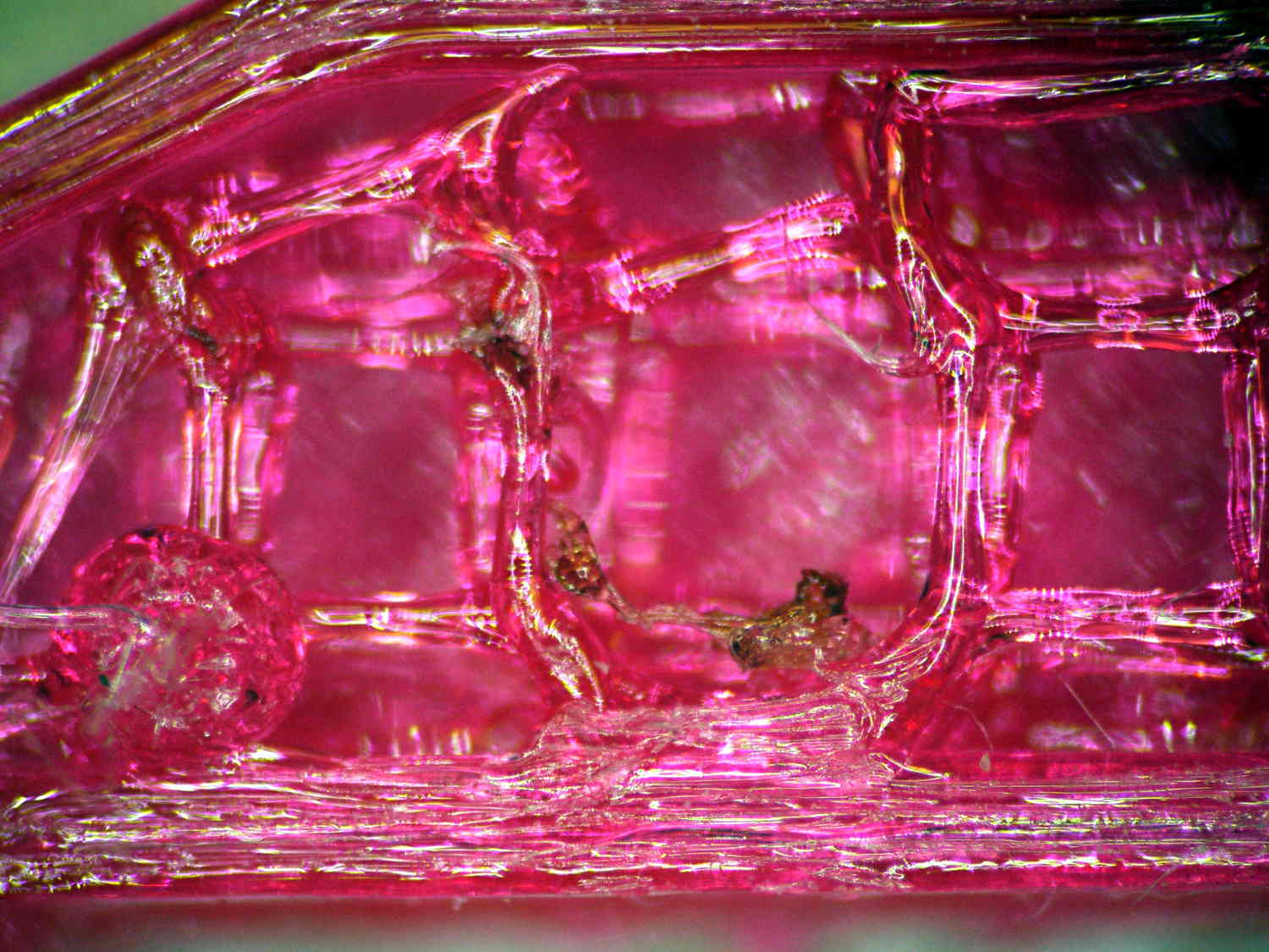
    What’s important about this is that the bridging worked perfectly: all the links emerged free of their neighbors and the patch flexed along both axes.

    Chain mail - 6 and 4 thread
    Chain mail – 6 and 4 thread

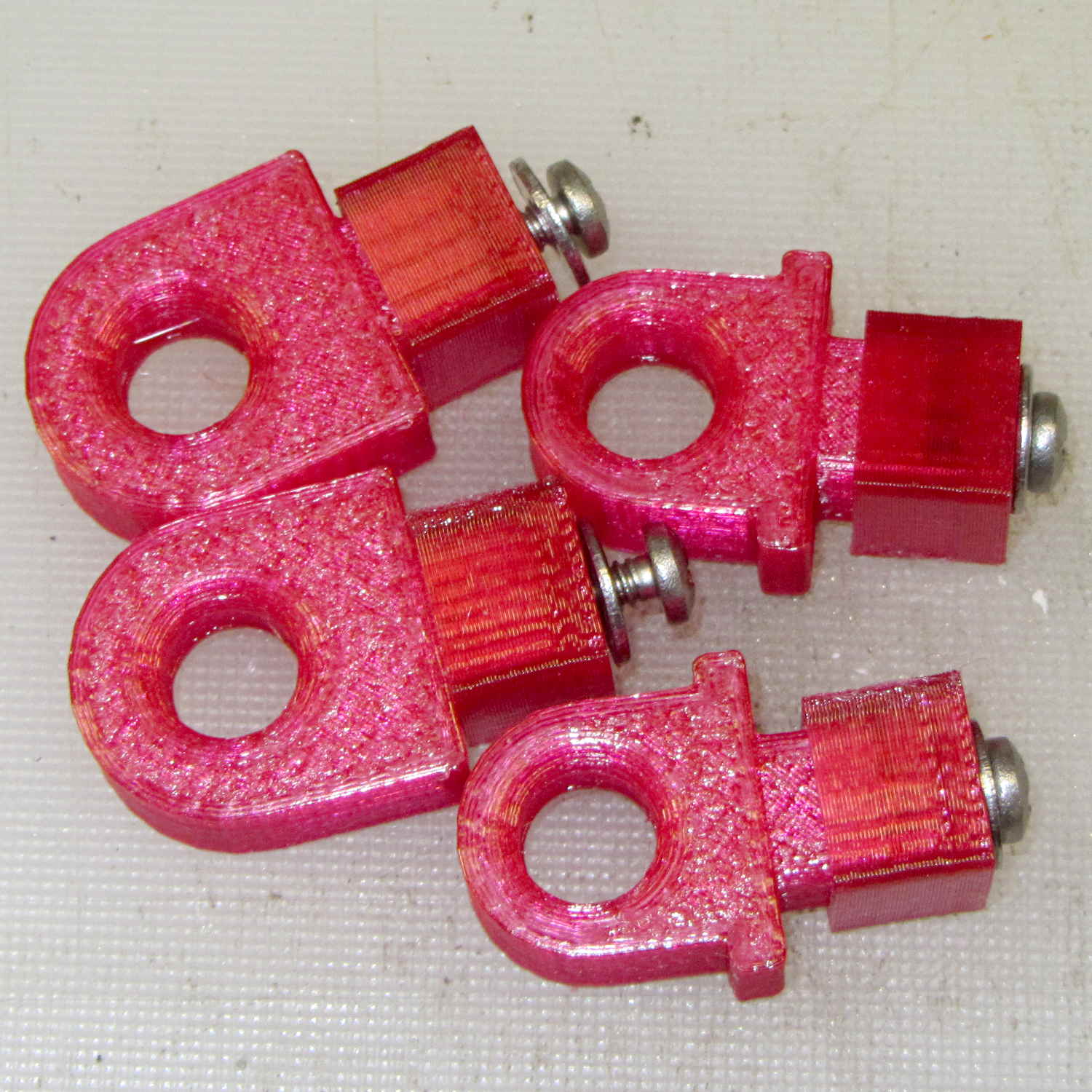
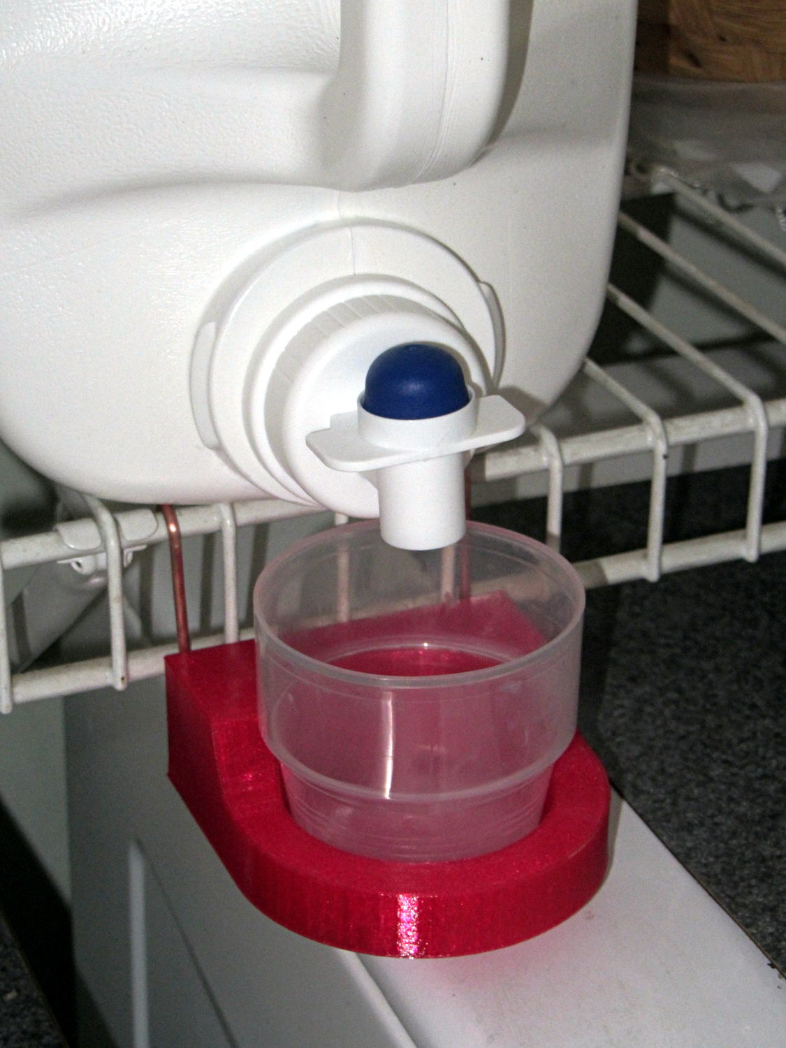
    I tried this on one layer of Elmer’s White Glue, diluted 1:3 with water, and the links bonded firmly. I’d had some trouble with a few links popping off the usual hairspray after the first few layers, so I decided to try something different.

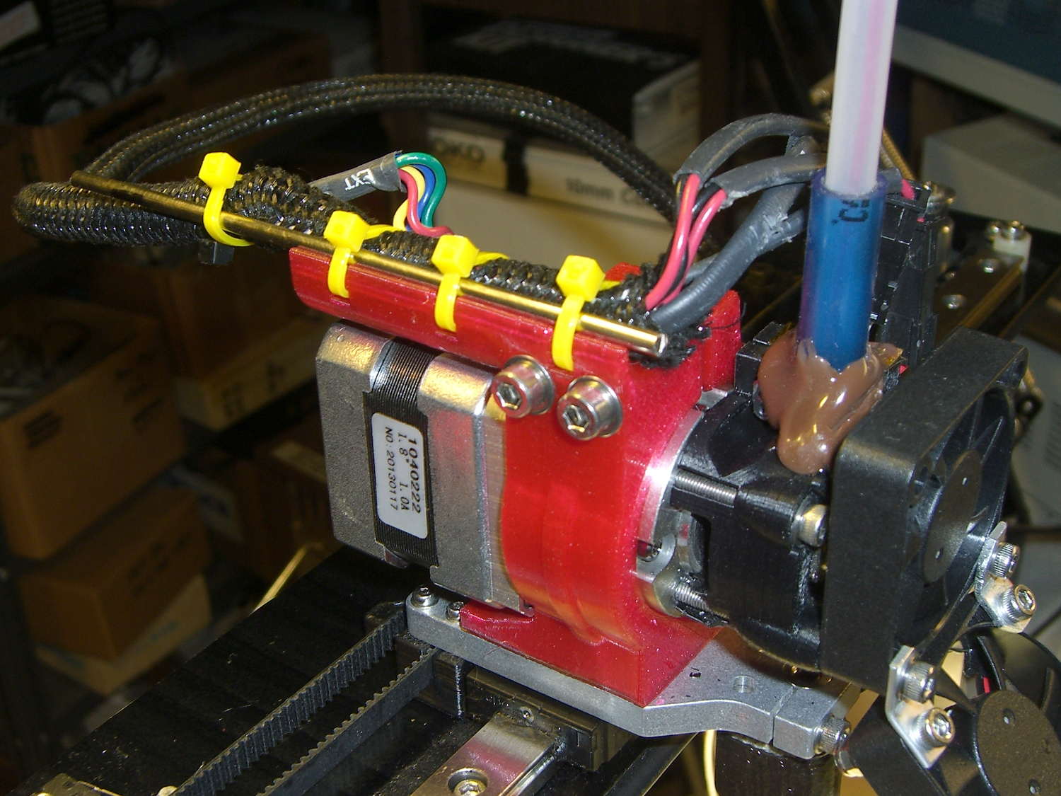
    The fine hair strands have mostly Gone Away, perhaps due to using Concentric infill.

    All in all, PETG looks pretty good, even if it’s just as hard to photograph as red PLA.

    Update: You may prefer the source code as a GitHub gist.

    The OpenSCAD source code:

    // Chain Mail Armor Buttons
    // Ed Nisley KE4ZNU - December 2014
    
    Layout = "Build";			// Link Button LB Joiner Joiners Build PillarMod
    
    //-------
    //- Extrusion parameters must match reality!
    //  Print with 1 shell and 2+2 solid layers
    
    ThreadThick = 0.25;
    ThreadWidth = 0.40;
    
    HoleWindage = 0.2;
    
    Protrusion = 0.1; 				// make holes end cleanly
    
    function IntegerMultiple(Size,Unit) = Unit * ceil(Size / Unit);
    
    //-------
    // Dimensions
    
    //- Set maximum sheet size
    
    SheetSizeX = 55;	// 170 for full sheet on M2
    SheetSizeY = 55;	// 230 ...
    
    //- Diamond or rectangular sheet?
    
    Diamond = false;					// true = rotate 45 degrees, false = 0 degrees for square
    
    BendAround = "X";					// X or Y = maximum flexibility *around* designated axis
    
    Cap = true;										// true = build bridge layers over links
    CapThick = 4 * ThreadThick;						// flat cap on link: >= 3 layers for solid bridging
    
    Armor = true && Cap;							// true = build armor button atop (required) cap
    ArmorThick = IntegerMultiple(2.0,ThreadThick);	// height above cap surface
    
    ArmorSides = 4;
    ArmorAngle = true ? 180/ArmorSides : 0;			// true -> rotate half a side for best alignment
    
    //- Link bar sizes
    
    BarThick = 3 * ThreadThick;
    BarWidth = 3.3 * ThreadWidth;
    
    BarClearance = 4 * ThreadThick;		// vertical clearance above & below bars
    
    VertexHack = 0;						// 0 = no, 1 = slightly reduce openings to avoid coincident vertices
    
    //- Compute link sizes from those values
    
    //- Absolute minimum base link: bar width + corner angle + build clearance around bars
    //  rounded up to multiple of thread width to ensure clean filling
    BaseSide = IntegerMultiple((4*BarWidth + 2*BarWidth/sqrt(2) + 3*(2*ThreadWidth)),ThreadWidth);
    
    BaseHeight = 2*BarThick + BarClearance;           // both bars + clearance
    
    echo(str("BaseSide: ",BaseSide," BaseHeight: ",BaseHeight));
    //echo(str(" Base elements: ",4*BarWidth,", ",2*BarWidth/sqrt(2),", ",3*(2*ThreadWidth)));
    //echo(str(" total: ",(4*BarWidth + 2*BarWidth/sqrt(2) + 3*(2*ThreadWidth))));
    
    BaseOutDiagonal = BaseSide*sqrt(2) - BarWidth;
    BaseInDiagonal = BaseSide*sqrt(2) - 2*(BarWidth/2 + BarWidth*sqrt(2));
    
    echo(str("Outside diagonal: ",BaseOutDiagonal));
    
    //- On-center distance measured along coordinate axis
    //   the links are interlaced, so this is half of what you think it should be...
    
    LinkOC = BaseSide/2 + ThreadWidth;
    
    LinkSpacing = Diamond ? (sqrt(2)*LinkOC) : LinkOC;
    echo(str("Base spacing: ",LinkSpacing));
    
    //- Compute how many links fit in sheet
    
    MinLinksX = ceil((SheetSizeX - (Diamond ? BaseOutDiagonal : BaseSide)) / LinkSpacing);
    MinLinksY = ceil((SheetSizeY - (Diamond ? BaseOutDiagonal : BaseSide)) / LinkSpacing);
    echo(str("MinLinks X: ",MinLinksX," Y: ",MinLinksY));
    
    NumLinksX = ((0 == (MinLinksX % 2)) && !Diamond) ? MinLinksX + 1 : MinLinksX;
    NumLinksY = ((0 == (MinLinksY % 2) && !Diamond)) ? MinLinksY + 1 : MinLinksY;
    echo(str("Links X: ",NumLinksX," Y: ",NumLinksY));
    
    //- Armor button base
    
    ButtonHeight = BaseHeight + BarClearance + CapThick;
    echo(str("ButtonHeight: ",ButtonHeight));
    
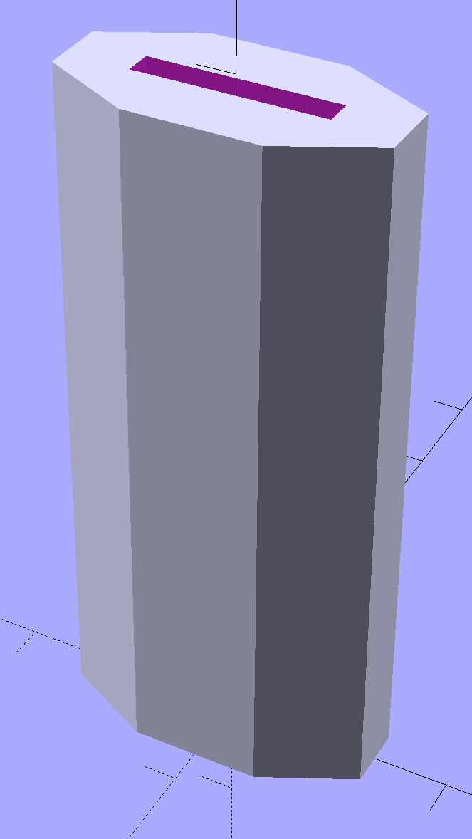
    //- Armor ornament size & shape
    //	 Fine-tune OD & ID to suit the number of sides...
    
    TotalHeight = ButtonHeight + ArmorThick;
    echo(str("Overall Armor Height: ",TotalHeight));
    
    ArmorOD = 1.0 * BaseSide;						// tune for best base fit
    ArmorID = 10 * ThreadWidth;						// make the tip blunt & strong
    
    //-------
    
    module ShowPegGrid(Space = 10.0,Size = 1.0) {
    
      RangeX = floor(95 / Space);
      RangeY = floor(125 / Space);
    
    	for (x=[-RangeX:RangeX])
    	  for (y=[-RangeY:RangeY])
    		translate([x*Space,y*Space,Size/2])
    		  %cube(Size,center=true);
    
    }
    
    
    //-------
    // Create link with armor button as needed
    
    module Link(Topping = false) {
    	
    LinkHeight = (Topping && Cap) ? ButtonHeight : BaseHeight;
    
    render(convexity=3)
    rotate((BendAround == "X") ? 90 : 0)
    	rotate(Diamond ? 45 : 0)
    		union() {
    			difference() {
    				translate([0,0,LinkHeight/2])									// outside shape
    					intersection() {
    						cube([BaseSide,BaseSide,LinkHeight],center=true);
    						rotate(45)
    							cube([BaseOutDiagonal,BaseOutDiagonal,(LinkHeight + 2*Protrusion)],center=true);
    					}
    	
    				translate([0,0,(BaseHeight + BarClearance + 0*ThreadThick - Protrusion)/2])
    					intersection() {											// inside shape
    						cube([(BaseSide - 2*BarWidth),
    								(BaseSide - 2*BarWidth),
    								(BaseHeight + BarClearance + 0*ThreadThick + VertexHack*Protrusion/2)],
    								center=true);
    						rotate(45)
    							cube([BaseInDiagonal,
    									BaseInDiagonal,
    									(BaseHeight + BarClearance + 0*ThreadThick + VertexHack*Protrusion/2)],
    									center=true);
    					}
    
    				translate([0,0,((BarThick + 2*BarClearance)/2 + BarThick)])		// openings for bars
    					cube([(BaseSide - 2*BarWidth - 2*BarWidth/sqrt(2) - VertexHack*Protrusion/2),
    						(2*BaseSide),
    						BarThick + 2*BarClearance - Protrusion],
    						center=true);
    					
    				translate([0,0,(BaseHeight/2 - BarThick)])
    					cube([(2*BaseSide),
    						(BaseSide - 2*BarWidth - 2*BarWidth/sqrt(2) - VertexHack*Protrusion/2),
    						BaseHeight],
    						center=true);
    					
    			}
    
     			if (Topping && Armor)
    				translate([0,0,(ButtonHeight - Protrusion)])		// sink slightly into the cap
    					rotate(ArmorAngle)
    					cylinder(d1=ArmorOD,d2=ArmorID,h=(ArmorThick + Protrusion), $fn=ArmorSides);
    		}
    
    }
    
    
    //-------
    // Create split buttons to join sheets
    
    module Joiner() {
    	
    	translate([-LinkSpacing,0,0])
    		difference() {
    			Link(false);
    			translate([0,0,BarThick + BarClearance + TotalHeight/2 - Protrusion])
    				cube([2*LinkSpacing,2*LinkSpacing,TotalHeight],center=true);
    		}
    		
    	translate([LinkSpacing,0,0])
    		intersection() {
    			translate([0,0,-(BarThick + BarClearance)])
    				Link(true);
    			translate([0,0,TotalHeight/2])
    				cube([2*LinkSpacing,2*LinkSpacing,TotalHeight],center=true);
    		}
    		
    }
    
    
    //-------
    // Build it!
    
    //ShowPegGrid();
    
    if (Layout == "Link") {
    	Link(false);
    }
    
    if (Layout == "Button") {
    	Link(true);
    }
    
    if (Layout == "LB") {
    	color("Brown") Link(true);
    	translate([LinkSpacing,LinkSpacing,0])
    		color("Orange") Link(false);
    }
    
    if (Layout == "Build")
    	for (ix = [0:(NumLinksX - 1)],
    		 iy = [0:(NumLinksY - 1)]) {
    			x = (ix - (NumLinksX - 1)/2)*LinkSpacing;
    			y = (iy - (NumLinksY - 1)/2)*LinkSpacing;
    			translate([x,y,0])
    			color([(ix/(NumLinksX - 1)),(iy/(NumLinksY - 1)),1.0]) 
    				if (Diamond)
    					Link((ix + iy) % 2);					// armor at odd,odd & even,even points
    				else
    					if ((iy % 2) && (ix % 2))				// armor at odd,odd points
                            Link(true);
    					else if (!(iy % 2) && !(ix % 2))		// connectors at even,even points
    						Link(false);
    	}
    
    if (Layout == "Joiner")
    	Joiner();
    
    if (Layout == "Joiners") {
    	NumJoiners = max(MinLinksX,MinLinksY)/2;
    	for (iy = [0:(NumJoiners - 1)]) {
    		y = (iy - (NumJoiners - 1)/2)*2*LinkSpacing + LinkSpacing/2;
    		translate([0,y,0])
    			color([0.5,(iy/(NumJoiners - 1)),1.0]) 
    				Joiner();
    	}
    }
    
    if (Layout == "PillarMod")					// Slic3r modification volume to eliminate pillar infill
    	translate([0,0,(BaseHeight + BarClearance)/2])
    		cube([1.5*SheetSizeX,1.5*SheetSizeY,BaseHeight + BarClearance],center=true);
    
  • MakerGear M2: Slic3r Start G-Code for PETG / V4 / 24 V / Whatever

    The already ponderous chunk of G-Code that slic3r prepends to the outgoing file got a bit more complex with all the changes going on around here.

    As it stands now, the starting G-Code looks like this:

    ;-- Slic3r Start G-Code for M2 starts --
    ;  Ed Nisley KE4NZU - 2015-03-07
    ;  Makergear V4 hot end
    ; Z-min switch at platform, must move nozzle to X=135 to clear
    M140 S[first_layer_bed_temperature]	; start bed heating
    G90				; absolute coordinates
    G21				; millimeters
    M83				; relative extrusion distance
    M17				; enable steppers
    G4 P500			;  ... wait for power up
    G92 Z0			; set Z to zero, wherever it might be now
    G1 Z10 F1000	; move platform downward to clear nozzle; may crash at bottom
    G28 Y0			; home Y to clear plate, origin in middle
    G92 Y-127
    G28 X0			; home X, origin in middle
    G92 X-100
    G1 X130 Y0 F15000	; move off platform to right side, center Y
    G28 Z0			; home Z to platform switch, with measured offset
    G92 Z-2.10
    G0 Z2.0			; get air under switch
    G0 Y-127 F10000	; set up for priming, zig around corner
    G0 X0			;  center X
    G0 Y-125.0		; just over platform edge
    G0 Z0 F500	; exactly at platform
    M109 S[first_layer_temperature]	; set extruder temperature and wait
    M190 S[first_layer_bed_temperature]	; wait for bed to finish heating
    G1 E20 F300		; prime to get pressure, generate blob on edge
    G0 Y-123 F500		; shear off blob
    G1 X15 F15000	; jerk away from blob, move over surface
    G4 P500			; pause to attach
    G1 X45 F500		; slowly smear snot to clear nozzle
    G1 Z1.0 F2000	; clear bed for travel
    ;-- Slic3r Start G-Code ends --
    

    The blow-by-blow description…

    Lines 9-10: Manually enable stepper drivers and wait half a second

    Changing to a 24 V power supply for the motors doesn’t affect the winding current (because the drivers control that), but it does increase the current’s rate-of-change (because inductor voltage = L di/dt and the applied voltage is 26% higher) during each microstep. That means the motors snap to a whole-step position a bit faster when the Marlin firmware enables the drivers and the higher di/dt induces more glitch voltage in, say, the endstop cable, triggering a false contact sense (as the circuit depends on the Arduino’s 20+ kΩ internal pullup resistor). In any event, a half-second snooze avoids the problem.

    Lines 18-19: Home Z-axis & set platform switch offset

    The only way to set the offset accurately is to compare the actual height of a printed object (or the skirt around it) with the nominal value. I use 5 mm tall thinwall open boxes and, after setting the Extrusion Multiplier properly, they’re good test objects.

    Lines 22-24: Extruder final heating

    PETG tends to stick to the nozzle, so the nozzle now sits just over the edge of the glass plate and flush with the top surface, so that the initial drool forms a glob anchored to the side of the plate. It looks like this:

    V4 PETG - preheat position
    V4 PETG – preheat position

    Notice the curl attached to the nozzle: I generally pick those off with a tweezer, but let this one remain to show how this mess works.

    Line 31: Prime the extruder

    With the hot end and platform temperatures stabilized, I ram 20 mm of filament into the extruder to refill it and stabilize its internal pressure. Because it’s been drooling ever since the plastic melted, not very much plastic comes out, but what does emerge enlarges the blob and bonds with the plastic stuck on the nozzle, thusly:

    V4 PETG - extruder priming
    V4 PETG – extruder priming

    Lines 28-29: Detach the blob

    Moving 2 mm onto the platform leaves most of the snot hanging on the edge of the glass, with just a bit on the far side of the nozzle. Doing that relatively slowly gives the plastic time to flow around the nozzle and remain with the blob, then zipping to X=15 encourages it to detach.

    Lines 30-31: Wipe away what’s left

    Pause for half a second to allow whatever’s left to attach to the platform, then slowly move to X=45, and watch the remaining snot leave a trail on the platform as it oozes off the nozzle.

    Then hop up 1 mm to clear the platform and pass control to the rest of the G-Code with a clean nozzle!

    That’s the ideal outcome, of course. Sometimes a recalcitrant blob hangs on, but it generally oozes off while the nozzle trudges around three skirt outlines…

  • Calibration Boxes for 3D Printing

    The OpenSCAD script now produces either a thinwall open box or a solid box with the same outside shape and dimensions:

    The rounded corners prevent edge glitches from throwing off the measurement, plus they verify that small segments print properly.

    lengthy writeup on why I like the thinwall open box so much may be more than you want to know on the subject. Just do it, OK?

    The solid box lets you check the outside dimensions (20 x 20 x 5 mm) and the slicer’s infill parameters.

    The first few attempts with a new setup won’t look very good, but that’s the whole point:

    M2 V4 Calibration Objects
    M2 V4 Calibration Objects

    Getting a workable profile and accurate Z-axis setting required maybe a dozen quick prints & parameter changes. After that, they’re good for verifying that any change you make hasn’t screwed up something beyond recovery.

    Put five of them on the platform to verify overall alignment (“leveling”) and first-layer thickness:

    Thinwall Calibration Cubes - 5 copies
    Thinwall Calibration Cubes – 5 copies

    A few iterations will generate plenty of show-n-tell tchotchkes:

    Thinwall open boxes from platform leveling
    Thinwall open boxes from platform leveling

    As nearly as I can tell, if you can’t print these reliably, there’s no point in trying to print anything else.

    Even better, when you suddenly can’t print anything else reliably, these simple boxes will tell you what’s gone wrong…

    [Update: The revised version works better.]

    The OpenSCAD source code:

    // Calibration boxes
    //  Thin wall open box - set Extrusion Multiplier
    //  Solid box - verify infill settings
    // Ed Nisley - KE4ZNU - 2015-03
    
    Layout = "Open";					// Open Solid
    
    //-------
    //- Extrusion parameters must match reality!
    
    ThreadThick = 0.25;
    ThreadWidth = 0.40;
    
    Protrusion = 0.1;           // make holes end cleanly
    
    function IntegerMultiple(Size,Unit) = Unit * ceil(Size / Unit);
    
    //-------
    // Dimensions
    
    Height = IntegerMultiple(5.0,ThreadThick);
    
    WallThick = 1*ThreadWidth;
    
    CornerRadius = 2.0;
    CornerSides = 4*8;
    
    SideLen = 20.0 - 2*CornerRadius;
    
    Rotation = 45;
    
    //-------
    
    module ShowPegGrid(Space = 10.0,Size = 1.0) {
    
      Range = floor(50 / Space);
    
        for (x=[-Range:Range])
          for (y=[-Range:Range])
            translate([x*Space,y*Space,Size/2])
              %cube(Size,center=true);
    }
    
    //--------
    
    module Solid() {
    	hull() {
    		for (i=[-1,1], j=[-1,1])
    			translate([i*SideLen/2,j*SideLen/2,0])
    				cylinder(r=CornerRadius,h=Height,$fn=CornerSides);
    	}
    }
    
    module Thinwall() {
    	difference() {
    		Solid();
    		hull() {
    			for (i=[-1,1], j=[-1,1])
    				translate([i*SideLen/2,j*SideLen/2,-Protrusion])
    					cylinder(r=(CornerRadius - WallThick),h=(Height + 2*Protrusion),$fn=CornerSides);
    		}
    	}
    }
    
    //-------
    
    //ShowPegGrid();
    
    rotate(Rotation)
    	if (Layout == "Open")
    		Thinwall();
    	else
    		Solid();
    
  • MakerGear M2: PETG Motor Mount

    The M2’s extruder motor mounts in a printed holder that attaches to the X-axis linear rail. The wire guide on the original holder snapped when I installed it, with the fractured end showing poor infill and bonding, but the rest of the mount held together and, my initial misgivings notwithstanding, I never had much motivation to print a replacement. With the PETG settings working pretty well, I fetched the updated STL file, oriented it for printing, and ran off a motor mount:

    M2 Motor Mount - PETG on platform
    M2 Motor Mount – PETG on platform

    That’s at 40% 3D Honeycomb infill, three perimeters and three top/bottom layers, which seems plenty strong enough for the purpose: I can’t bend the wire guide at all, no how, no way!

    Despite a few hairs, the nozzle didn’t deposit any boogers. Things are looking up…

    A cap should fit over the cable guide, presumably for neatness, but I didn’t see much point in that. Instead, I added a steel rod to support the loom and provide some strain relief beyond the end of the guide, as the wires want to flex at that spot:

    M2 Motor Mount - PETG installed - cable brace
    M2 Motor Mount – PETG installed – cable brace

    Because the V4 hot end mounts to that aluminum plate, rather than the filament drive, the whole operation didn’t disturb the nozzle position at all. Whew!

  • Sienna Hood Rod Pivot: PETG Edition

    Our Larval Engineer reports that the PLA pivot for the Sienna’s hood rod didn’t survive contact with the van’s NYS Inspection. I’m not surprised, as PLA tends to be brittle and the inspection happened on a typical February day in upstate New York. Seeing as how PETG claims to be stronger and more durable than PLA, I ran off some replacements:

    Toyota Sienna hood rod pivot - small - PETG
    Toyota Sienna hood rod pivot – small – PETG

    The square cap fit snugly over the bottom of the post; PETG tolerances seem pretty much the same as for PLA.

    A slightly larger loop may be more durable, so I changed one parameter in the OpenSCAD code to get this:

    Toyota Sienna Hood Rod Pivot - up-armored - solid model
    Toyota Sienna Hood Rod Pivot – up-armored – solid model

    Which printed just like you’d expect:

    Toyota Sienna hood rod pivot - large - PETG hairs
    Toyota Sienna hood rod pivot – large – PETG hairs

    Despite the hairs stretching between each part, the nozzle didn’t deposit any boogers during the print. The top and bottom use Hilbert Curve infill, which looks pretty and keeps the nozzle from zipping back and forth quite so much; perhaps that’s a step in the right direction.

    Tapping the holes for 6-32 stainless machines screws went easily enough:

    Toyota Sienna hood rod pivot - PETG - assembled
    Toyota Sienna hood rod pivot – PETG – assembled

    She gets one of each and I keep the others for show-n-tell sessions.

    The OpenSCAD source code, which differs from the original by a constant or two:

    // Sienna Hood Rod Pivot
    // Ed Nisley KE4ZNU November 2013
    
    //- Extrusion parameters must match reality!
    //  Print with 2 shells and 3 solid layers
    
    ThreadThick = 0.25;
    ThreadWidth = 0.40;
    
    HoleWindage = 0.2;
    
    Protrusion = 0.1;			// make holes end cleanly
    
    inch = 25.4;
    
    function IntegerMultiple(Size,Unit) = Unit * ceil(Size / Unit);
    
    //----------------------
    // Dimensions
    
    ShellOD = 20.0;
    ShellID = 8.75;
    ShellLength = 10.0;
    
    TaperLength = 1.5;
    TaperID = 11.4;
    
    BaseWidth = 20.0;
    BaseThick = 3.0;
    
    PegSide = 9.5;					// mounting peg through sheet metal
    PegLength = 7.0;
    PegCornerTrim = 0.75;
    PegHoleOD = 0.107*inch;			//  6-32 tap hole
    
    PegTrimSide = sqrt(2)*PegSide - PegCornerTrim;
    
    ClampWall = 3.0;				// clamping cap under sheet metal
    ClampHoleOD = 0.150*inch;		//  6-32 clearance hole
    ClampCap = 3.0;					// solid end thickness
    
    PanelThick = 2.0;				// sheet metal under hood
    
    NumSides = 6*4;
    
    //----------------------
    // Useful routines
    
    module PolyCyl(Dia,Height,ForceSides=0) {			// based on nophead's polyholes
    
      Sides = (ForceSides != 0) ? ForceSides : (ceil(Dia) + 2);
    
      FixDia = Dia / cos(180/Sides);
    
      cylinder(r=(FixDia + HoleWindage)/2,
               h=Height,
    	   $fn=Sides);
    }
    
    module ShowPegGrid(Space = 10.0,Size = 1.0) {
    
      Range = floor(50 / Space);
    
    	for (x=[-Range:Range])
    	  for (y=[-Range:Range])
    		translate([x*Space,y*Space,Size/2])
    		  %cube(Size,center=true);
    
    }
    
    //----------------------
    // Build it
    
    //ShowPegGrid();
    
    // pivot
    
    translate([-ShellOD,0,0])
    	difference() {
    		union() {
    			cylinder(r=ShellOD/2,h=ShellLength,$fn=NumSides);		// housing
    			translate([-ShellOD/2,0,0])								// filler
    				cube([ShellOD,(ShellOD/2 + BaseThick),ShellLength],center=false);
    			translate([0,(ShellOD/2 + BaseThick/2),ShellLength/2])	// foot
    				cube([BaseWidth,BaseThick,ShellLength],center=true);
    
    			translate([0,											// peg
    						(ShellOD/2 + PegLength/2 + BaseThick - Protrusion),
    						PegSide/2])
    				intersection() {
    					cube([PegSide,(PegLength + Protrusion),PegSide],center=true);
    					rotate([0,45,0])
    						cube([PegTrimSide,2*PegLength,PegTrimSide],center=true);
    				}
    		}
    
    		PolyCyl(ShellID,ShellLength,NumSides);		// central hole
    
    		translate([0,0,-Protrusion])				// end bevels
    			cylinder(r1=TaperID/2,r2=ShellID/2,h=(TaperLength + Protrusion),$fn=NumSides);
    		translate([0,0,(ShellLength + Protrusion)])
    			rotate([180,0,0])
    				cylinder(r1=TaperID/2,r2=ShellID/2,h=(TaperLength + Protrusion),$fn=NumSides);
    
    		translate([0,0,PegSide/2])					// screw tap hole
    			rotate([-90,0,0])
    				PolyCyl(PegHoleOD,(ShellOD + BaseThick + PegLength),6);
    
    	}
    
    // anchor cap
    
    translate([2*PegSide,0,0])
    	difference() {
    		translate([0,0,(PegLength + ClampCap)/2])					// overall shape
    			cube([(PegSide + ClampWall),(PegSide + ClampWall),(PegLength + ClampCap)],center=true);
    		translate([0,0,(PegLength/2 + ClampCap + Protrusion)])		// peg cutout
    			cube([(PegSide + ThreadWidth),(PegSide + ThreadWidth),(PegLength + Protrusion)],center=true);
    		translate([0,0,-Protrusion])								// screw clearance
    				PolyCyl(ClampHoleOD,2*PegLength,6);
    	}
    
  • Build Platform Chisel Handle

    My father used a little chisel for some unknown purpose while he was an instrument repair tech at Olmstead AFB during the mid-60s. Its homebrew wood handle eventually disintegrated and I made a quick-and-truly-dirty replacement from epoxy putty and heatshrink tubing, promising that I’d eventually do better.

    Seeing as how I use it to pop objects off the M2’s build platform and being in need of a tall, skinny object to see how PETG works with towers, that chisel now has a nice magenta handle:

    Platform Chisel - PETG handle
    Platform Chisel – PETG handle

    Well, OK, it may not be the prettiest handle you’ve ever seen, but it’s much better than an epoxy turd, as measured along several axes.

    Incidentally, epoxy putty bonds to clean steel like there’s no tomorrow. I had to file the last remaining chunks off and sandpaper the residue down to clean steel again.

    The solid model shows it in build-a-tower mode:

    Chisel Handle - solid model
    Chisel Handle – solid model

    I think at least one rounded end would improve its appearance. Two rounded ends would make it un-printable in that orientation, although a low-vertex polygonal approximation might have enough of a flat bottom to suffice. Given how long it took me to replace the epoxy, that could take a while.

    The central slot fits snugly around the handle, requiring persuasion from a plastic mallet to set in in position.

    Once again, the nozzle shed a small brown PETG booger after the first few layers:

    PETG Chisel Handle - oxidized plastic
    PETG Chisel Handle – oxidized plastic

    I’m beginning to think PETG infill needs more attention than I’ve been giving it: that’s 15% 3D Honeycomb combined over three layers.

    The OpenSCAD source code:

    // Chisel Handle
    // Ed Nisley KE4ZNU - March 2015
    
    Layout = "Show";			// Show Build
    
    //-------
    //- Extrusion parameters must match reality!
    
    ThreadThick = 0.25;
    ThreadWidth = 0.40;
    
    HoleWindage = 0.2;
    
    Protrusion = 0.1; 				// make holes end cleanly
    
    function IntegerMultiple(Size,Unit) = Unit * ceil(Size / Unit);
    
    //-------
    // Dimensions
    
    Shank = [16.0,2.4,59];			// width, thickness, length to arched end
    
    BladeWidth = 27.0;
    
    HandleSides = 8;
    
    //-------
    
    module ShowPegGrid(Space = 10.0,Size = 1.0) {
    
      RangeX = floor(95 / Space);
      RangeY = floor(125 / Space);
    
    	for (x=[-RangeX:RangeX])
    	  for (y=[-RangeY:RangeY])
    		translate([x*Space,y*Space,Size/2])
    		  %cube(Size,center=true);
    
    }
    
    module PolyCyl(Dia,Height,ForceSides=0) {			// based on nophead's polyholes
      Sides = (ForceSides != 0) ? ForceSides : (ceil(Dia) + 2);
      FixDia = Dia / cos(180/Sides);
      cylinder(r=(FixDia + HoleWindage)/2,h=Height,$fn=Sides);
    }


    module Handle() {
    	difference() {
    		scale([1.0,0.5,1.0])
    			rotate(180/HandleSides)
    				cylinder(d=BladeWidth/cos(180/HandleSides),h=Shank[2],$fn=HandleSides);
    		translate([0,0,Shank[2]/2])
    			cube(Shank + [0,0,2*Protrusion],center=true);
    	}
    }
    
    //-------
    // Build it!
    
    //ShowPegGrid();
    
    if (Layout == "Show") {
    	Handle();
    }
    
    if (Layout == "Build") {
    	translate([0,0,0])
    		rotate([0,0,0])
    			Handle();
    }
    
  • Detergent Cap Holder

    Although chain mail provides a good test of the M2’s setup and slicing parameters, it doesn’t offer much in the way of infill. To test that, I designed a holder for the cap of the bulk laundry detergent container:

    Detergent Cap Holder - in place
    Detergent Cap Holder – in place

    The container must rest on its side, but if you snap the cap back in place, detergent will ooze out between the cap and the container and drip on whatever’s below. The never-sufficiently-to-be-damned Whirlpool high-efficiency front loading washer vibrates like crazy during the spin cycle, shaking anything from its top to the floor. The cap must sit in a cup to catch the inevitable ooze down its side, the wire shelf already has a bunch of other crap on it, and I needed a bulky test object, soooo ….

    We regard that detergent container and its cap as a botched design.

    Anyhow.

    The holder has pair of holes in its back surface for the copper (!) hangers:

    Detergent Cap Holder - solid model - rear
    Detergent Cap Holder – solid model – rear

    I stripped a length of 10 AWG wire, straightened & annealed it, bent up a pair of hooks, then hammered them just flat enough to work-harden the copper, and they were all good.

    Printing that massive block with 20% infill showed that the nozzle collected enough PETG during the first few layers to leave a substantial booger behind:

    Detergent cup holder - oxidized PETG
    Detergent cup holder – oxidized PETG

    Fortunately, that was the only one and it ended up on the inside, tucked out of sight.

    The PETG deposit on the outside of the nozzle gradually darkens from the original magenta to brown, which I’m pretty sure means that it’s oxidizing / decomposing / going bad. There’s no obvious way to remove the booger during the print; I’ve taken to wiping the nozzle after each object, while it’s still hot and the PETG remains flexible.

    Because the nozzle didn’t accumulate any more PETG during the rest of the print, it’s not a constant problem, but I have seen boogers several times so far.

    Perhaps continued refinement of the slicing parameters will help? One can always hope…

    The OpenSCAD source code:

    // Detergent Cap Holder
    // Ed Nisley KE4ZNU - March 2015
    
    Layout = "Show";			// Show Build
    
    //-------
    //- Extrusion parameters must match reality!
    
    ThreadThick = 0.20;
    ThreadWidth = 0.40;
    
    HoleWindage = 0.2;
    
    Protrusion = 0.1; 				// make holes end cleanly
    
    function IntegerMultiple(Size,Unit) = Unit * ceil(Size / Unit);
    
    //-------
    // Dimensions
    
    RecessX = 45.0;								// cap recess
    RecessDia = 55.0;
    RecessDepth = 10.0;
    RecessSides = 16*4;
    
    BaseThick = 5.0;							// block thickness below cap
    
    PinDia = 2.5;
    PinLength = 20.0;
    PinOC = 65.0;
    PinInset = 7.0;
    PinZ = BaseThick;
    
    Block = [RecessX,PinOC + 2*PinInset,30.0];	// overall block size (X to cap center)
    
    FairingRadius = Block[2] - RecessDepth - BaseThick;
    
    //-------
    
    module ShowPegGrid(Space = 10.0,Size = 1.0) {
    
      RangeX = floor(95 / Space);
      RangeY = floor(125 / Space);
    
    	for (x=[-RangeX:RangeX])
    	  for (y=[-RangeY:RangeY])
    		translate([x*Space,y*Space,Size/2])
    		  %cube(Size,center=true);
    
    }
    
    module PolyCyl(Dia,Height,ForceSides=0) {			// based on nophead's polyholes
      Sides = (ForceSides != 0) ? ForceSides : (ceil(Dia) + 2);
      FixDia = Dia / cos(180/Sides);
      cylinder(r=(FixDia + HoleWindage)/2,h=Height,$fn=Sides);
    }
    
    module Holder() {
    	difference() {
    		union() {									// main shape
    			translate([-Block[0]/2,0,Block[2]/2])
    			cube(Block,center=true);
    			cylinder(d=Block[1],h=Block[2],$fn=RecessSides);
    		}
    		for (j=[-1,1])								// mounting pin holes
    			translate([-(Block[0] + Protrusion),j*PinOC/2,PinZ])
    				rotate([0,90,0]) rotate(180/6)
    					PolyCyl(PinDia,PinLength + Protrusion,6);
    		translate([0,0,Block[2]])					// fairing arc
    			rotate([90,0,0])
    				cylinder(r=FairingRadius,h=2*Block[1],center=true);
    		translate([Block[0]/2,0,Block[2]/2 + RecessDepth + BaseThick])	// flat top
    			scale([1,2,1])
    				cube(Block,center=true);
    		translate([0,0,BaseThick])
    			cylinder(d1=RecessDia,d2=1.1*RecessDia,h=Block[2]);
    	}
    }
    
    //-------
    // Build it!
    
    //ShowPegGrid();
    
    if (Layout == "Show") {
    	Holder();
    }
    
    if (Layout == "Build") {
    	translate([0,0,0])
    	rotate([0,0,0])
    	Holder();
    }