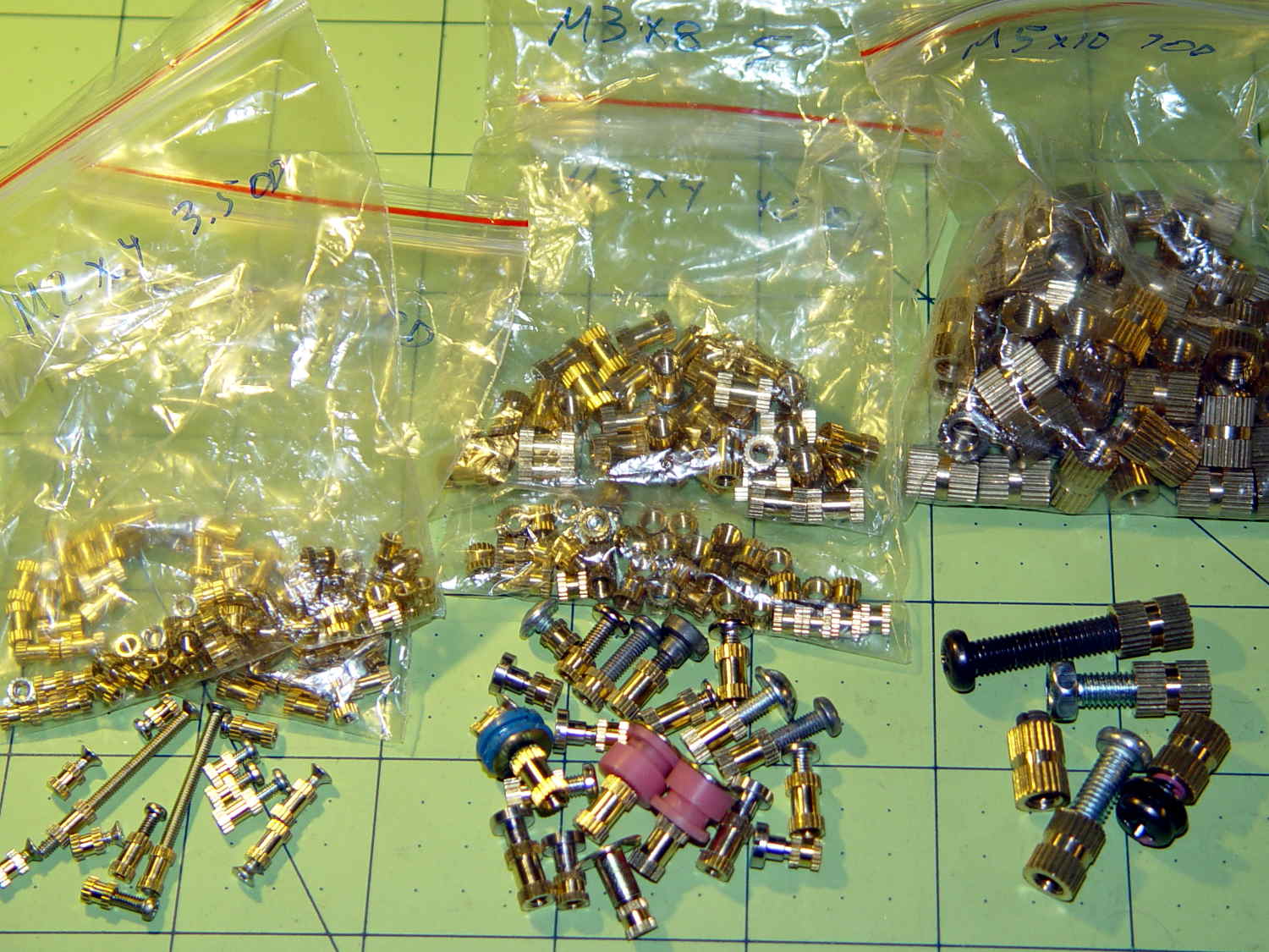
Even vacuum tubes destined to be decorations need sockets:
They’re entirely plastic, of course, but they match the dimensions of “real” tube sockets pretty closely. The bosses around the pins have hard-inch dimensions, so you (well, I) can unleash Genuine Greenlee Radio Chassis Punches on sheet metal.
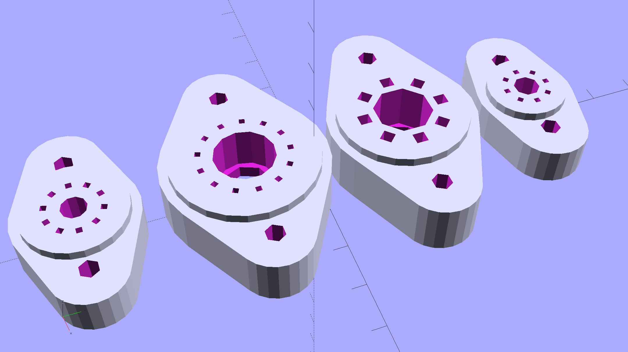
All the key dimensions come from a table, so you can build whatever sockets you need. These four seem to cover the most common relics of the Hollow State Empire:
T_NAME = 0;                                             // common name
T_NUMPINS = 1;                                          // total, with no allowance for keying
T_PINBCD = 2;                                           // tube pin circle diameter
T_PINOD = 3;                                            //  ... diameter
T_PINLEN = 4;                                           //  ... length (overestimate)
T_HOLEOD = 5;                                           // nominal panel hole from various sources
T_PUNCHOD = 6;                                          // panel hole optimized for inch-size Greenlee punches
T_TUBEOD = 7;                                           // envelope or base diameter
T_PIPEOD = 8;                                           // light pipe from LED to tube base
T_SCREWOC = 9;                                          // mounting screw holes

//    Name      pins     BCD   dia  length   hole            punch       env  pipe screw
TubeData = [
    ["Mini7",     8,    9.53, 1.016,   7.0,  16.0,        11/16 * inch,  18.0,  5.0, 22.5],
    ["Octal",     8,   17.45, 2.36,   10.0,  36.2,    (8 + 1)/8 * inch,  32.0, 11.5, 39.0],
    ["Noval",    10,   11.89, 1.1016,  7.0,  22.0,          7/8 * inch,  21.0,  5.0, 28.0],
    ["Duodecar", 13,   19.10, 1.05,    9.0,  32.0,         1.25 * inch,  38.0, 12.5, 39.0],
];
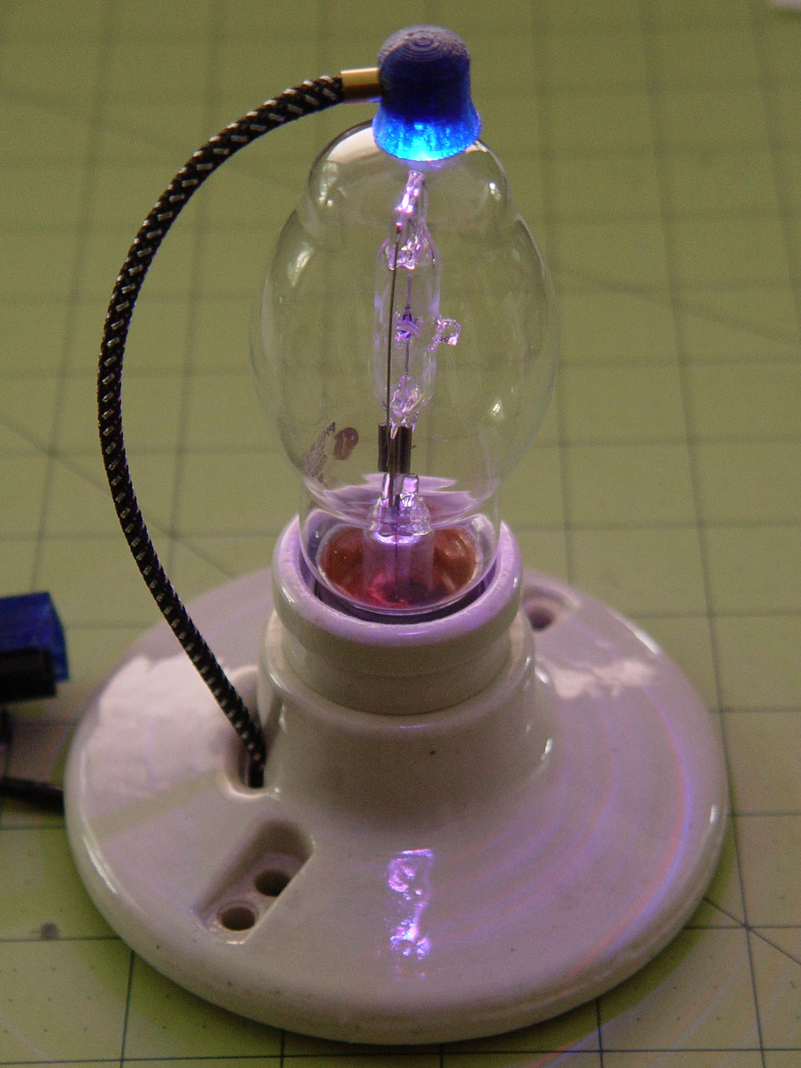
Given that the tubes lack electrical connections, I omitted the base keying: plug them in for best visual effect.
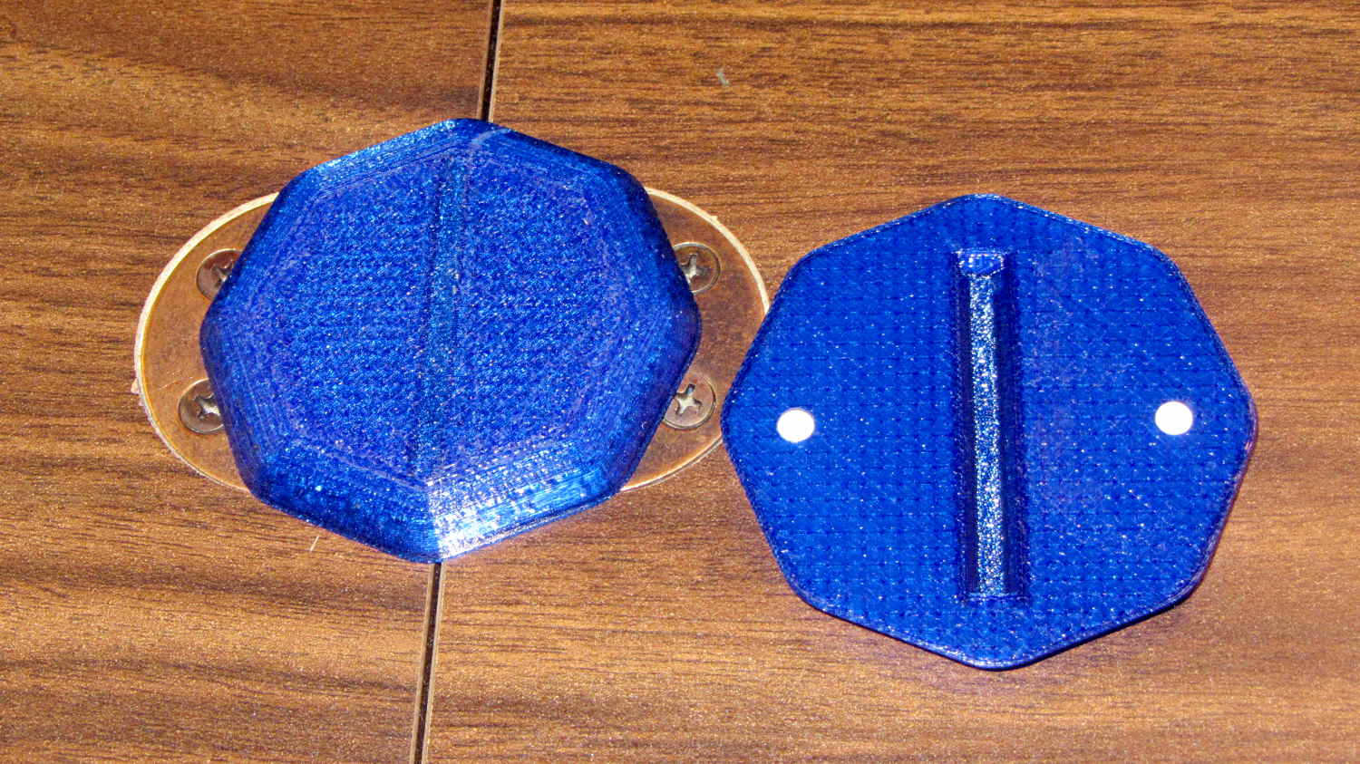
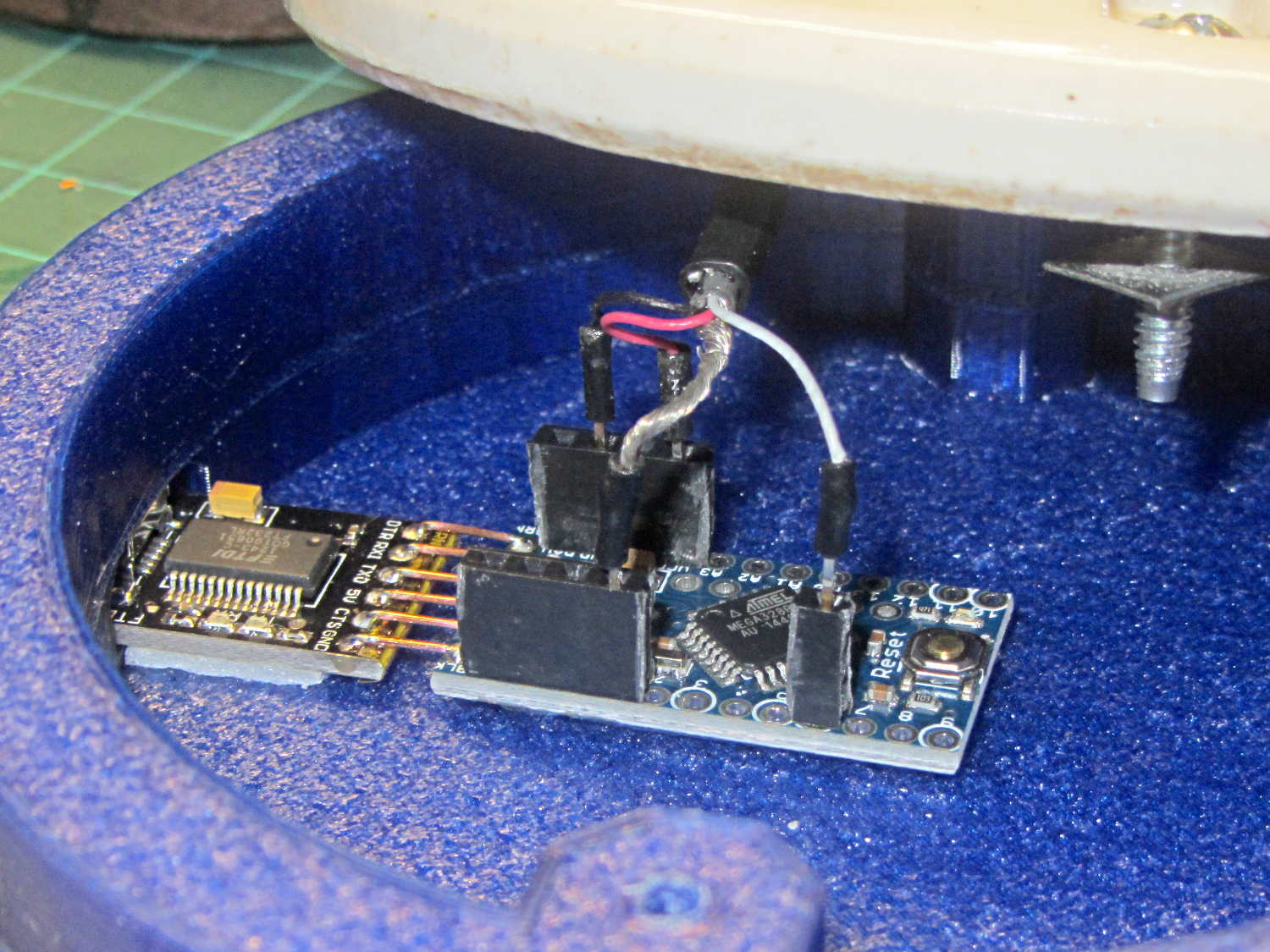
The hole through the middle passes light from a knockoff Neopixel on a 10 mm OD PCB:
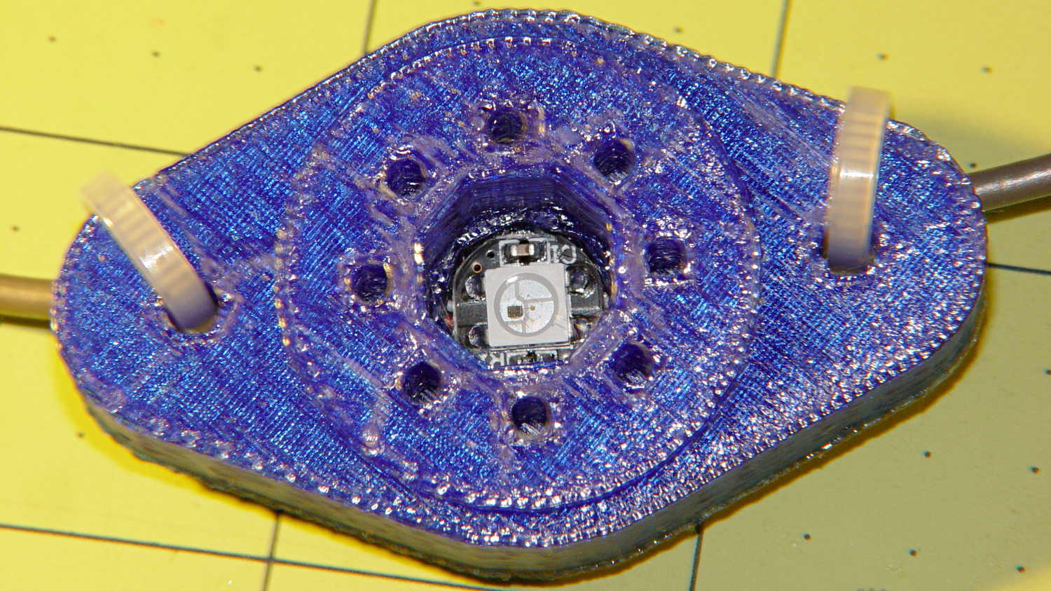
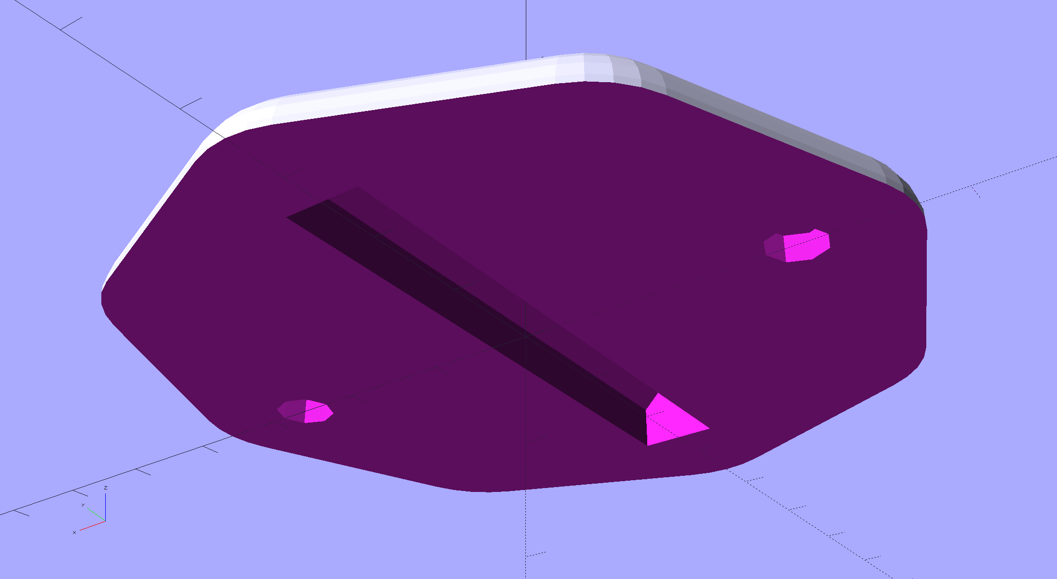
Seen from the bottom, each base traps a pair of 6-32 nuts for chassis mounting and has a Neopixel press-fit in the middle:

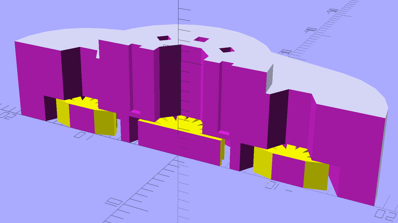
Those recesses require support structures:

The Miniature 7-pin socket has the least space for the 10 mm OD Neopixel PCB and shows the thin layer between the bottom of the pin holes and the top of the openings.
You see half of the eight holes in the “7 pin” socket, because it has the eighth hole where a standard socket has a gap between pins 1 and 7.
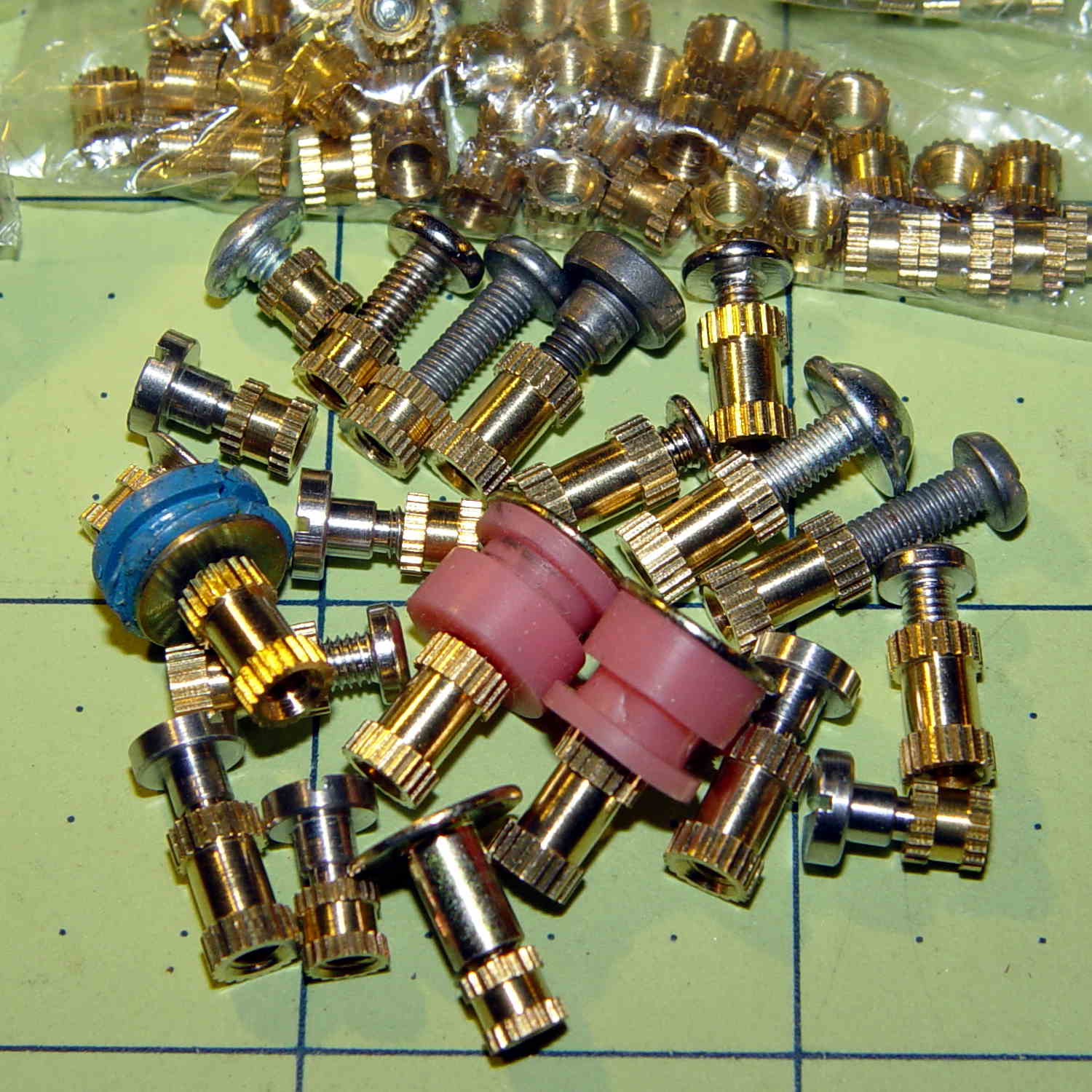
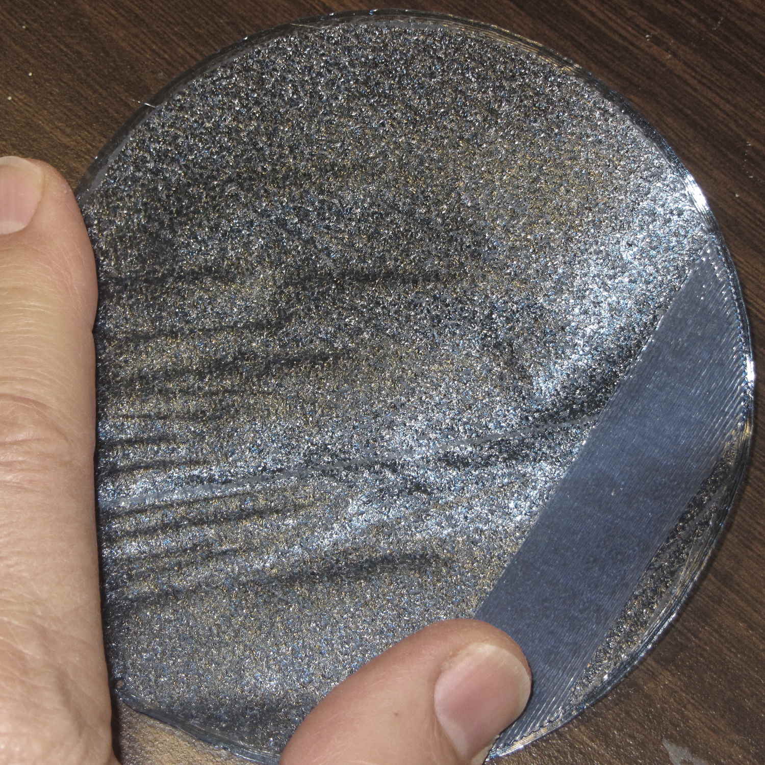
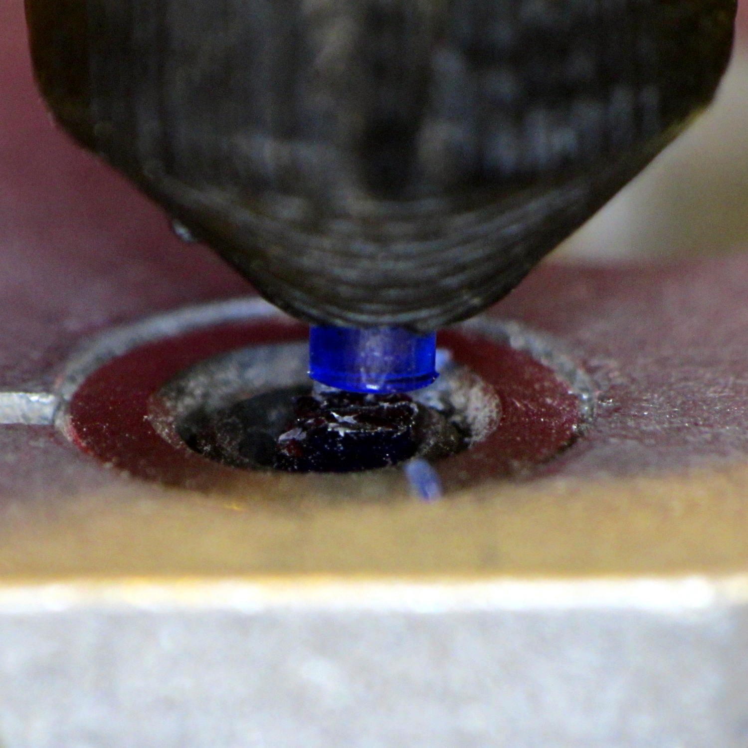
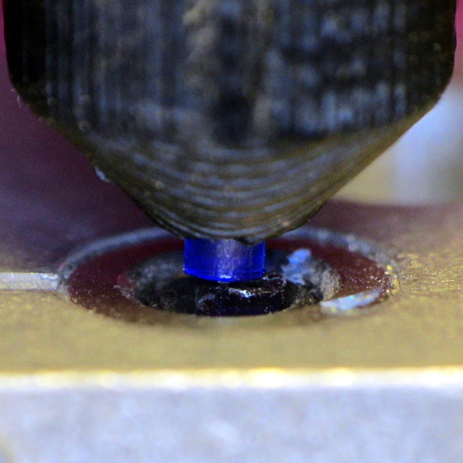
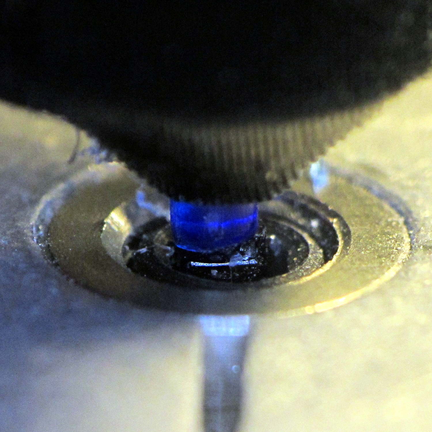
Somewhat to my surprise, punching the support spiders out with a 6-32 stud (grabbed in the drill press) worked perfectly:
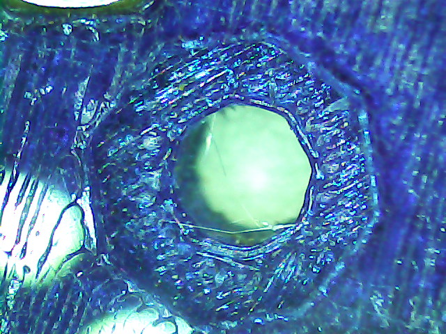
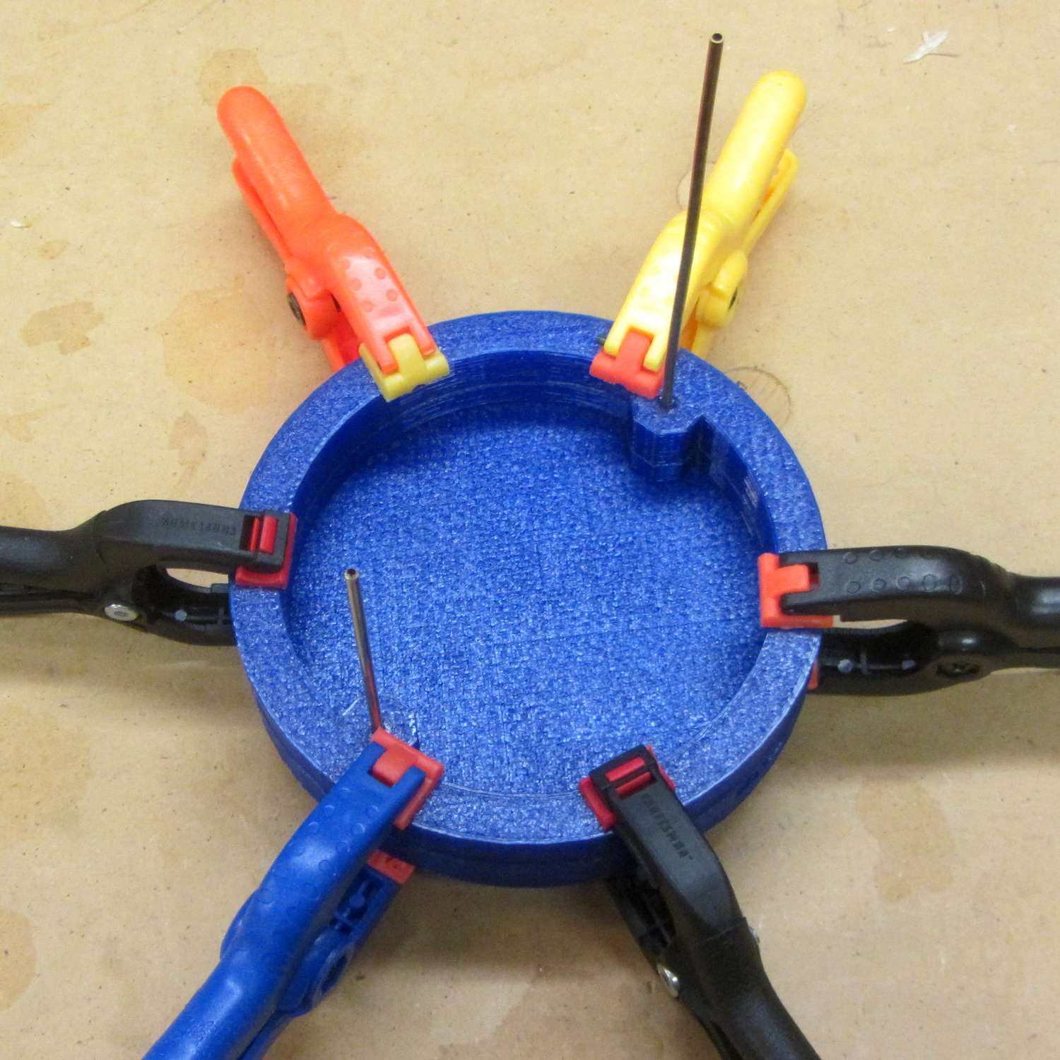
They look like I intended to build tiny decorations:
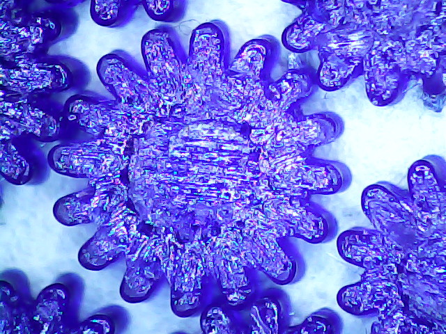
The cookies held on tenuously, then released with a loud bang! as I gradually increased the pressure. A PETG support structure in a blind recess wouldn’t pop out nearly so well.
The OpenSCAD source code as a GitHub gist:
| // Vacuum Tube LED Lights | |
| // Ed Nisley KE4ZNU January 2016 | |
| Layout = "Sockets"; // Cap LampBase USBPort Socket(s) | |
| Section = true; // cross-section the object | |
| Support = true; | |
| //- Extrusion parameters must match reality! | |
| ThreadThick = 0.25; | |
| ThreadWidth = 0.40; | |
| HoleWindage = 0.2; | |
| Protrusion = 0.1; // make holes end cleanly | |
| inch = 25.4; | |
| function IntegerMultiple(Size,Unit) = Unit * ceil(Size / Unit); | |
| //———————- | |
| // Dimensions | |
| // https://en.wikipedia.org/wiki/Tube_socket#Summary_of_Base_Details | |
| T_NAME = 0; // common name | |
| T_NUMPINS = 1; // total, with no allowance for keying | |
| T_PINBCD = 2; // tube pin circle diameter | |
| T_PINOD = 3; // … diameter | |
| T_PINLEN = 4; // … length (overestimate) | |
| T_HOLEOD = 5; // nominal panel hole from various sources | |
| T_PUNCHOD = 6; // panel hole optimized for inch-size Greenlee punches | |
| T_TUBEOD = 7; // envelope or base diameter | |
| T_PIPEOD = 8; // light pipe from LED to tube base | |
| T_SCREWOC = 9; // mounting screw holes | |
| // Name pins BCD dia length hole punch env pipe screw | |
| TubeData = [ | |
| ["Mini7", 8, 9.53, 1.016, 7.0, 16.0, 11/16 * inch, 18.0, 5.0, 22.5], | |
| ["Octal", 8, 17.45, 2.36, 10.0, 36.2, (8 + 1)/8 * inch, 32.0, 11.5, 39.0], | |
| ["Noval", 10, 11.89, 1.1016, 7.0, 22.0, 7/8 * inch, 21.0, 5.0, 28.0], | |
| ["Duodecar", 13, 19.10, 1.05, 9.0, 32.0, 1.25 * inch, 38.0, 12.5, 39.0], | |
| ]; | |
| ID = 0; | |
| OD = 1; | |
| LENGTH = 2; | |
| Pixel = [7.0,10.0,3.0]; // ID = contact patch, OD = PCB dia, LENGTH = overall thickness | |
| Nut = [3.5,8.0,3.0]; // socket mounting nut recess | |
| BaseShim = 2*ThreadThick; // between pin holes and pixel top | |
| SocketFlange = 2.0; // rim around socket below punchout | |
| PanelThick = 2.0; // socket extension through punchout | |
| //———————- | |
| // Useful routines | |
| module PolyCyl(Dia,Height,ForceSides=0) { // based on nophead's polyholes | |
| Sides = (ForceSides != 0) ? ForceSides : (ceil(Dia) + 2); | |
| FixDia = Dia / cos(180/Sides); | |
| cylinder(r=(FixDia + HoleWindage)/2,h=Height,$fn=Sides); | |
| } | |
| //———————- | |
| // Tube cap | |
| CapTube = [4.0,3/16 * inch,10.0]; // brass tube for flying lead to cap LED | |
| CapSize = [Pixel[ID],(Pixel[OD] + 3.0),(CapTube[OD] + 2*Pixel[LENGTH])]; | |
| CapSides = 6*4; | |
| module Cap() { | |
| difference() { | |
| union() { | |
| cylinder(d=CapSize[OD],h=(CapSize[LENGTH]),$fn=CapSides); // main cap body | |
| translate([0,0,CapSize[LENGTH]]) // rounded top | |
| scale([1.0,1.0,0.65]) | |
| sphere(d=CapSize[OD]/cos(180/CapSides),$fn=CapSides); // cos() fixes slight undersize vs cylinder | |
| cylinder(d1=(CapSize[OD] + 2*3*ThreadWidth),d2=CapSize[OD],h=1.5*Pixel[LENGTH],$fn=CapSides); // skirt | |
| } | |
| translate([0,0,-Protrusion]) // bore for wiring to LED | |
| PolyCyl(CapSize[ID],(CapSize[LENGTH] + 3*ThreadThick + Protrusion),CapSides); | |
| translate([0,0,-Protrusion]) // PCB recess with clearance for tube dome | |
| PolyCyl(Pixel[OD],(1.5*Pixel[LENGTH] + Protrusion),CapSides); | |
| translate([0,0,(1.5*Pixel[LENGTH] – Protrusion)]) // small step + cone to retain PCB | |
| cylinder(d1=(Pixel[OD]/cos(180/CapSides)),d2=Pixel[ID],h=(Pixel[LENGTH] + Protrusion),$fn=CapSides); | |
| translate([0,0,(CapSize[LENGTH] – CapTube[OD]/(2*cos(180/8)))]) // hole for brass tube holding wire loom | |
| rotate([90,0,0]) rotate(180/8) | |
| PolyCyl(CapTube[OD],CapSize[OD],8); | |
| } | |
| } | |
| //———————- | |
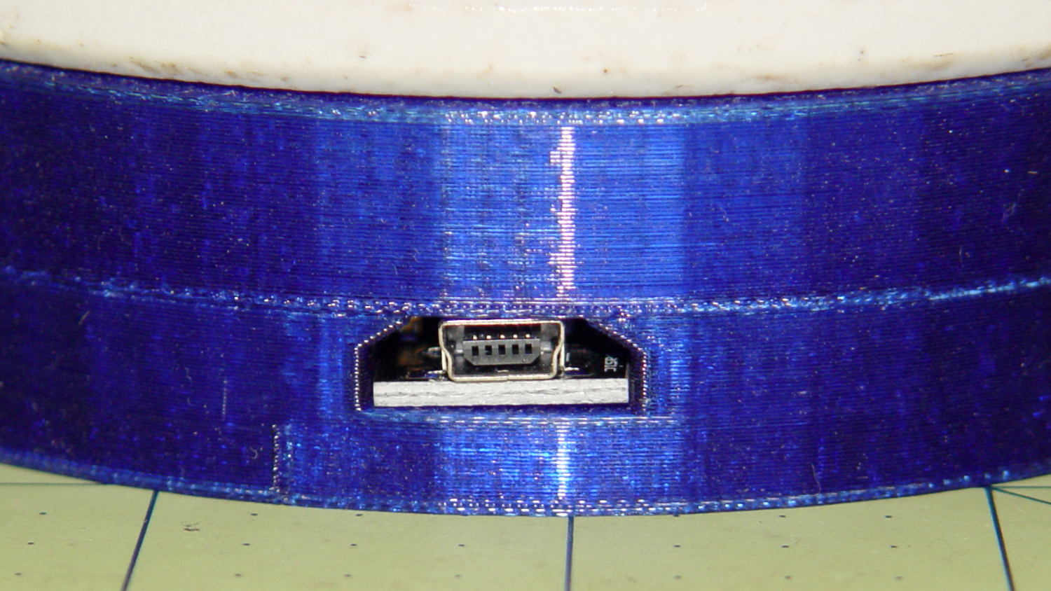
| // Aperture for USB-to-serial adapter snout | |
| // These are all magic numbers, of course | |
| module USBPort() { | |
| translate([0,28.0]) | |
| rotate([90,0,0]) | |
| linear_extrude(height=28.0) | |
| polygon(points=[ | |
| [0,0], | |
| [8.0,0], | |
| [8.0,4.0], | |
| // [4.0,4.0], | |
| [4.0,6.5], | |
| [-4.0,6.5], | |
| // [-4.0,4.0], | |
| [-8.0,4.0], | |
| [-8.0,0], | |
| ]); | |
| } | |
| //———————- | |
| // Box for Leviton ceramic lamp base | |
| module LampBase() { | |
| Bottom = 3.0; | |
| Base = [4.0*inch,4.5*inch,20.0 + Bottom]; | |
| Sides = 12*4; | |
| Retainer = [3.5,11.0,1.0]; // flat fiber washer holding lamp base screws in place | |
| StudSides = 8; | |
| StudOC = 3.5 * inch; | |
| Stud = [0.107 * inch, // 6-32 mounting screws | |
| min(15.0,1.5*(Base[ID] – StudOC)/cos(180/StudSides)), // OD = big enough to merge with walls | |
| (Base[LENGTH] – Retainer[LENGTH])]; // leave room for retainer | |
| union() { | |
| difference() { | |
| rotate(180/Sides) | |
| cylinder(d=Base[OD],h=Base[LENGTH],$fn=Sides); | |
| rotate(180/Sides) | |
| translate([0,0,Bottom]) | |
| cylinder(d=Base[ID],h=Base[LENGTH],$fn=Sides); | |
| translate([0,-Base[OD]/2,Bottom + 1.2]) // mount on double-sided foam tape | |
| rotate(0) | |
| USBPort(); | |
| } | |
| for (i = [-1,1]) | |
| translate([i*StudOC/2,0,0]) | |
| rotate(180/StudSides) | |
| difference() { | |
| # cylinder(d=Stud[OD],h=Stud[LENGTH],$fn=StudSides); | |
| translate([0,0,Bottom]) | |
| PolyCyl(Stud[ID],(Stud[LENGTH] – (Bottom – Protrusion)),6); | |
| } | |
| } | |
| } | |
| //———————- | |
| // Tube Socket | |
| module Socket(Name = "Mini7") { | |
| NumSides = 6*4; | |
| Tube = search([Name],TubeData,1,0)[0]; | |
| echo(str("Building ",TubeData[Tube][0]," socket")); | |
| echo(str(" Punch: ",TubeData[ID][T_PUNCHOD]," mm = ",TubeData[ID][T_PUNCHOD]/inch," inch")); | |
| echo(str(" Screws: ",TubeData[ID][T_SCREWOC]," mm =",TubeData[ID][T_SCREWOC]/inch," inch OC")); | |
| OAH = Pixel[LENGTH] + BaseShim + TubeData[Tube][T_PINLEN]; | |
| BaseHeight = OAH – PanelThick; | |
| difference() { | |
| union() { | |
| linear_extrude(height=BaseHeight) | |
| hull() { | |
| circle(d=(TubeData[Tube][T_PUNCHOD] + 2*SocketFlange),$fn=NumSides); | |
| for (i=[-1,1]) | |
| translate([i*TubeData[Tube][T_SCREWOC]/2,0]) | |
| circle(d=2*Nut[OD],$fn=NumSides); | |
| } | |
| cylinder(d=TubeData[Tube][T_PUNCHOD],h=OAH,$fn=NumSides); | |
| } | |
| for (i=[0:(TubeData[Tube][T_NUMPINS] – 1)]) // tube pins | |
| rotate(i*360/TubeData[Tube][T_NUMPINS]) | |
| translate([TubeData[Tube][T_PINBCD]/2,0,(OAH – TubeData[Tube][T_PINLEN])]) | |
| rotate(180/4) | |
| PolyCyl(TubeData[Tube][T_PINOD],(TubeData[Tube][T_PINLEN] + Protrusion),4); | |
| for (i=[-1,1]) // mounting screw holes & nut traps | |
| translate([i*TubeData[Tube][T_SCREWOC]/2,0,-Protrusion]) { | |
| PolyCyl(Nut[OD],(Nut[LENGTH] + Protrusion),6); | |
| PolyCyl(Nut[ID],(OAH + 2*Protrusion),6); | |
| } | |
| translate([0,0,-Protrusion]) { // LED recess | |
| PolyCyl(Pixel[OD],(Pixel[LENGTH] + Protrusion),8); | |
| } | |
| translate([0,0,(Pixel[LENGTH] – Protrusion)]) { // light pipe | |
| rotate(180/TubeData[Tube][T_NUMPINS]) | |
| PolyCyl(TubeData[Tube][T_PIPEOD],(OAH + 2*Protrusion),TubeData[Tube][T_NUMPINS]); | |
| } | |
| } | |
| // Totally ad-hoc support structures … | |
| if (Support) { | |
| color("Yellow") { | |
| for (i=[-1,1]) // nut traps | |
| translate([i*TubeData[Tube][T_SCREWOC]/2,0,(Nut[LENGTH] – ThreadThick)/2]) | |
| for (a=[0:5]) | |
| rotate(a*30 + 15) | |
| cube([2*ThreadWidth,0.9*Nut[OD],(Nut[LENGTH] – ThreadThick)],center=true); | |
| if (Pixel[OD] > TubeData[Tube][T_PIPEOD]) // support pipe only if needed | |
| translate([0,0,(Pixel[LENGTH] – ThreadThick)/2]) | |
| for (a=[0:7]) | |
| rotate(a*22.5) | |
| cube([2*ThreadWidth,0.9*Pixel[OD],(Pixel[LENGTH] – ThreadThick)],center=true); | |
| } | |
| } | |
| } | |
| //———————- | |
| // Build it | |
| if (Layout == "Cap") { | |
| if (Section) | |
| difference() { | |
| Cap(); | |
| translate([-CapSize[OD],0,CapSize[LENGTH]]) | |
| cube([2*CapSize[OD],2*CapSize[OD],3*CapSize[LENGTH]],center=true); | |
| } | |
| else | |
| Cap(); | |
| } | |
| if (Layout == "LampBase") | |
| LampBase(); | |
| if (Layout == "USBPort") | |
| USBPort(); | |
| if (Layout == "Socket") | |
| if (Section) { | |
| difference() { | |
| Socket(); | |
| translate([-100/2,0,-Protrusion]) | |
| cube([100,50,50],center=false); | |
| } | |
| } | |
| else | |
| Socket(); | |
| if (Layout == "Sockets") { | |
| translate([0,50,0]) | |
| Socket("Mini7"); | |
| translate([0,20,0]) | |
| Socket("Octal"); | |
| translate([0,-15,0]) | |
| Socket("Duodecar"); | |
| translate([0,-50,0]) | |
| Socket("Noval"); | |
| } |