The Smell of Molten Projects in the Morning

Ed Nisley's Blog: Shop notes, electronics, firmware, machinery, 3D printing, laser cuttery, and curiosities. Contents: 100% human thinking, 0% AI slop.

Tag: M2

Using and tweaking a Makergear M2 3D printer

  • MPCNC: Linear Bearing Pen Holder

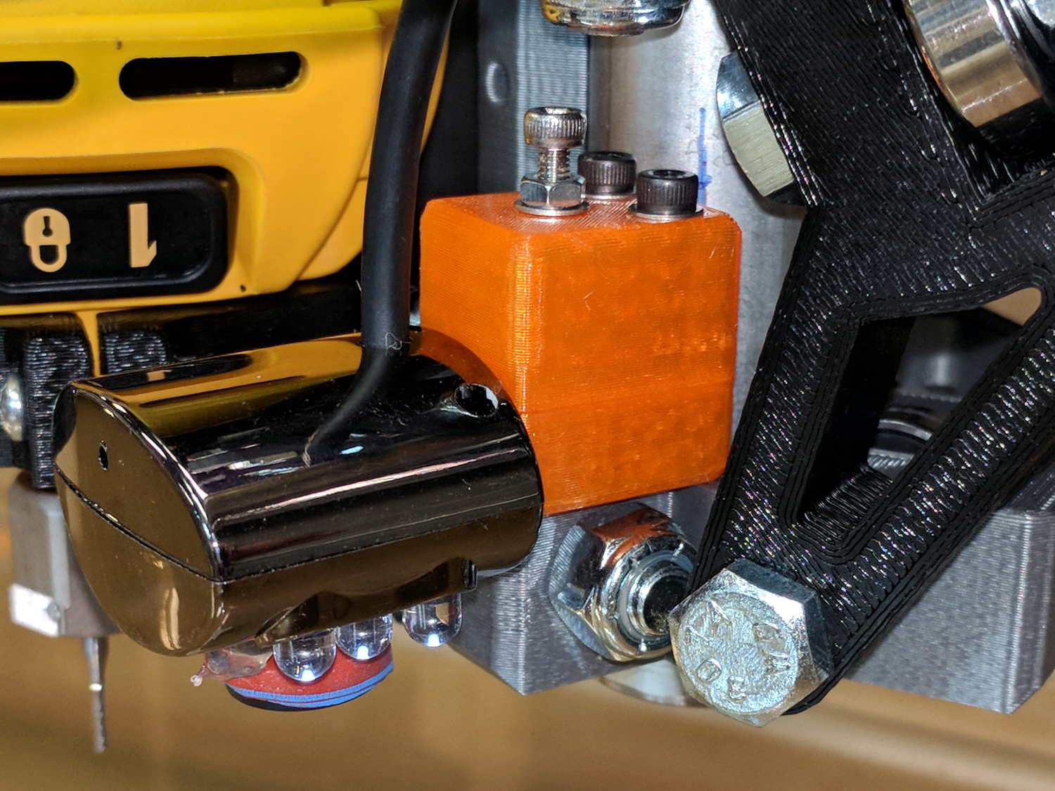
    The simplest way to push a pen (or similar thing) downward with constant force may be to hold it in a linear bearing with a weight on it, so I gimmicked up a proof-of-concept. The general idea is to mount the pen so its axis coincides with the DW660 spindle, so as to have the nib trace the same path:

    DW660 Pen Holder - unweighted
    DW660 Pen Holder – unweighted

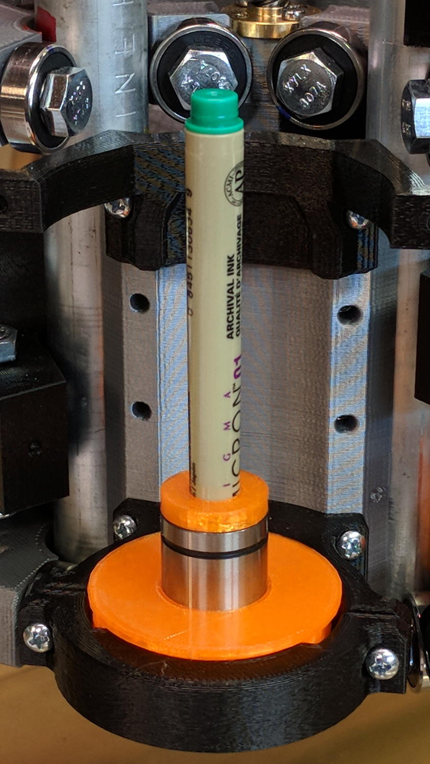
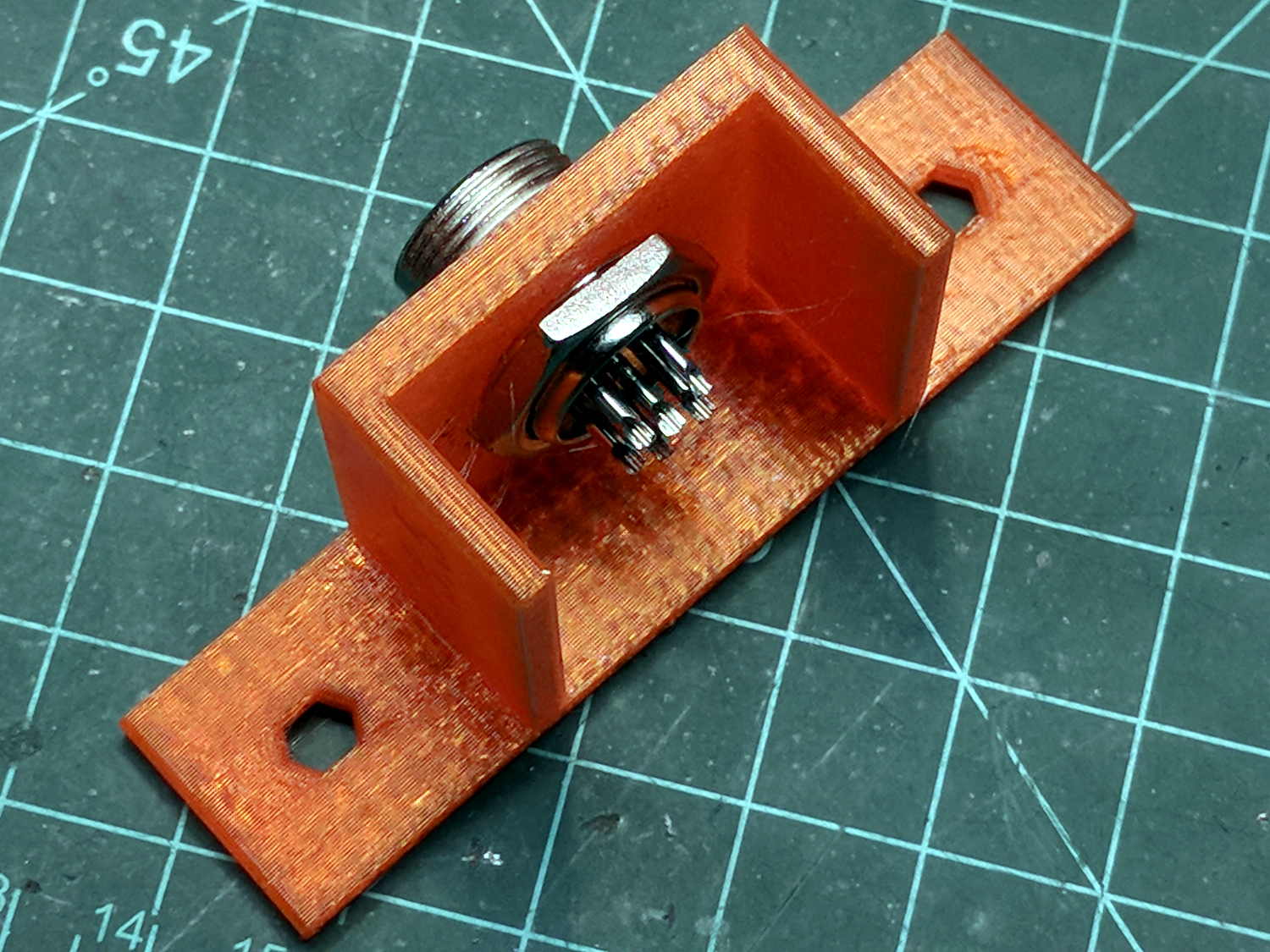
    The puck mimics the shape of the DW660 snout closely enough to satisfy the MPCNC’s tool holder:

    DW660 Pen Holder - Slic3r
    DW660 Pen Holder – Slic3r

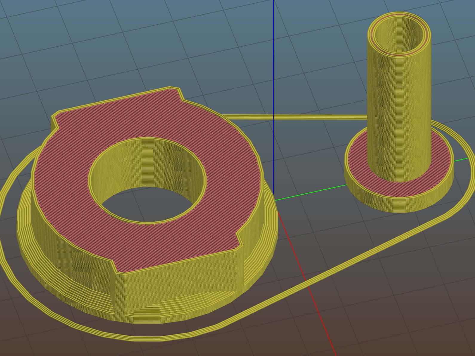
    The pen holder suffers from thin walls constrained by the 10 mm (-ish) pen OD and the 12 mm linear bearing ID, to the extent the slight infill variations produced by the tapered pen outline change the OD. A flock of 16 mm bearings, en route around the planet even as I type, should provide more meat.

    In any event, 3D printing isn’t noted for its perfect surface finish, so I applied an epoxy layer and rotated the holder as it cured:

    DW660 Pen Holder - epoxy coating
    DW660 Pen Holder – epoxy coating

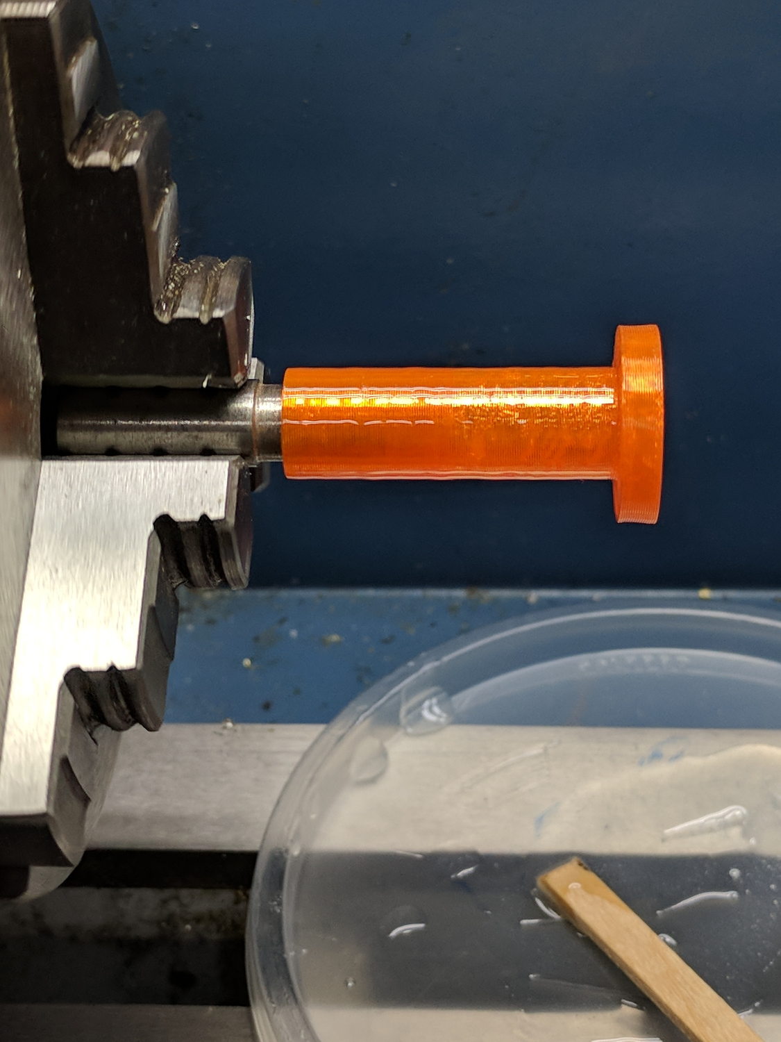
    After letting it cure overnight, I ran a lathe tool along the length to knock down the high spots and set the OD to 11.9+ mm. Although the result turns out to be a surprisingly nice fit in the bearing, there’s no way epoxy can sustain the surface load required for the usual precision steel-on-steel fit.

    A plastic pen in a plastic holder weighs 8.3 g, which isn’t quite enough to put any force on the paper. Copper weighs 9 g/cm³ = 9 mg/mm³ and 10 AWG wire is 2.54 mm OD = 5 mm², so it’s 45 mg/mm: to get 20 g, chop off 450 mm of wire.

    I chopped off a bit more than that, straightened it, annealed it, and wound it around a random contestant from the Bucket o’ Sticks with an OD just over the pen OD:

    DW660 Pen Holder - copper weight forming
    DW660 Pen Holder – copper weight forming

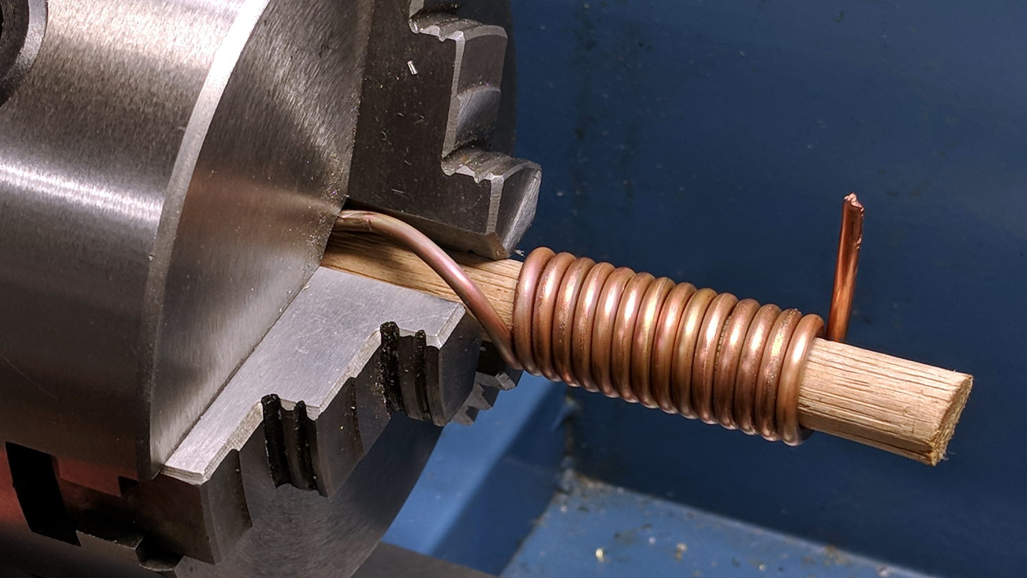
    The helix is 13.5 mm down the middle of the turns and 14 turns long (trimmed of the tail going into the chuck and fudging the tail sticking out as a partial turn), so it’s 593 mm long and should weigh 26.7 g. It actually weighs 27.6 g: close enough.

    Which is enough to overcome stiction due to the holder’s surface roughness, but the mediocre epoxy-on-balls fit allows the pen point to wander a bit too much for good results.

    The prospect of poking precise holes into 16 mm drill rod seems daunting, but, based on what I see here, it will produce much better results: rapid prototyping FTW!

    The OpenSCAD source code as a GitHub Gist:

    // MPCNC Pen Holder for DW660 Mount
    // Ed Nisley KE4ZNU – 2018-03-05
    Layout = "Build"; // Build, Show
    // Puck, MountBase, BuildBase
    // Pen, PenAdapter, BuildAdapter
    /* [Extrusion] */
    ThreadThick = 0.25; // [0.20, 0.25]
    ThreadWidth = 0.40; // [0.40]
    /* [Hidden] */
    Protrusion = 0.1; // [0.01, 0.1]
    HoleWindage = 0.2;
    inch = 25.4;
    function IntegerMultiple(Size,Unit) = Unit * ceil(Size / Unit);
    ID = 0;
    OD = 1;
    LENGTH = 2;
    //- Adjust hole diameter to make the size come out right
    module PolyCyl(Dia,Height,ForceSides=0) { // based on nophead's polyholes
    Sides = (ForceSides != 0) ? ForceSides : (ceil(Dia) + 2);
    FixDia = Dia / cos(180/Sides);
    cylinder(r=(FixDia + HoleWindage)/2,h=Height,$fn=Sides);
    }
    //- Dimensions
    WallThick = 3.0; // minimum thickness / width
    Screw = [3.0,7.0,25.0]; // holding it all together, OD = washer
    Insert = [3.0,4.4,4.5]; // brass insert
    Bearing = [12.0,21.0,30.0]; // LM12UU bearing body, ID = rod OD
    PenTravel = 5.0; // vertical pen travel allowance
    NumSides = 8*4; // cylinder facets
    //—–
    // Define shapes
    //– Sakura Micron fiber-point pen
    ExpRP = 0.30; // expand critical sections (by radius)
    //– pen locates in holder against end of outer body
    PenOutline = [
    [0,0], // 0 fiber pen tip
    [0.6/2,0.0],[0.6/2,0.9], // 1 … cylinder
    [1.5/2,0.9],[1.5/2,5.3], // 3 tip surround
    [4.7/2,5.8], // 5 chamfer
    [4.9/2,12.3], // 6 nose
    // [8.0/2,12.3],[8.0/2,13.1], // 7 latch ring
    // [8.05/2,13.1],[8.25/2,30.5], // 9 actual inner body
    [8.4/2 + ExpRP,12.3],[8.4/2 + ExpRP,30.5], // 7 inner body – clear latch ring
    [9.5/2 + ExpRP,30.9], // 9 outer body – location surface!
    [9.8/2 + ExpRP,60.0], // 10 outer body – length > Body
    [7.5/2,60.0], // 11 arbitrary length, much longer than bearing
    [7.5/2,59.0], // 12 end of reservoir
    [0,59.0] // 13 fake reservoir
    ];
    PenNose = PenOutline[6][1];
    PenLocate = PenOutline[9][1];
    // Basic shape of DW660 snout fitting into the holder
    // Lip goes upward to lock into MPCNC mount
    Snout = [44.6,50.0,9.6]; // LENGTH = ID height
    Lip = 4.0; // height of lip at end of snout
    Key = [Snout[ID],25.7,Snout[LENGTH] + Lip]; // rectangular key
    module DW660Puck() {
    cylinder(d=Snout[OD],h=Lip/2,$fn=NumSides);
    translate([0,0,Lip/2])
    cylinder(d1=Snout[OD],d2=Snout[ID],h=Lip/2,$fn=NumSides);
    cylinder(d=Snout[ID],h=Lip + Snout[LENGTH],$fn=NumSides);
    intersection() {
    translate([0,0,0*Lip + Key.z/2])
    cube(Key,center=true);
    cylinder(d=Snout[OD],h=Lip + Key.z,$fn=NumSides);
    }
    }
    module MountBase() {
    difference() {
    DW660Puck();
    translate([0,0,-Protrusion])
    PolyCyl(Bearing[OD],2*Bearing[LENGTH],NumSides);
    }
    }
    //– Sakura drawing pen body & polygon shape
    module Pen() {
    rotate_extrude($fn=NumSides)
    polygon(points=PenOutline);
    polygon(points=PenOutline);
    }
    //– Pen holder
    AdapterRing = [Bearing[ID],Bearing[OD],4.0];
    AdapterOAL = Bearing[LENGTH] + PenTravel + AdapterRing[LENGTH];
    module PenAdapter() {
    difference() {
    union() {
    PolyCyl(Bearing[ID],AdapterOAL,NumSides);
    translate([0,0,AdapterOAL – AdapterRing[LENGTH]])
    cylinder(d=AdapterRing[OD],h=AdapterRing[LENGTH],$fn=NumSides);
    }
    translate([0,0,-(PenNose + Protrusion)])
    Pen();
    }
    }
    //—–
    // Build it
    if (Layout == "Puck")
    DW660Puck();
    if (Layout == "MountBase")
    MountBase();
    if (Layout == "Pen")
    Pen();
    if (Layout == "PenAdapter")
    PenAdapter();
    if (Layout == "Show")
    MountBase();
    if (Layout == "BuildBase" || Layout == "Build")
    translate([0,-Snout[OD]/2,0])
    MountBase();
    if (Layout == "BuildAdapter" || Layout == "Build")
    translate([0,Snout[OD]/2,AdapterOAL])
    rotate([180,0,0])
    PenAdapter();
  • MPCNC: USB Camera Mount With Lock Screw

    It turned out the previous version of the USB camera mount lacked sufficient griptivity to hold the ball’s position against even moderate bumps, so the upper “half” is now tall enough to hold a lock screw directly over the ball:

    MPCNC - USB Camera mount - lock screw - Slic3r
    MPCNC – USB Camera mount – lock screw – Slic3r

    It doesn’t look much different:

    MPCNC - USB Camera Mount - lock screw
    MPCNC – USB Camera Mount – lock screw

    A view from the other side:

    USB Camera - lock screw mount
    USB Camera – lock screw mount

    The previous iterations used Genuine 3M foam tape, which seemed too flexy for comfort. This one sits on a bed of hot melt glue and is absolutely rigid. We’ll see how long it survives.

    Tightening the cap screw requires needle-nose pliers, because the whole affair has no room for a hex key.

    The OpenSCAD source code as a GitHub Gist:

    // MPCNC USB Camera Mount
    // Ed Nisley KE4ZNU – 2018-02-22
    Layout = "Build"; // Build, Show
    /* [Extrusion] */
    ThreadThick = 0.25; // [0.20, 0.25]
    ThreadWidth = 0.40; // [0.40]
    /* [Hidden] */
    Protrusion = 0.1; // [0.01, 0.1]
    HoleWindage = 0.2;
    inch = 25.4;
    function IntegerMultiple(Size,Unit) = Unit * ceil(Size / Unit);
    ID = 0;
    OD = 1;
    LENGTH = 2;
    //- Adjust hole diameter to make the size come out right
    module PolyCyl(Dia,Height,ForceSides=0) { // based on nophead's polyholes
    Sides = (ForceSides != 0) ? ForceSides : (ceil(Dia) + 2);
    FixDia = Dia / cos(180/Sides);
    cylinder(r=(FixDia + HoleWindage)/2,h=Height,$fn=Sides);
    }
    //- Dimensions
    WallThick = 3.0; // minimum thickness / width
    CameraStalk = [6.0 + 1.0,10.0 + HoleWindage,4.0]; // stalk OD, ball OD, stalk length
    CameraAngle = -5; // stalk tilt, negative = downward
    Screw = [3.0,7.0,25.0]; // holding it all together, OD = washer
    Insert = [3.0,4.4,4.5]; // brass insert
    Pusher = Insert[LENGTH] / 2; // plastic locking snippet
    UpperThick = IntegerMultiple(CameraStalk[OD]/2 + Insert[LENGTH] + Pusher + WallThick,ThreadThick);
    LowerThick = Screw[LENGTH] – UpperThick;
    MountBlock = [24.0,20.0,LowerThick + UpperThick];
    echo(str("Block: ",MountBlock));
    NumSides = 6*4;
    //—–
    // Define shapes
    // Camera mount, enlongated for E-Z differencing
    // Origin at center of ball, stalk along +X
    module Camera() {
    union() {
    sphere(d=CameraStalk[OD],$fn=NumSides);
    rotate([0,90 – CameraAngle,0])
    PolyCyl(CameraStalk[ID],3*CameraStalk[LENGTH],NumSides);
    }
    }
    // Mount block with all the cutouts
    // Ball centerline on XY plane = block split line
    module Mount(Half="All") {
    Rounding = 2.0; // corner radius
    ZShift = // block shift to remove unwanted half
    (Half == "Upper") ? -MountBlock.z/2 – 0*UpperThick :
    (Half == "Lower") ? MountBlock.z/2 + 0*LowerThick :
    2*MountBlock.z; // … want both halves, remove none
    difference() {
    hull()
    for (i=[-1,1], j=[-1,1]) {
    translate([i*(MountBlock.x/2 – Rounding),j*(MountBlock.y/2 – Rounding),(UpperThick – Rounding)])
    sphere(r=Rounding,$fn=3*4);
    translate([i*(MountBlock.x/2 – Rounding),j*(MountBlock.y/2 – Rounding),-(LowerThick – Rounding)])
    sphere(r=Rounding,$fn=3*4);
    }
    for (j=[-1,1])
    translate([-MountBlock.x/4,j*MountBlock.y/4,-(LowerThick + Protrusion)]) {
    PolyCyl(Insert[OD],Insert[LENGTH] + Protrusion,6);
    PolyCyl(Insert[ID],2*MountBlock.z,6);
    }
    translate([MountBlock.x/2 – (CameraStalk[OD]/2 + CameraStalk[LENGTH]),0,0]) {
    Camera();
    translate([0,0,UpperThick – (Insert[LENGTH] + WallThick)])
    PolyCyl(Insert[OD],Insert[LENGTH] + WallThick,6);
    PolyCyl(Insert[ID],2*UpperThick,6);
    }
    translate([0,0,ZShift])
    cube([2*MountBlock.x,2*MountBlock.y,MountBlock.z],center=true);
    }
    }
    //—–
    // Build it
    if (Layout == "Show")
    Mount("All");
    if (Layout == "Build") {
    translate([0,0.75*MountBlock.y,UpperThick])
    rotate([180,0,0])
    Mount("Upper");
    translate([0,-0.75*MountBlock.y,LowerThick])
    rotate([0,0,0])
    Mount("Lower");}
  • Baofeng BL-5 Pack Rebuild

    The 18650 cell protection PCBs with 8205 ICs arrived and seemed small enough to simply tuck into the gap between the rounded cells in the second Baofeng BL-5 pack:

    Baofeng BL-5 - new protection PCB - wiring 1
    Baofeng BL-5 – new protection PCB – wiring 1

    For whatever it might be worth, you’re looking at the only Baofeng battery pack containing an actual 10 kΩ thermistor, harvested from the benchtop Tray of Doom:

    Baofeng BL-5 pack - thermistor
    Baofeng BL-5 pack – thermistor

    Unfortunately, the components on the PCB stuck up a bit too far from the cell surface and held the lid just slightly proud of the case. Applying pressure to lithium cells being a Bad Idea, I rearranged the layout by flipping the cells over, tucking the PCB components between the cells, and connecting everything with nickel tape instead of insulated wires:

    Baofeng BL-5 - new protection PCB - wiring 2
    Baofeng BL-5 – new protection PCB – wiring 2

    The snippets of manila paper and Kapton tape hold things apart and together, as needed. Looks ugly, fits better.

    Pop it in the charger to reset the protection PCB lockout and it’s all good again.

  • Baofeng BL-5 Battery Pack Base Dimensions

    My original idea for the APRS + voice gadget was a snap-in battery pack replacement holding the circuit boards and connected to an external battery pack. A trio of dead Wouxun radios, plus the ready availability of 18650 lithium cells, suggested putting two cells in the backpack, along with the circuitry, and skipping the external pack.

    Here’s the base of a Baofeng BL-5 pack overlaid with a 1 mm grid:

    Baofeng BL-5 - Base with mm grid overlay
    Baofeng BL-5 – Base with mm grid overlay

    The grid is parallel to the case body and centered left-to-right, with a Y grid line set at the front face of the pack, where it’s also flush with the lid surface. You can read off the coordinates of all the points, feed them into your CAD model, and maybe, with a bit of care, get something 3D-print-able.

    Haven’t used it yet, but it’s bound to come in handy at some point.

  • MPCNC: Raspberry Pi Screw-down Case

    Directly from  0110-M-P’s Thingiverse thing, because a Raspberry Pi in a 75 mm VESA mount case will work for me:

    RPi in VESA case
    RPi in VESA case

    The hole fits a 25 mm fan, but the thing runs cool enough it should survive without forced air; think of it as a contingency. Mounting the case on standoffs seems like a Good Idea, however, as the bottom plate includes many vent slots for Good Circulation.

    The top plate builds upside-down, so I had Slic3r add teeny support plugs inside the recessed screw holes. I think button-head screws would fit neatly in the recesses, but we’re obviously not in this for the looks.

    The tiny white stud is a Reset switch hot-melt glued into the slot. I plan to just turn off the AC power after shutting the RPi down, so a power-on will suffice as a reset.

  • MPCNC: Power Supply Brick Mount

    A laptop-style power brick supplies 24 V for the MPCNC’s stepper motors, but I didn’t want it wandering around on the Basement Laboratory floor and getting in trouble, so a pair of brackets seemed in order:

    Power Supply Brick Mount - trial fit
    Power Supply Brick Mount – trial fit

    They build flat on their backs to avoid support material:

    Power Supply Brick Mount - Slic3r
    Power Supply Brick Mount – Slic3r

    The nicely rounded corners produce a very thin line of plastic on the first layer, so the model now has thicker base plates to improve the situation. A set of mouse ears would keep the tips pasted to the glass.

    The OpenSCAD source code as a GitHub Gist:

    // Power Supply Brick brackets
    // Ed Nisley KE4ZNU 2018-02-26
    Layout = "Show";
    //– Extrusion parameters
    ThreadThick = 0.25;
    ThreadWidth = 0.4;
    HoleWindage = 0.3; // enlarge hole dia by this amount
    function IntegerMultiple(Size,Unit) = Unit * ceil(Size / Unit);
    Protrusion = 0.1; // make holes look good and joints intersect properly
    //– Useful sizes
    inch = 25.4;
    Tap10_32 = 0.159 * inch;
    Clear10_32 = 0.190 * inch;
    Head10_32 = 0.373 * inch;
    Head10_32Thick = 0.110 * inch;
    Nut10_32Dia = 0.433 * inch;
    Nut10_32Thick = 0.130 * inch;
    ID = 0;
    OD = 1;
    LENGTH = 2;
    //– Bracket Dimensions
    Brick = [170.0,66.0,40.0]; // overall size, add details in module
    Socket = [30.0,24.0]; // IEC power socket
    Cable = [6.0,15.0]; // DC output cable ID=wire OD=strain relief
    WallThick = 3.0; // default wall thickness
    BaseThick = 4.0;
    Screw = [5.1,10.0,3.0]; // screw size, more-or-less 10-32, OD & LENGTH for head
    NumSides = 3*4;
    //———————-
    // Useful routines
    module PolyCyl(Dia,Height,ForceSides=0) { // based on nophead's polyholes
    Sides = (ForceSides != 0) ? ForceSides : (ceil(Dia) + 2);
    FixDia = Dia / cos(180/Sides);
    cylinder(r=(FixDia + HoleWindage)/2,
    h=Height,
    $fn=Sides);
    }
    //———————-
    // Models
    module BrickMount(End="Both") {
    difference() {
    union() {
    hull() // main block
    for (i=[-1,1], j=[-1,1], k=[0,1])
    translate([i*(Brick.x/2 + WallThick – WallThick),
    j*(Brick.y/2 + WallThick – WallThick),
    k*(Brick.z + WallThick – WallThick)])
    sphere(r=WallThick,$fn=NumSides);
    hull() // screw flanges
    for (i=[-1,1], j=[-1,1])
    translate([i*(Brick.x/2 + WallThick – BaseThick),
    j*(Brick.y/2 + WallThick + 2*Screw[OD] – BaseThick),
    0])
    sphere(r=BaseThick,$fn=NumSides);
    }
    for (i=[-1,1], j=[-1,1]) // remove screw holes
    translate([i*(Brick.x/2 + WallThick – Screw[OD]),
    j*(Brick.y/2 + WallThick + Screw[OD]),
    -Protrusion])
    rotate(180/6)
    PolyCyl(Screw[ID],2*WallThick,6);
    translate([0,0,Brick.z/2]) // remove center part to leave ends
    cube([(Brick.x + 2*WallThick – 4*Screw[OD]),2*Brick.y,2*Brick.z],center=true);
    if (End == "Socket")
    translate([Brick.x/2,0,Brick.z/2]) // remove cable end to leave socket
    cube([(Brick.x + 2*WallThick – 4*Screw[OD]),2*Brick.y,2*Brick.z],center=true);
    if (End == "Cable")
    translate([-Brick.x/2,0,Brick.z/2]) // remove socket end to leave cable
    cube([(Brick.x + 2*WallThick – 4*Screw[OD]),2*Brick.y,2*Brick.z],center=true);
    translate([0,0,Brick.z/2 – Protrusion/2]) // remove power supply brick from interior
    cube(Brick + [0,0,Protrusion],center=true);
    translate([0,0,-Brick.z]) // remove below XY plane
    cube(2*Brick,center=true);
    translate([0,0,Brick.z/2]) // remove AC socket
    rotate([0,-90,0])
    rotate(90)
    linear_extrude(height=Brick.x,convexity=2)
    square(Socket,center=true);
    translate([0,0,Brick.z/2]) // remove DC cable
    rotate([0,90,0])
    rotate(180/8)
    PolyCyl(Cable[OD],Brick.x,8);
    translate([Brick.x/2,0,Brick.z/4 – Protrusion/2]) // … and wire slot
    cube([Brick.x,Cable[ID],Brick.z/2 + Protrusion],center=true);
    }
    }
    //———————-
    // Build it
    if (Layout == "Show")
    BrickMount("Both");
    if (Layout == "Build") {
    translate([5,0,Brick.x/2 + WallThick])
    rotate([0,90,0])
    BrickMount("Cable");
    translate([-5,0,Brick.x/2 + WallThick])
    rotate([0,-90,0])
    BrickMount("Socket");
    }
  • MPCNC: Button Box Connector Mount

    This will eventually end up on a board supporting the GRBL controller box:

    Control Box - Connector Mount - Slic3r
    Control Box – Connector Mount – Slic3r

    It’s a direct cut-n-paste descendant of the old NEMA motor mount.

    The nut threads onto the connector behind the bulkhead, so you must either wire it in place or make very sure you can feed all the terminations through the hole:

    Connector Mount
    Connector Mount

    Given the previous hairball, I think in-situ soldering has a lot to recommend it:

    GRBL - Control button wiring
    GRBL – Control button wiring

    The OpenSCAD source code as a GitHub Gist:

    // Circular connector bracket
    // Ed Nisley KE4ZNU 2018-02-22
    //– Extrusion parameters
    ThreadThick = 0.25;
    ThreadWidth = 0.4;
    HoleWindage = 0.3; // enlarge hole dia by this amount
    function IntegerMultiple(Size,Unit) = Unit * ceil(Size / Unit);
    Protrusion = 0.1; // make holes look good and joints intersect properly
    //– Useful sizes
    inch = 25.4;
    Tap10_32 = 0.159 * inch;
    Clear10_32 = 0.190 * inch;
    Head10_32 = 0.373 * inch;
    Head10_32Thick = 0.110 * inch;
    Nut10_32Dia = 0.433 * inch;
    Nut10_32Thick = 0.130 * inch;
    ID = 0;
    OD = 1;
    LENGTH = 2;
    //– Mount Sizes
    Connector = [14.6,15.5,4.0]; // connector thread; ID = dia at flat
    Screw = [5.1,10.0,3.0]; // screw size, more-or-less 10-32, OD & LENGTH for head
    MountWidth = IntegerMultiple(2*Connector[OD],ThreadWidth); // use BCD for motor clearance
    MountThick = IntegerMultiple(Connector[LENGTH],ThreadThick); // for stiffness
    WallThick = 3.0; // default wall thickness
    StandThick = IntegerMultiple(WallThick,ThreadWidth); // baseplate
    StrutThick = IntegerMultiple(WallThick,ThreadWidth); // sides holding motor mount
    UprightLength = MountWidth + 2*StrutThick;
    StandBoltHead = IntegerMultiple(Head10_32,5); // bolt head rounded up
    StandBoltOC = IntegerMultiple(UprightLength + 2*StandBoltHead,5);
    StandLength = StandBoltOC + 2*StandBoltHead;
    StandWidth = 2*StandBoltHead;
    StandBoltClear = (StandLength – UprightLength)/2; // flat around bolt head
    Recess = StandWidth – MountThick;
    echo(str("Stand Base: ",StandLength," x ",StandWidth," x ",StandThick));
    echo(str("Stand Bolt OC: ",StandBoltOC));
    echo(str("Strut Thick: ",StrutThick));
    //———————-
    // Useful routines
    module PolyCyl(Dia,Height,ForceSides=0) { // based on nophead's polyholes
    Sides = (ForceSides != 0) ? ForceSides : (ceil(Dia) + 2);
    FixDia = Dia / cos(180/Sides);
    cylinder(r=(FixDia + HoleWindage)/2,
    h=Height,
    $fn=Sides);
    }
    //———————-
    // Model
    module MotorMount() {
    difference() {
    translate([StandThick/2,0,StandWidth/2])
    cube([(MountWidth + StandThick),StandLength,StandWidth],center=true);
    translate([-Protrusion/2,0,StandWidth – (Recess – Protrusion)/2])
    cube([(MountWidth + Protrusion),MountWidth,(Recess + Protrusion)],center=true);
    translate([0,0,-Protrusion])
    PolyCyl(Connector[OD],StandWidth,4*4);
    for (j=[-1,1]) // cutouts over bolts
    translate([-Protrusion/2,
    j*((StandLength – StandBoltClear)/2 + Protrusion/2),
    StandWidth/2])
    cube([(MountWidth + Protrusion),
    (StandBoltClear + Protrusion),
    (StandWidth + 2*Protrusion)],center=true);
    for (j=[-1,1]) // stand bolt holes
    translate([(MountWidth/2 – Protrusion),j*StandBoltOC/2,StandWidth/2])
    rotate([0,90,0])
    rotate(180/6)
    PolyCyl(Clear10_32,StandThick + 2*Protrusion,6);
    translate([0,-(UprightLength/2 – ThreadWidth/2),StandWidth/2])
    rotate([90,180,0])
    linear_extrude(ThreadWidth,convexity=10)
    text(text=str(Connector[OD]),size=6,spacing=1.20,font="Arial",halign="center",valign="center");
    }
    }
    //———————-
    // Build it
    MotorMount();