The Smell of Molten Projects in the Morning

Ed Nisley's Blog: Shop notes, electronics, firmware, machinery, 3D printing, laser cuttery, and curiosities. Contents: 100% human thinking, 0% AI slop.

Tag: M2

Using and tweaking a Makergear M2 3D printer

  • MPCNC: Drag Knife Holder

    My attempt to use a HP 7475A plotter as a vinyl cutter failed due to its 19 g pen load limit:

    HP 7475A knife stabilizer - big nut weight
    HP 7475A knife stabilizer – big nut weight

    The MPCNC, however, can apply plenty of downforce, so I tinkered up a quick-and-dirty adapter to put the drag knife “pen” body into the MPCNC’s standard DW660 router holder:

    MPCNC - DW660 adapter drag knife holder - fixed position
    MPCNC – DW660 adapter drag knife holder – fixed position

    That’s using the DW660 adapter upside-down to get the business end of the knife closer to the platform. The solid model descends from the linear-bearing Sakura pen holder by ruthless pruning.

    It didn’t work well at all, because you really need a spring for some vertical compliance and control over the downforce pressure.

    Back to the Comfy Chair:

    Drag Knife Holder - DW660 Mount - solid model
    Drag Knife Holder – DW660 Mount – solid model

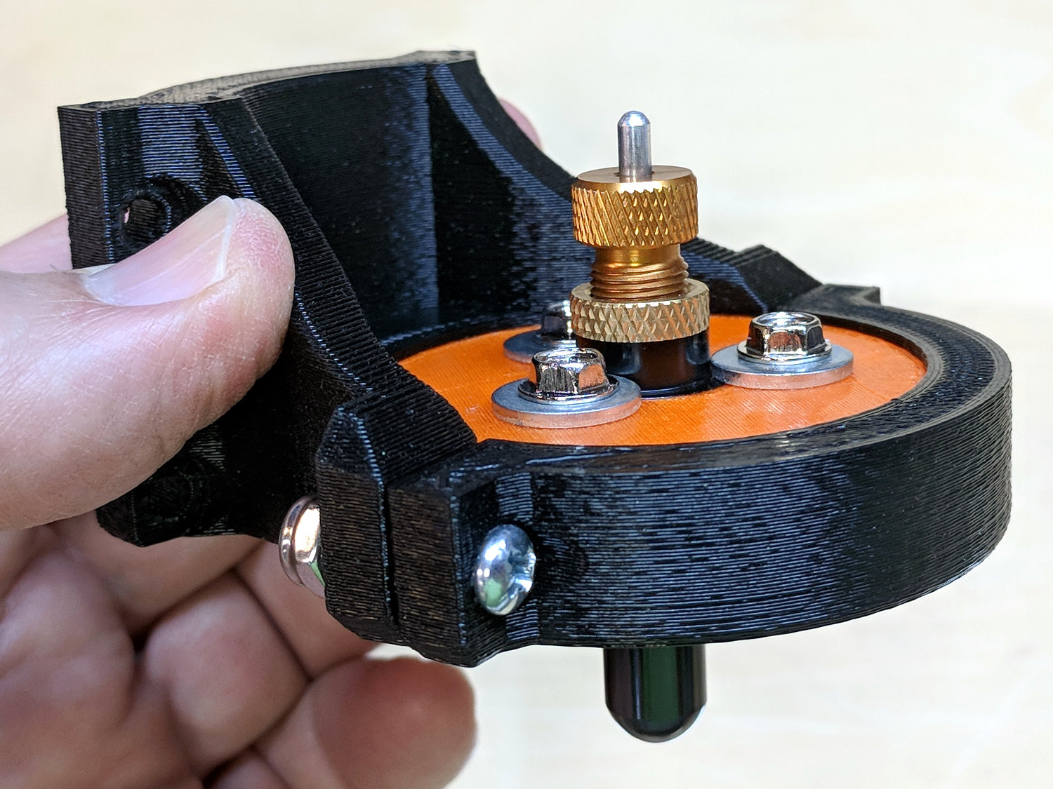
    A trio of the lightest springs from a 200 piece assortment (in the front left compartment) pushes the upper plate downward against the drag knife’s flange:

    MPCNC - DW660 adapter drag knife holder - spring loaded
    MPCNC – DW660 adapter drag knife holder – spring loaded

    There’s a bit more going on than may be obvious at first glance.

    The screws slide in brass tubing press-fit into the upper plate, because otherwise their threads hang up on the usual 3D printed layers inside the (drilled-out) holes. Smaller free-floating brass tubing snippets inside the springs keep them away from the screw threads; the gap between the top of the tubing and the screw head limits the vertical compliance to 3 mm. The screws thread into brass inserts epoxied into the bottom disk, with a dab of low-strength Loctite for stay-put adjustment.

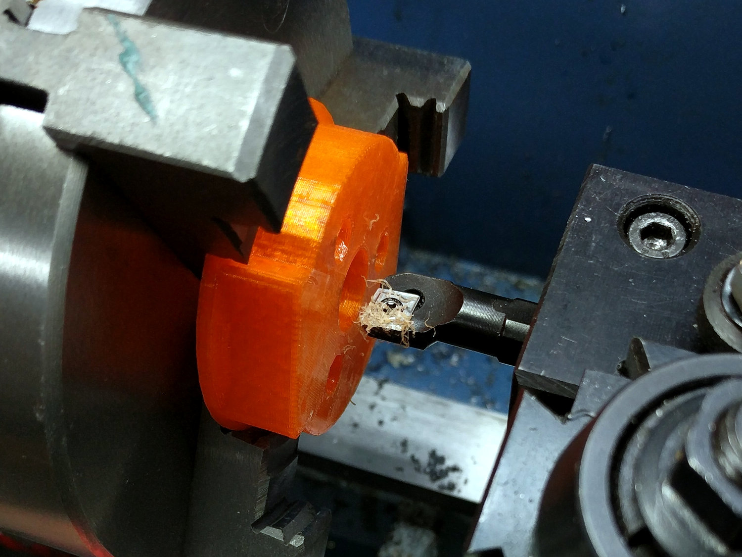
    I bored the orange PETG disk to a nice slip fit around the knife body:

    DW660 drag knife holder - boring body
    DW660 drag knife holder – boring body

    The upper plate also required fitting:

    DW660 drag knife holder - boring plate
    DW660 drag knife holder – boring plate

    A few iterations produced reasonably smooth motion over a few millimeters, but it’s definitely not a low-friction / low-stiction drag knife holder. It ought to be good for some proof-of-concept vinyl cutting, though.

    The OpenSCAD source code as a GitHub Gist:

    // Drag Knife Holder for DW660 Mount
    // Ed Nisley KE4ZNU – 2018-09-26
    Layout = "Show"; // Build, Show, Puck, Mount, Plate
    /* [Extrusion] */
    ThreadThick = 0.25; // [0.20, 0.25]
    ThreadWidth = 0.40; // [0.40]
    /* [Hidden] */
    Protrusion = 0.1; // [0.01, 0.1]
    HoleWindage = 0.2;
    inch = 25.4;
    function IntegerMultiple(Size,Unit) = Unit * ceil(Size / Unit);
    ID = 0;
    OD = 1;
    LENGTH = 2;
    //- Adjust hole diameter to make the size come out right
    module PolyCyl(Dia,Height,ForceSides=0) { // based on nophead's polyholes
    Sides = (ForceSides != 0) ? ForceSides : (ceil(Dia) + 2);
    FixDia = Dia / cos(180/Sides);
    cylinder(r=(FixDia + HoleWindage)/2,h=Height,$fn=Sides);
    }
    //- Dimensions
    KnifeBody = [12.0,16.0,2.0]; // body flange — resembles HP plotter pen
    WallThick = 3.0; // minimum thickness / width
    Screw = [4.0,8.5,8.0]; // holding it all together, OD = washer
    Insert = [4.0,6.0,10.0]; // brass insert
    Plate = [KnifeBody[ID],KnifeBody[OD] + 3*Screw[OD],4.0]; // spring reaction plate
    PlateGuide = [4.0,4.8,Plate[LENGTH]]; // … guide tubes
    NumScrews = 3;
    ScrewBCD = 2*(KnifeBody[OD]/2 + Screw[OD]/2 + 0.5);
    NumSides = 9*4; // cylinder facets (multiple of 3 for lathe trimming)
    // Basic shape of DW660 snout fitting into the holder
    // Lip goes upward to lock into MPCNC mount
    Snout = [44.6,50.0,9.6]; // LENGTH = ID height
    Lip = 4.0; // height of lip at end of snout
    PuckOAL = Snout[LENGTH] + Lip; // total height
    Key = [Snout[ID],25.7,PuckOAL]; // rectangular key
    module DW660Puck() {
    translate([0,0,PuckOAL])
    rotate([180,0,0]) {
    cylinder(d=Snout[OD],h=Lip/2,$fn=NumSides);
    translate([0,0,Lip/2])
    cylinder(d1=Snout[OD],d2=Snout[ID],h=Lip/2,$fn=NumSides);
    cylinder(d=Snout[ID],h=PuckOAL,$fn=NumSides);
    intersection() {
    translate([0,0,0*Lip + Key.z/2])
    cube(Key,center=true);
    cylinder(d=Snout[OD],h=Lip + Key.z,$fn=NumSides);
    }
    }
    }
    module MountBase() {
    difference() {
    DW660Puck();
    translate([0,0,-Protrusion]) // knife holder body
    PolyCyl(KnifeBody[ID],2*PuckOAL,NumSides);
    translate([0,0,PuckOAL – KnifeBody[LENGTH]/2]) // … half of flange, loose fit
    PolyCyl(KnifeBody[OD] + 2*HoleWindage,KnifeBody[LENGTH],NumSides);
    for (i=[0:NumScrews – 1]) // clamp screws
    rotate(i*360/NumScrews)
    translate([ScrewBCD/2,0,-Protrusion])
    rotate(180/8)
    PolyCyl(Insert[OD],2*PuckOAL,8);
    }
    }
    module SpringPlate() {
    difference() {
    cylinder(d=Plate[OD],h=Plate[LENGTH],$fn=NumSides);
    translate([0,0,-Protrusion]) // knife holder body
    PolyCyl(KnifeBody[ID],2*PuckOAL,NumSides);
    translate([0,0,Plate[LENGTH] – KnifeBody[LENGTH]/2]) // … half of flange, snug fit
    PolyCyl(KnifeBody[OD],KnifeBody[LENGTH],NumSides);
    for (i=[0:NumScrews – 1]) // clamp screws
    rotate(i*360/NumScrews)
    translate([ScrewBCD/2,0,-Protrusion])
    rotate(180/8)
    PolyCyl(PlateGuide[OD],2*PuckOAL,8);
    }
    }
    //—–
    // Build it
    if (Layout == "Puck")
    DW660Puck();
    if (Layout == "Plate")
    SpringPlate();
    if (Layout == "Mount")
    MountBase();
    if (Layout == "Show") {
    MountBase();
    translate([0,0,2*PuckOAL])
    rotate([180,0,0])
    SpringPlate();
    }
    if (Layout == "Build") {
    translate([0,Snout[OD]/2,0])
    MountBase();
    translate([0,-Snout[OD]/2,0])
    SpringPlate();
    }


  • Fireball Island Figures

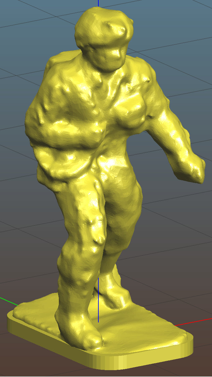
    A cousin asked if my 3D printer could replace some figures gone missing from their old Fireball Island game board, a classic apparently coming out in a new & improved version.

    Fortunately, solid models exist on Thingiverse:

    Fireball Island figure - Thingiverse 536867
    Fireball Island figure – Thingiverse 536867

    Unfortunately, the left arm requires support, which Slic3r supplies with great exuberance:

    Fireball Island figure - Slic3r support
    Fireball Island figure – Slic3r support

    The vast tower on the figure’s right side (our left) seemed completely unnecessary, not to mention I have no enthusiasm for the peril inherent in chopping away so much plastic, so I replaced it with a simple in-model pillar:

    Figure Support Mods
    Figure Support Mods

    The pillar leans from an adhesion-enhancing lily pad and ends one layer below the left hand, with all dimensions and angles chosen on the fly to make the answer come out right.

    Works like a champ:

    Fireball Island Figures - orange - on platform
    Fireball Island Figures – orange – on platform

    The dark band down the middle comes from the Pixel’s shutter.

    They emerged with some PETG hair, the removal of which I left as an end-user experience.

    I mailed a small box containing figures printed in my (limited!) palette of four colors, some spares Just In Case™, and a few QC rejects showing the necessity of lily pads.

    Game on!

    The OpenSCAD source code as a GitHub Gist:

    // Adding support under Fireball Island figure arm
    import("/mnt/bulkdata/Project Files/Thing-O-Matic/Fireball Island/Fireball Island figure – 100k.stl", convexity=5);
    translate([6.5,-4.0,0]) {
    intersection(){
    translate([-10/2,-10/2,0])
    cube([10,10,11.6],center=false);
    rotate([0,-5.0,0])
    rotate(180/6)
    cylinder(d=4.0,h=30,$fn=6,center=true);
    }
    translate([8/4,0,0])
    rotate(180/6)
    cylinder(d=8,h=0.2,$fn=6);
    }
  • Tour Easy Daytime Running Light: First Fracture

    A wind gust pushed Mary’s bike over with the daytime running light on the downward side:

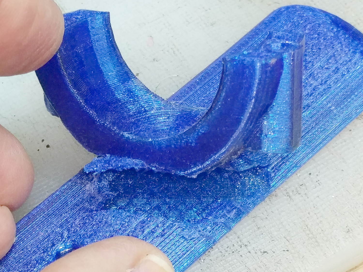
    Fairing Flashlight Mount - Fracture
    Fairing Flashlight Mount – Fracture

    Frankly, it’s better to have a cheap and easily replaceable plastic widget break, instead of something expensive and hard to find.

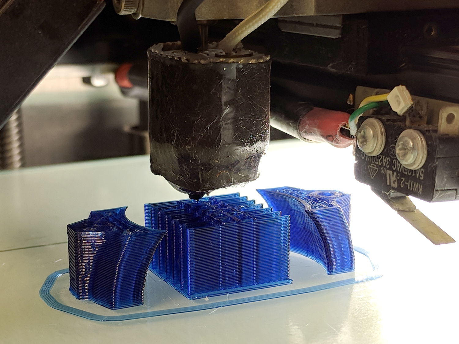
    Because we live in the future, a replacement part was just a few hours away:

    M2 - Nozzle Z Offset Recal - DRL Clamp
    M2 – Nozzle Z Offset Recal – DRL Clamp

    Well, a few hours after installing a replacement thermistor and recalibrating the M2, but nested repairs happen every now and again.

    To the road!

  • Makergear M2: Nozzle Z Offset Recalibration

    After a few days of downtime, an Official Makergear Thermistor arrived and is now installed amid a dab of heatsink compound:

    M2 - Thermistor with heatsink compound
    M2 – Thermistor with heatsink compound

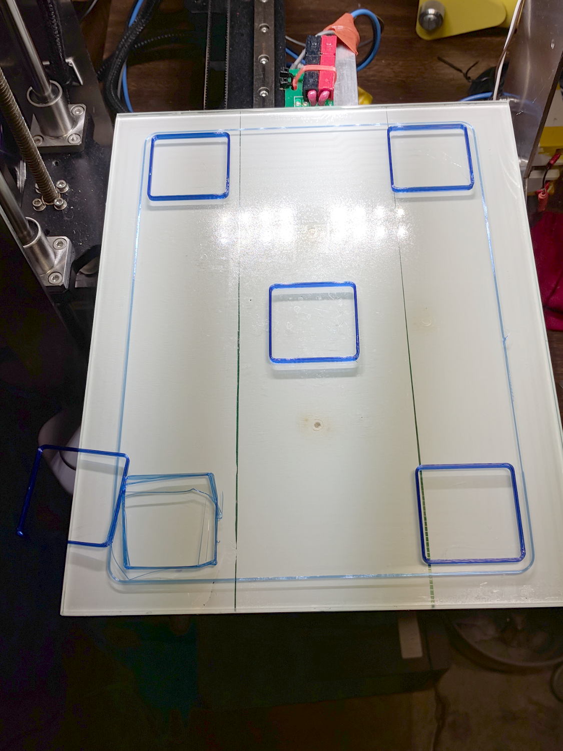
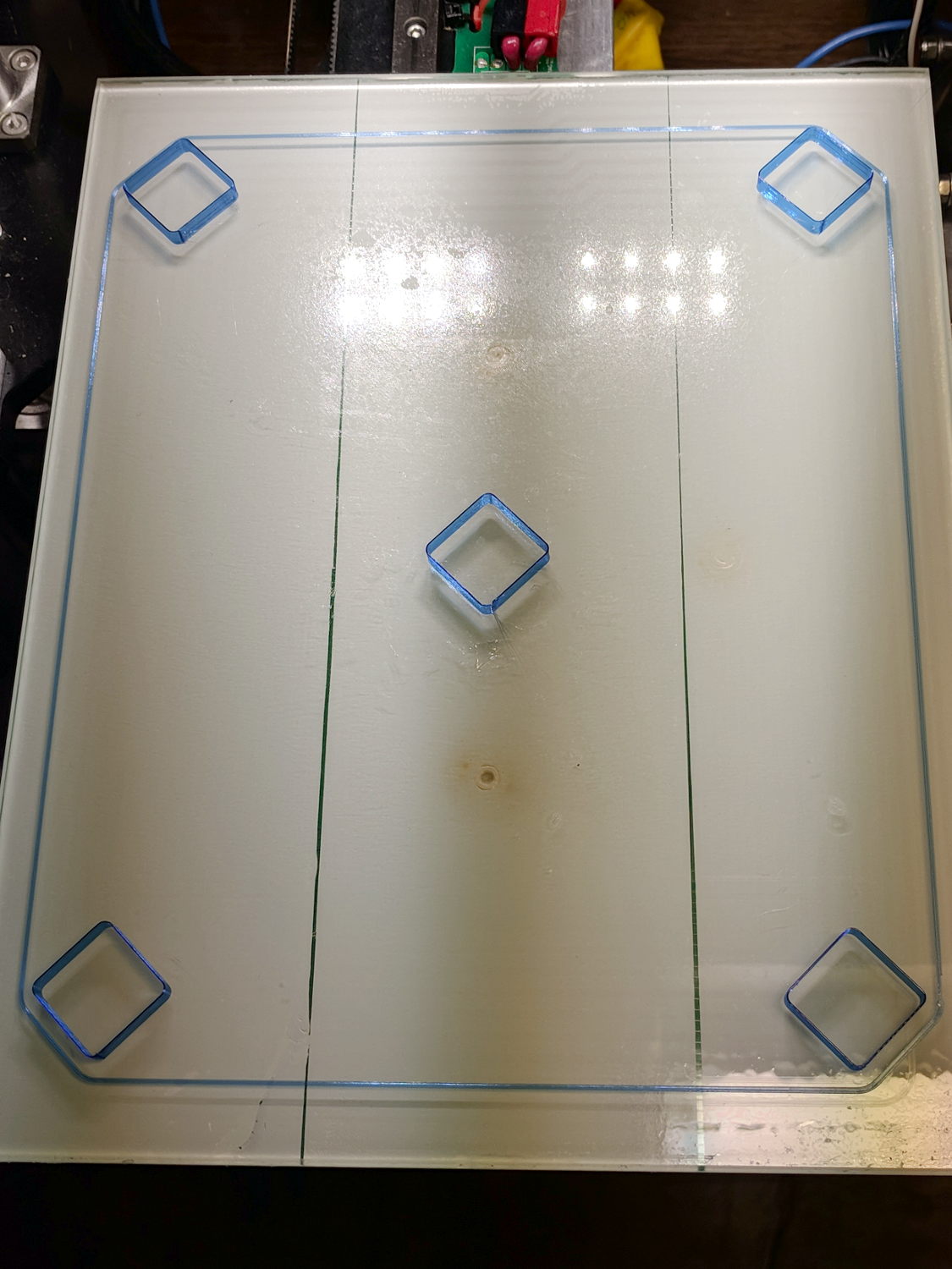
    With the hot end set a bit higher than usual, position the platform at Z=0, lower the nozzle to be flat on the platform, tighten the lock screw, then run off a set of large calibration squares:

    M2 - Nozzle Z Offset Recal - first test
    M2 – Nozzle Z Offset Recal – first test

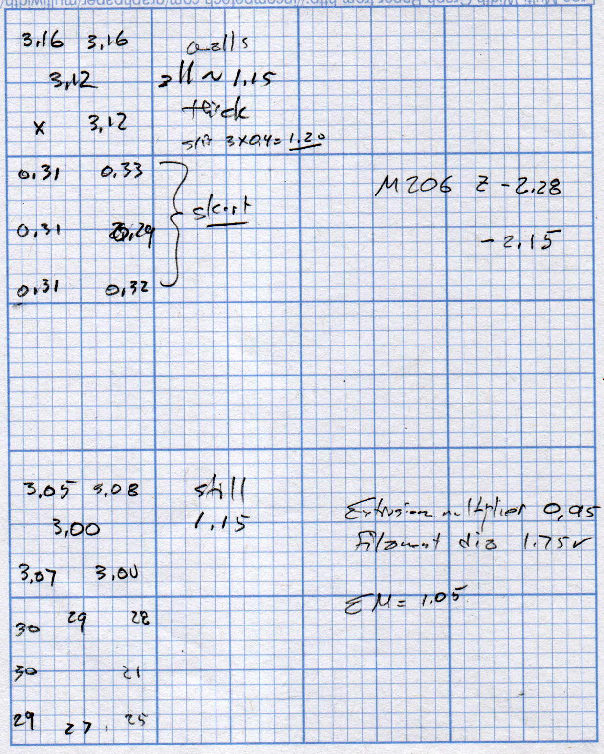
    The scrambled square in the front left says the Z=0 nozzle position came out just a bit too far above the platform and, indeed, the measurements (upper left numbers) say it’s off by 0.15-ish mm:

    M2 Nozzle and Platform Re-Cal Measurements
    M2 Nozzle and Platform Re-Cal Measurements

    Probably a little PETG stuck to the nozzle; I hate adjusting things when they’re burning hot.

    The walls are also thin by a smidge, but the first order of business is to reset the Z offset with M206 Z=-2.15. With that in hand, the second set of squares came out at 3.00 to 3.08 mm (lower left numbers), which I defined to be Close Enough.

    The 0.08 mm variation across the platform isn’t enough to worry about.

    The first skirt threads were too thick and not solidly bonded together, but the second skirt came out normally, with a thickness from 0.21 through 0.30, which is also Good Enough.

    The three-thread walls were still 1.15 mm, rather than 1.20 mm, so the EM should go from 0.95 to 0.95*1.20/1.15 = 1.05.

    Next, a set of single-thread thinwall boxes to verify the Z offset and recheck the Extrusion Multiplier:

    M2 - Nozzle Z Offset Recal - thinwall test
    M2 – Nozzle Z Offset Recal – thinwall test

    They’re dead on 3.00 mm tall, varying by not enough to worry about.

    Their single-thread walls are 0.38 mm, not the intended 0.40, which suggests the EM should become 0.95*0.40/0.35 = 1.00.

    It turns out the filament diameter at this part of the roll is scant of 1.75 mm, maybe 1.73 mm, so I decided to not fiddle with the EM.

    The first production part came out fine:

    M2 - Nozzle Z Offset Recal - DRL Clamp
    M2 – Nozzle Z Offset Recal – DRL Clamp

    The flange around the bottom of the arch support grid (in the middle) is intentional; it’s not an overstuffed first layer. The clamp sections rise from the platform just like they grew there.

    So the M2 is back in operation and I have a spare thermistor on the shelf!

  • M2 DIY Thermistor Rebuild: Autopsy

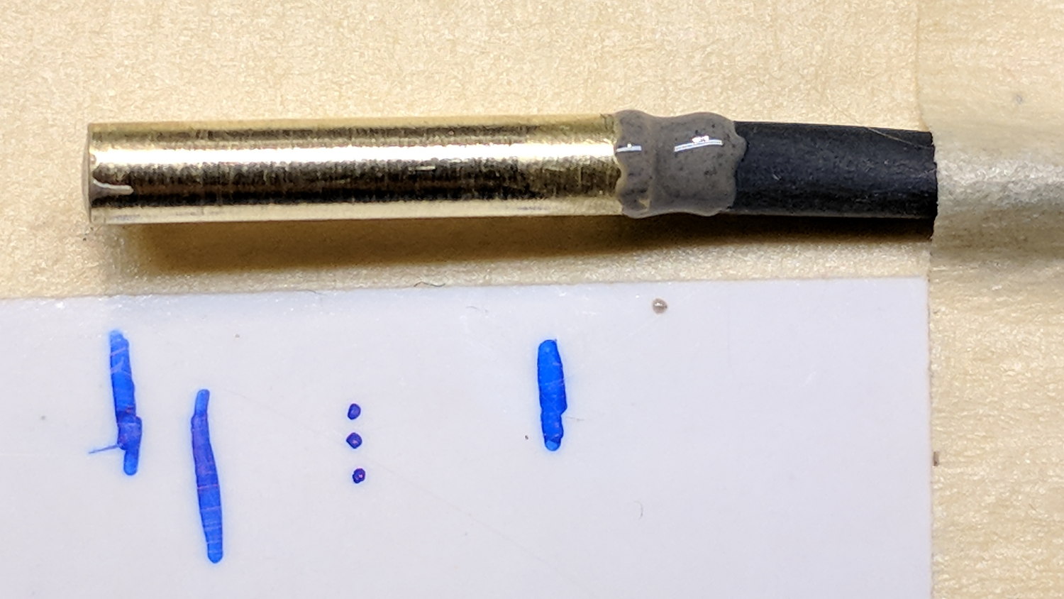
    Not much to my surprise, my hack-job thermistor rebuild went bad:

    M2 - thermistor - assembly 2
    M2 – thermistor – assembly 2

    Having nothing to lose, I heated the brass tube over a butane flame to wreck the epoxy, which blew out with a satisfactory bang and filled the Basement Laboratory with The Big Stink.

    Much to my surprise, the active ingredient still worked:

    M2 DIY thermistor corpse
    M2 DIY thermistor corpse

    The multimeter reported absolutely no intermittent dropouts for as long as I was willing to watch the trace while doing other things:

    DIY Thermistor Autopsy - Resistance Trend
    DIY Thermistor Autopsy – Resistance Trend

    So it must be my crappy soldering technique.

    A brace of real M2 thermistors will arrive shortly …

  • Rubber Soaker Hose Repair

    A soaker hose leaped under a descending garden fork and accumulated a nasty gash:

    Soaker Hose Splice - gashed
    Soaker Hose Splice – gashed

    Mary deployed a spare and continued the mission, while I pondered how to fix such an odd shape.

    For lack of anything smarter, I decided to put a form-fitting clamp around the hose, with silicone caulk buttered around the gash to (ideally) slow down any leakage:

    Soaker Hose Splice - Solid Model - Assembled
    Soaker Hose Splice – Solid Model – Assembled

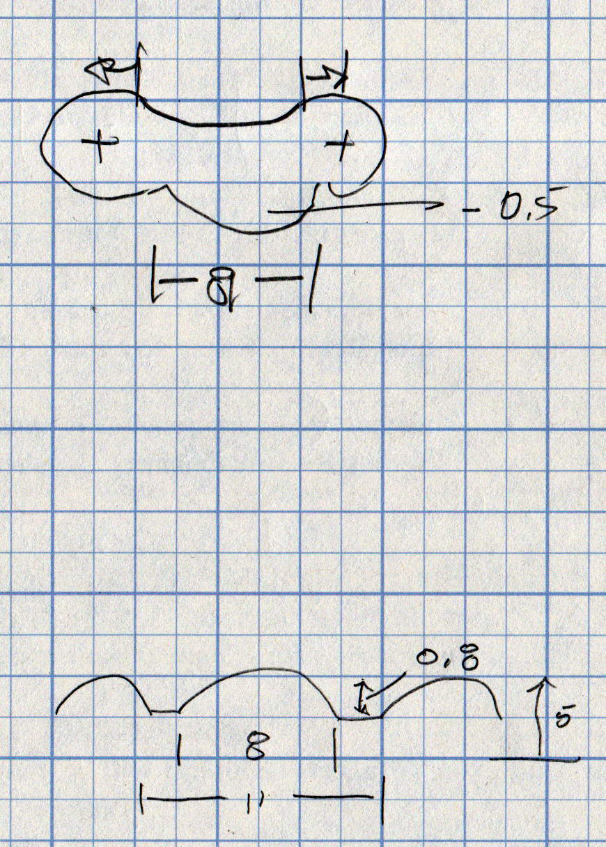
    As usual, some doodling got the solid model started:

    Soaker Hose Splice - Dimension doodle 1
    Soaker Hose Splice – Dimension doodle 1

    A hose formed from chopped rubber doesn’t really have consistent dimensions, so I set up the model to spit out small test pieces:

    Soaker Hose Splice - Test Fit - Slic3r
    Soaker Hose Splice – Test Fit – Slic3r

    Lots and lots of test pieces:

    Soaker Hose Splice - test pieces
    Soaker Hose Splice – test pieces

    Each iteration produced a better fit, although the dimensions never really converged:

    Soaker Hose Splice - Dimension doodle 2
    Soaker Hose Splice – Dimension doodle 2

    The overall model looks about like you’d expect:

    Soaker Hose Splice - Complete - Slic3r
    Soaker Hose Splice – Complete – Slic3r

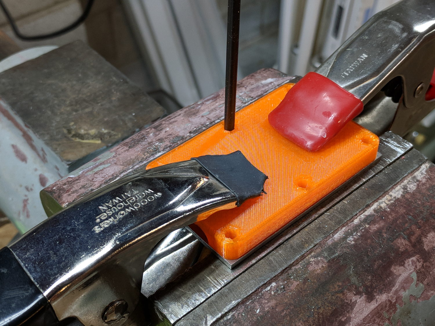
    The clamp must hold its shape around a hose carrying 100 psi (for real!) water, so I put 100 mil aluminum backing plates on either side. Were you doing this for real, you’d shape the plates with a CNC mill, but I just bandsawed them to about the right size and transfer-punched the hole positions:

    Soaker Hose Splice - plate transfer punch
    Soaker Hose Splice – plate transfer punch

    Some drill press action with a slightly oversize drill compensated for any misalignment and Mr Disk Sander rounded the corners to match the plastic block:

    Soaker Hose Splice - plate corner rounding
    Soaker Hose Splice – plate corner rounding

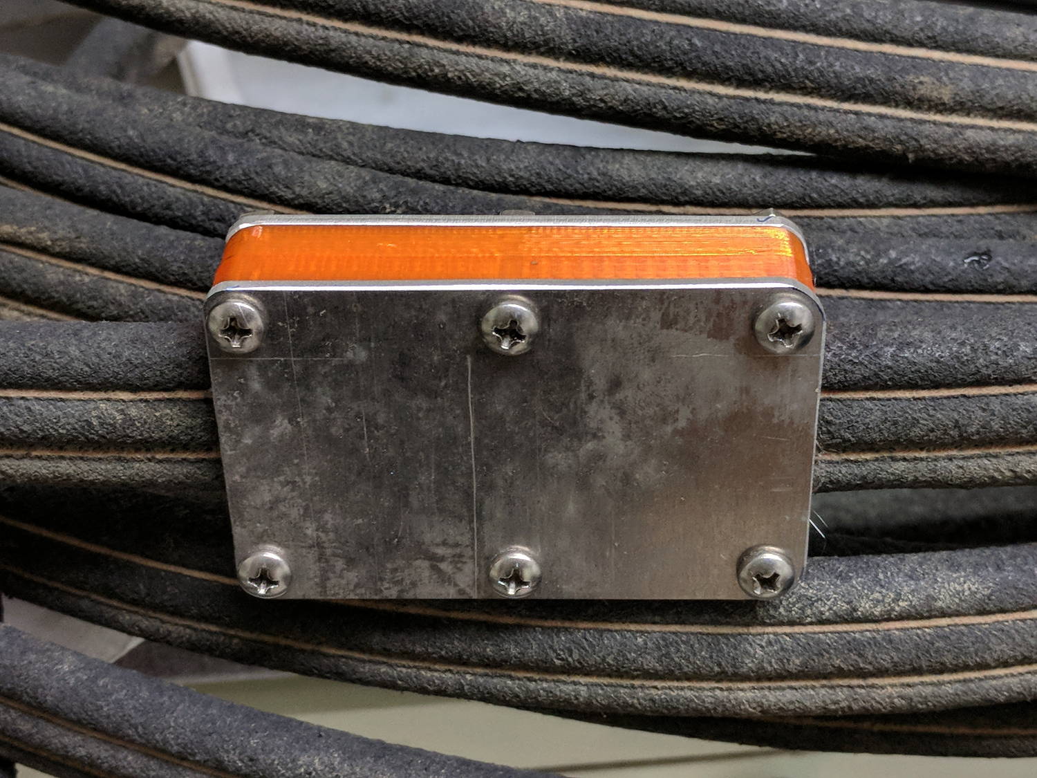
    A handful of stainless steel 8-32 screws holds the whole mess together:

    Soaker Hose Splice - installed
    Soaker Hose Splice – installed

    These hoses spend their lives at rest under a layer of mulch, so I’m ignoring the entire problem of stress relief at those sharp block edges. We’ll see how this plays out in real life, probably next year.

    I haven’t tested it under pressure, but it sure looks capable!

    The OpenSCAD source code as a GitHub Gist:

    // Rubber Soaker Hose Splice
    // Ed Nisley KE4ZNU July 2018
    Layout = "Build"; // Hose Block Show Build
    TestFit = false; // true to build test fit slice from center
    //- Extrusion parameters must match reality!
    ThreadThick = 0.25;
    ThreadWidth = 0.40;
    HoleWindage = 0.2;
    Protrusion = 0.1; // make holes end cleanly
    inch = 25.4;
    function IntegerMultiple(Size,Unit) = Unit * ceil(Size / Unit);
    //———-
    // Dimensions
    // Hose lies along X axis
    Hose = [200,27.0,12.0]; // X = longer than anything else
    Block = [80.0,50.0,4.0 + Hose.z]; // overall splice block size
    echo(str("Block: ",Block));
    Kerf = 0.1; // cut through middle to apply compression
    ID = 0;
    OD = 1;
    LENGTH = 2;
    // 8-32 stainless screws
    Screw = [4.1,8.0,3.0]; // OD = head LENGTH = head thickness
    Washer = [4.4,9.5,1.0];
    Nut = [4.1,9.7,6.0];
    CornerRadius = Washer[OD]/2;
    NumScrews = 3; // screws along each side of cable
    ScrewOC = [(Block.x – 2*CornerRadius) / (NumScrews – 1),
    Block.y – 2*CornerRadius,
    2*Block.z // ensure complete holes
    ];
    echo(str("Screw OC: x=",ScrewOC.x," y=",ScrewOC.y));
    //———————-
    // Useful routines
    module PolyCyl(Dia,Height,ForceSides=0) { // based on nophead's polyholes
    Sides = (ForceSides != 0) ? ForceSides : (ceil(Dia) + 2);
    FixDia = Dia / cos(180/Sides);
    cylinder(d=(FixDia + HoleWindage),h=Height,$fn=Sides);
    }
    // Hose shape
    // This includes magic numbers measured from reality
    module HoseProfile() {
    RimThick = 10.0; // outer sections
    RimOD = RimThick;
    RimFlatRecess = -0.7; // recess to front flat surface
    OuterOC = Hose.y – RimOD; // outer tube centers
    RecessM = 1.5; // back recess chord
    RecessC = OuterOC;
    RecessR = (pow(RecessM,2) + pow(RecessC,2)/4) / (2*RecessM);
    RidgeM = 1.0; // front ridge chord
    RidgeC = 8.0;
    RidgeR = (pow(RidgeM,2) + pow(RidgeC,2)/4) / (2*RidgeM);
    NumSides = 12*4;
    rotate([0,-90,0])
    translate([0,0,-Hose.x/2])
    linear_extrude(height=Hose.x,convexity=4)
    difference() {
    union() {
    for (j=[-1,1]) // outer channels
    translate([0,j*OuterOC/2])
    circle(d=RimOD,$fn=NumSides);
    translate([-RimOD/4,0]) // rear flat fill
    square([RimOD/2,OuterOC],center=true);
    translate([(RimOD/4 + RimFlatRecess),0]) // front flat fill
    square([RimOD/2,OuterOC],center=true);
    intersection() {
    translate([Hose.z/2,0])
    square([Hose.z,OuterOC],center=true);
    translate([-RidgeR + RimOD/2 + RimFlatRecess + RidgeM,0])
    circle(r=RidgeR,$fn=NumSides);
    }
    }
    translate([-(RecessR + RimOD/2 – RecessM),0])
    circle(r=RecessR,$fn=2*NumSides);
    }
    }
    // Outside shape of splice Block
    // Z centered on hose rim circles, not overall thickness through center ridge
    module SpliceBlock() {
    difference() {
    hull()
    for (i=[-1,1], j=[-1,1]) // rounded block
    translate([i*(Block.x/2 – CornerRadius),j*(Block.y/2 – CornerRadius),-Block.z/2])
    cylinder(r=CornerRadius,h=Block.z,$fn=4*8);
    for (i = [0:NumScrews – 1], j=[-1,1]) // screw holes
    translate([-(Block.x/2 – CornerRadius) + i*ScrewOC.x,
    j*ScrewOC.y/2,
    -(Block.z/2 + Protrusion)])
    PolyCyl(Screw[ID],Block.z + 2*Protrusion,6);
    cube([2*Block.x,2*Block.y,Kerf],center=true); // slice through center
    }
    }
    // Splice block less hose
    module ShapedBlock() {
    difference() {
    SpliceBlock();
    HoseProfile();
    }
    }
    //———-
    // Build them
    if (Layout == "Hose")
    HoseProfile();
    if (Layout == "Block")
    SpliceBlock();
    if (Layout == "Bottom")
    BottomPlate();
    if (Layout == "Top")
    TopPlate();
    if (Layout == "Show") {
    difference() {
    SpliceBlock();
    HoseProfile();
    }
    color("Green",0.25)
    HoseProfile();
    }
    if (Layout == "Build") {
    SliceOffset = TestFit && !NumScrews%2 ? ScrewOC.x/2 : 0;
    intersection() {
    translate([SliceOffset,0,Block.z/4])
    if (TestFit)
    cube([ScrewOC.x/2,4*Block.y,Block.z/2],center=true);
    else
    cube([4*Block.x,4*Block.y,Block.z/2],center=true);
    union() {
    translate([0,0.6*Block.y,Block.z/2])
    ShapedBlock();
    translate([0,-0.6*Block.y,Block.z/2])
    rotate([0,180,0])
    ShapedBlock();
    }
    }
    }
  • Tour Easy Front Fender Clip: Longer and Stronger

    We negotiated the Belmar Bridge connection stairway from the Allegheny River Trail to the Sandy Creek trail:

    Belmar Bridge Stairs - Overview
    Belmar Bridge Stairs – Overview

    We’re maneuvering Mary’s bike, but you get the general idea. Our bikes aren’t built for stairways, particularly ones with low overheads:

    Belmar Bridge Stairs - Low Overhead
    Belmar Bridge Stairs – Low Overhead

    The front fender clip on my Tour Easy snapped (at the expected spots) when the mudflap snagged on one of the angles:

    Belmar Bridge Stairs - First Turn
    Belmar Bridge Stairs – First Turn

    For some inexplicable reason, I didn’t have a roll of duct tape in my packs, so the temporary repair required a strip of tape from a battery pack, two snippets of hook-and-loop tape, and considerable muttering:

    Tour Easy front fender clip - expedient repair
    Tour Easy front fender clip – expedient repair

    It was good for two dozen more miles to the end of our vacation, so I’d say that was Good Enough.

    The new version has holes in the ferrules ten stay diameters deep, instead of six, which might eliminate the need for heatstink tubing. I added a small hole at the joint between the curved hooks and the ferrules to force more plastic into those spots:

    Front Fender Clip - Slic3r
    Front Fender Clip – Slic3r

    I also bent the hanger extension to put the fender’s neutral position closer to the wheel.

    We’ll see how long this one lasts. By now, I now have black double-sticky foam tape!

    The OpenSCAD source code as a GitHub Gist:

    // Tour Easy front fender clip
    // Ed Nisley KE4ZNU July 2017
    Layout = "Build"; // Build Profile Ferrule Clip
    //- Extrusion parameters must match reality!
    ThreadThick = 0.25;
    ThreadWidth = 0.40;
    HoleWindage = 0.2;
    Protrusion = 0.1; // make holes end cleanly
    inch = 25.4;
    function IntegerMultiple(Size,Unit) = Unit * ceil(Size / Unit);
    //———————-
    // Dimensions
    // special case: fender is exactly half a circle!
    FenderC = 51.0; // fender outside width = chord
    FenderM = 21.0; // height of chord
    FenderR = (pow(FenderM,2) + pow(FenderC,2)/4) / (2 * FenderM); // radius
    echo(str("Fender radius: ", FenderR));
    FenderD = 2*FenderR;
    FenderA = 2 * asin(FenderC / (2*FenderR));
    echo(str(" … Arc: ",FenderA," deg"));
    FenderThick = 2.5; // fender thickness, assume dia of edge
    ClipHeight = 15.0; // top to bottom, ignoring rakish tilt
    ClipThick = IntegerMultiple(2.5,ThreadWidth); // thickness of clip around fender
    ClipD = FenderD; // ID of clip against fender
    ClipSides = 4 * 8; // polygon sides around clip circle
    BendReliefD = 2.5; // bend arch diameter
    BendReliefA = 2/3 * FenderA/2; // … angle from dead ahead
    BendReliefCut = 1.5; // factor to thin outside of bend
    ID = 0;
    OD = 1;
    LENGTH = 2;
    StayDia = 3.3; // fender stay rod diameter
    StayOffset = 15.0; // stay-to-fender distance
    StayPitch = -5; // angle from stay to fender arch
    DropoutSpace = 120; // stay spacing at wheel hub
    StayLength = 235; // stay length: hub to fender
    StaySplay = asin((DropoutSpace – FenderC)/(2*StayLength)); // outward angle to hub
    echo(str(" … Pitch: ",StayPitch," deg"));
    echo(str(" … Splay: ",StaySplay," deg"));
    FerruleSides = 2*4;
    Ferrule = [StayDia,3*FenderThick/cos(180/FerruleSides),10*StayDia + StayOffset]; // ID = stay rod OD
    FerruleHoleD = 0.1; // small hole to create solid plastic at ferrule joint
    //———————-
    // Useful routines
    module PolyCyl(Dia,Height,ForceSides=0) { // based on nophead's polyholes
    Sides = (ForceSides != 0) ? ForceSides : (ceil(Dia) + 2);
    FixDia = Dia / cos(180/Sides);
    cylinder(r=(FixDia + HoleWindage)/2,
    h=Height,
    $fn=Sides);
    }
    //———————-
    // Clip profile around fender
    // Centered on fender arc
    module Profile(HeightScale = 1) {
    linear_extrude(height=HeightScale*ClipHeight,convexity=5) {
    difference() {
    offset(r=ClipThick) // outside of clip
    union() {
    circle(d=ClipD,$fn=ClipSides);
    for (i=[-1,1])
    rotate(i*BendReliefA) {
    translate([ClipD/2 + BendReliefD/2,0,0])
    circle(d=BendReliefD,$fn=6);
    }
    }
    union() { // inside of clip
    circle(d=ClipD,$fn=ClipSides);
    for (i=[-1,1])
    rotate(i*BendReliefA) {
    translate([ClipD/2 + BendReliefCut*BendReliefD/2,0,0])
    circle(d=BendReliefD/cos(180/6),$fn=6);
    translate([ClipD/2,0,0])
    square([BendReliefCut*BendReliefD,BendReliefD],center=true);
    }
    }
    translate([(FenderR – FenderM – FenderD/2),0]) // trim ends
    square([FenderD,2*FenderD],center=true);
    }
    for (a=[-1,1]) // hooks around fender
    rotate(a*(FenderA/2))
    translate([FenderR – FenderThick/2,0]) {
    difference() {
    rotate(1*180/12)
    circle(d=FenderThick + 2*ClipThick,$fn=12);
    rotate(1*180/8)
    circle(d=FenderThick,$fn=8);
    rotate(a * -90)
    translate([0,-2*FenderThick,0])
    square(4*FenderThick,center=false);
    }
    }
    }
    }
    //———————-
    // Ferrule body
    module FerruleBody() {
    translate([0,0,Ferrule[OD]/2 * cos(180/FerruleSides)])
    rotate([0,-90,0]) rotate(180/FerruleSides)
    difference() {
    cylinder(d=Ferrule[OD],h=Ferrule[LENGTH],$fn=FerruleSides,center=false);
    translate([0,0,StayOffset + Protrusion])
    PolyCyl(Ferrule[ID],Ferrule[LENGTH] – StayOffset + Protrusion,FerruleSides);
    }
    }
    //———————-
    // Generate entire clip at mounting angle
    module FenderClip() {
    difference() {
    union() {
    translate([FenderR,0,0])
    difference() { // angle and trim clip
    rotate([0,StayPitch,0])
    translate([-(FenderR + ClipThick),0,0])
    Profile(2); // scale upward for trimming
    translate([0,0,-ClipHeight]) // trim bottom
    cube(2*[FenderD,FenderD,ClipHeight],center=true);
    translate([0,0,ClipHeight*cos(StayPitch)+ClipHeight]) // trim top
    cube(2*[FenderD,FenderD,ClipHeight],center=true);
    }
    for (j = [-1,1]) // place ferrules
    translate([Ferrule[OD]*sin(StayPitch) + (Ferrule[OD]/2)*sin(StaySplay),j*(FenderR – FenderThick/2),0])
    rotate(-j*StaySplay)
    FerruleBody();
    }
    for (i=[-1,1]) // punch stiffening holes
    translate([FenderThick/2,-i*(FenderR – FenderThick/2),Ferrule[OD]/2])
    rotate([0,-90,i*StaySplay])
    PolyCyl(FerruleHoleD,Ferrule[OD],FerruleSides);
    }
    }
    //———————-
    // Build it
    if (Layout == "Profile") {
    Profile();
    }
    if (Layout == "Ferrule") {
    FerruleBody();
    }
    if (Layout == "Clip") {
    FenderClip();
    }
    if (Layout == "Build") {
    FenderClip();
    }

    As a bonus for paging all the way to the end, here’s the descent on the same stairway:

    Belmar Bridge Stairs - Descent
    Belmar Bridge Stairs – Descent

    No, I wasn’t even tempted …