Given a few pounds of smashed tempered glass:

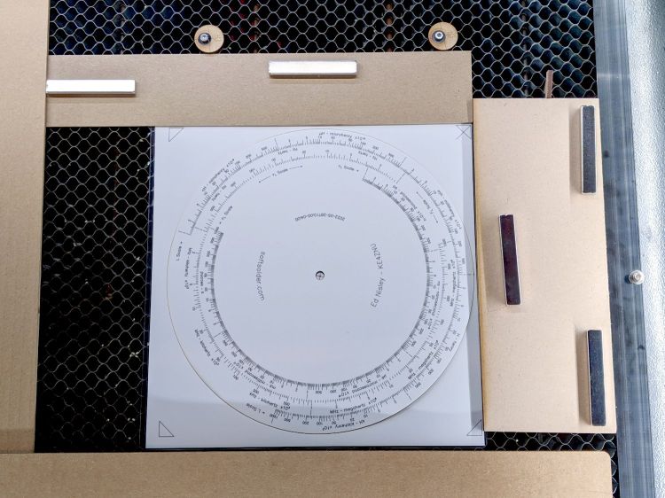
Lay some pieces atop an acetate sheet (to prevent scratching) on the scanner, grab the whole thing, then isolate an interesting chunk:
Next time: flip the image left-to-right to match the glass piece as seen from the top, because the scanner was looking at the bottom.
The weird purple background started as black, but blowing out the contrast while ignoring the color mis-correction makes the next step easier.
Trace around the perimeter with Scissors Select, clean up the result in Quick Mask mode, expand the selection by a few pixels to improve clearance, then turn it into a two-color image mask:

Import the mask into Lightburn, trace it into vector paths (which is trivially easy and accurate given such a high-contrast image), then cut a chipboard prototype to make sure it fits:

Clean up any misfits, test as needed, cut the inner shape and outer perimeter from 1.5 mm black acrylic, cut just the outer perimeter from 3 mm clear acrylic. Put the piece of black acrylic matching the glass shape into the scrap box.
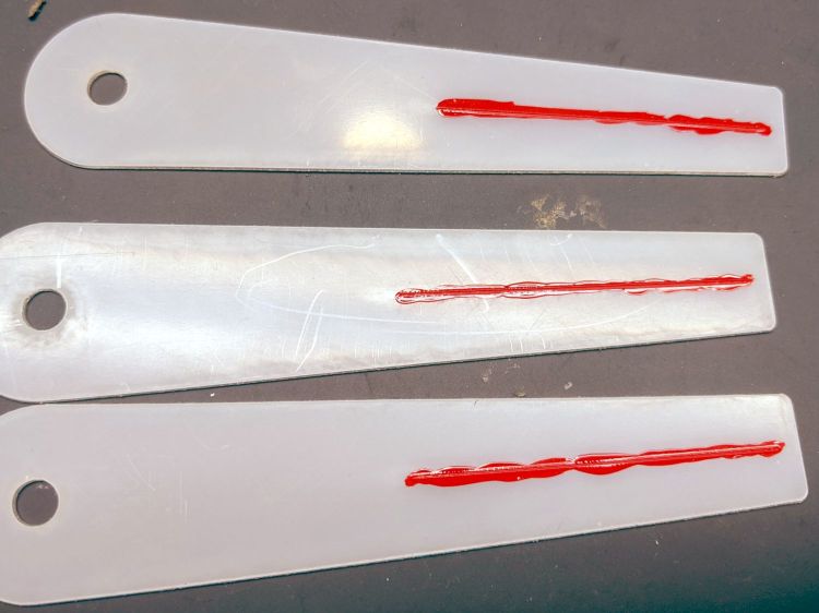
Mix up a few milliliters of clear pourable epoxy, butter up the clear acrylic, lay the black acrylic on top, line up the edges, then gently place the shattered glass into the cutout:

Next time: apply gentle pressure, perhaps through a flexy sheet, to ensure the entire glass surface contacts the epoxy layer while squeezing out the bubbles. This will surely skate the glass across the acrylic, so don’t leave it unsupervised.
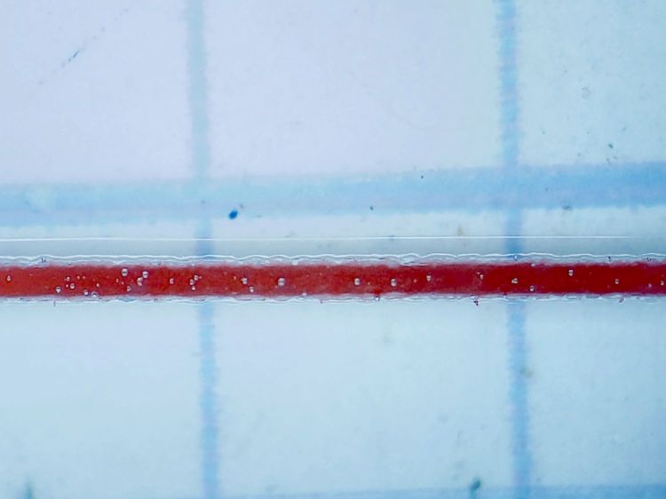
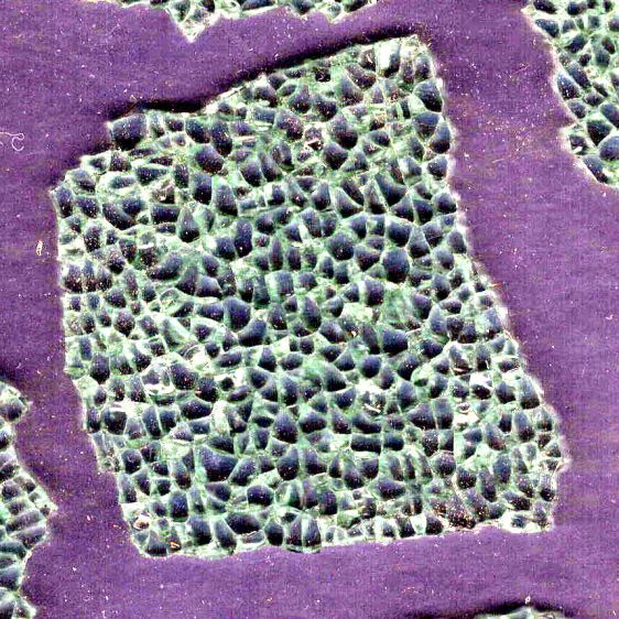
The relatively clear areas show where epoxy eased its way into the cracks between the granules; there is no correlation between the air bubbles and unfilled cracks. The epoxy had the viscosity of warm honey and I didn’t expect it to flow so easily, but it doesn’t affect the outcome.
Wait for a day, no matter how hard that may seem, for the epoxy to cure. Leave the small cup holding the remnants of the mixed epoxy nearby so you can test the cure without disturbing the Main Event.
The bottom looks pretty much like the top:

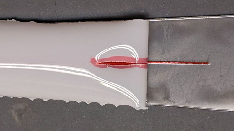
The shattered edge reflects off the bottom of the clear acrylic, as seen through the side:

Matching the perimeter to the fragment would be interesting, despite my low-vertex-polygon fixation.
It could become a paperweight or a (shot glass) coaster.