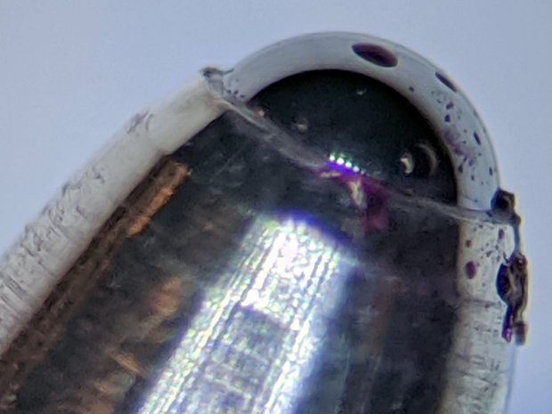
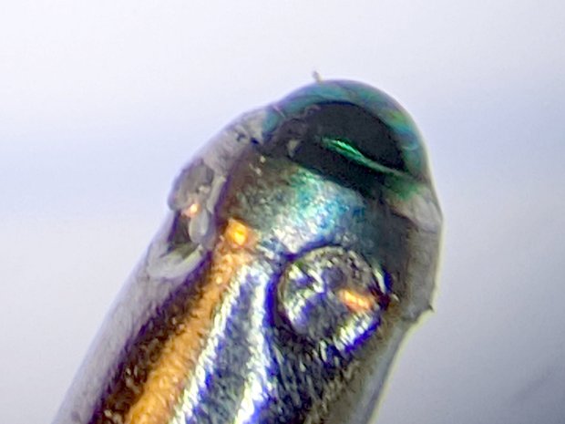
The first pass at cutting laminated decks for the Homage Tektronix Circuit Computer left little uncut snippets at the starting point of the cut. The point of the drag knife blade trundles along behind the cutting edge and, when the ending point equals the starting point, leaves an un-cut sliver as it’s retracted vertically:

The knife blade isn’t aligned in any particular direction, so it can leave a nick on either side as it enters the deck vertically at the start of the cut.
Gradually entering the deck along the cut line gives the blade enough time to swivel around to the proper alignment before it gets down to serious cutting. Continuing the final cut past the starting point then allows the blade to recut anything remaining from the entry move.
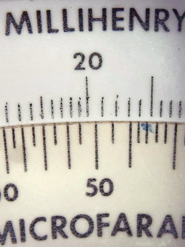
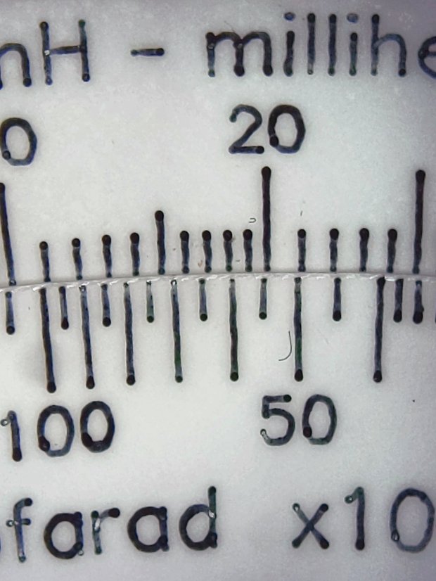
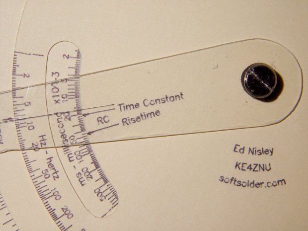
The middle and top decks have windows exposing the scales:
The paths are basically two arcs connected by semicircular cuts, but with ramps on each end recutting the entry and exit paths:

The entry path in the upper left slants downward from the TravelZ level of 1.5 (-ish) mm to Z=0, with the nose of the blade holder flush against the surface and the blade sunk to its full length. The vertical path to Z=-2 (-ish) increases the cutting pressure from roughly the preload value to preload + 2*(spring rate), so the blade won’t ride up under the cutting forces.
The path then goes completely around the window at Z=-2, then ramps up to the TravelZ level again.
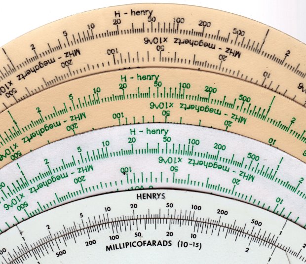
All of which produces a neat cutout that sticks to the Cricut mat when I peel the rest of the deck off:
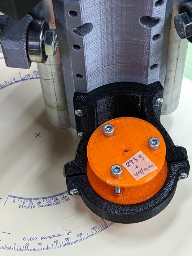
That’s a middle deck before I started laminating them, but you get the general idea.
The GCMC code (extracted from the complete lump) looks like this:
  local WindowArc = 54deg;

  local ac = -17 * ScaleArc + ScaleRT/2;   // center of window arc
  local r0 = DeckRad - ScaleHeight;        // outer
  local r1 = DeckRad - 2 * ScaleHeight;    // inner

  local aw = WindowArc - to_deg(atan(ScaleHeight,(r0 + r1)/2));    // window arc minus endcaps

  p0 = r0 * [cos(ac + aw/2),sin(ac + aw/2),-];
  p1 = r0 * [cos(ac - aw/2),sin(ac - aw/2),-];
  local p2 = r1 * [cos(ac - aw/2),sin(ac - aw/2),-];
  local p3 = r1 * [cos(ac + aw/2),sin(ac + aw/2),-];

  goto(p3);
  arc_cw(p0 +| [-,-,0],ScaleHeight/2);    // blade enters surface
  move([-,-,KnifeZ]);                     // apply pressure

  arc_cw(p1,r0);                          // smallest arc
  arc_cw(p2,ScaleHeight/2);               // half a circle
  arc_ccw(p3,r1);
  arc_cw(p0,ScaleHeight/2);

  arc_cw(p1 +| [-,-,TravelZ],r0);         // exit from cut

  goto([0,0,-]);
  goto([-,-,SafeZ]);
Having measured the angular position of the window and its size on the original Tek CC, I compute the coordinates of the four points where the semicircular “end caps” meet the longer arcs, then connect the dots with arc_xx() functions to generate the G-Code commands. As always, using the proper radius signs requires trial & error.
While I was at it, I added entry & exit moves for the deck’s central pivot hole and outer perimeter.
I’m pretty sure the right CAM package would take care of that, but GCMC operates well below the CAM level.