While adding the usual Reset button to a Raspberry Pi destined for a Show-n-Tell with the HP 7475A plotter, I browsed through the latest dtoverlay README and found this welcome surprise:
Name:   gpio-shutdown
Info:   Initiates a shutdown when GPIO pin changes. The given GPIO pin
        is configured as an input key that generates KEY_POWER events.
        This event is handled by systemd-logind by initiating a
        shutdown. Systemd versions older than 225 need an udev rule
        enable listening to the input device:

                ACTION!="REMOVE", SUBSYSTEM=="input", KERNEL=="event*", \
                        SUBSYSTEMS=="platform", DRIVERS=="gpio-keys", \
                        ATTRS{keys}=="116", TAG+="power-switch"

        This overlay only handles shutdown. After shutdown, the system
        can be powered up again by driving GPIO3 low. The default
        configuration uses GPIO3 with a pullup, so if you connect a
        button between GPIO3 and GND (pin 5 and 6 on the 40-pin header),
        you get a shutdown and power-up button.
Load:   dtoverlay=gpio-shutdown,<param>=<val>
Params: gpio_pin                GPIO pin to trigger on (default 3)

        active_low              When this is 1 (active low), a falling
                                edge generates a key down event and a
                                rising edge generates a key up event.
                                When this is 0 (active high), this is
                                reversed. The default is 1 (active low).

        gpio_pull               Desired pull-up/down state (off, down, up)
                                Default is "up".

                                Note that the default pin (GPIO3) has an
                                external pullup.

        debounce                Specify the debounce interval in milliseconds
                                (default 100)
So I added two lines to /boot/config.txt:
dtoverlay=gpio-shutdown
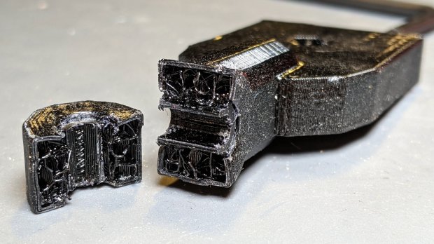
dtparam=act_led_trigger=heartbeatThe fancy “Moster heatsink” case doesn’t leave much room for wiring:
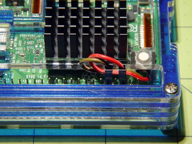
The switch button is slightly shorter than the acrylic sheet, so it’s recessed below the surface and requires a definite push to activate. It’s not as if it’ll get nudged by accident, but ya never know.
I’ll eventually migrate this change to all the RPi boxes around the house, because it just makes more sense than any of the alternatives. Heck, it’ll free up a key on the streaming radio player keypads, although I must move the I²C display to Bus 0 to avoid contention on Pin 3.
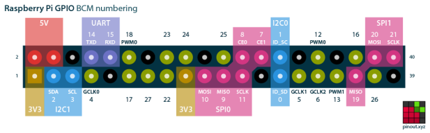
For reference, the Raspberry Pi header pinout:
I don’t know if I²C Bus 0 has the same 1.8 kΩ pullups as Bus 1, though; a look at the bus currents will be in order.