Our morning task on clear days has been clearing a forsythia overgrowth along the north lot line; the branches tip-root as our neighbor’s bushes creep southward toward the sunlight. The process involves ramming a six-foot octagonal high-carbon / tempered / tougher than nails / rings like a bell steel bar (measuring a generous 1-1/8 across the flats) deep into the dirt under the plant, kicking a 4×4 inch block against the bar, pushing downward with all my weight to pry the plant upward until something deep underground rips, then repeating from all directions until enough big roots break and the mass tears out:

Then it’s on to the next plant.
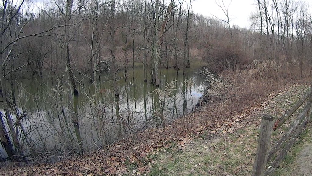
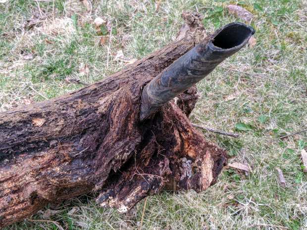
The turmoil exposed a run of black PVC pipe along the lot line, although one end seemed firmly anchored. More excavation revealed a giant grape vine root growing around the pipe:
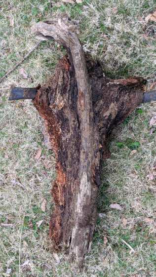
I had to sever the pipe with an axe on both sides to free the root:
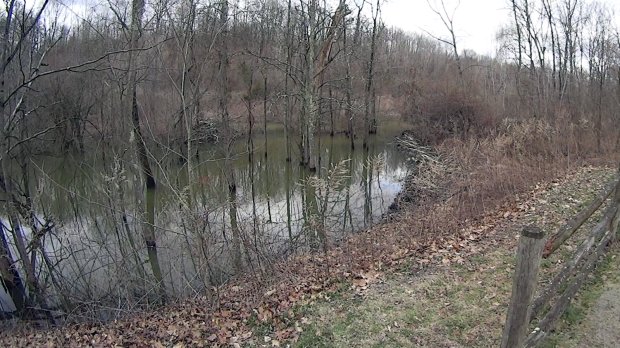
The pipe originally carried water from the Mighty Wappinger Creek along the east lot line, 500 feet away and 70-ish feet down, presumably to water the previous owner’s plants. As far as I’m concerned, the remains of that pump will remain on the bottomlands forevermore, but at least we’ve cleared the remains of the plumbing.
Mornings like that make writing CNC code look downright attractive, but I’m developing the cutest little biceps …