|
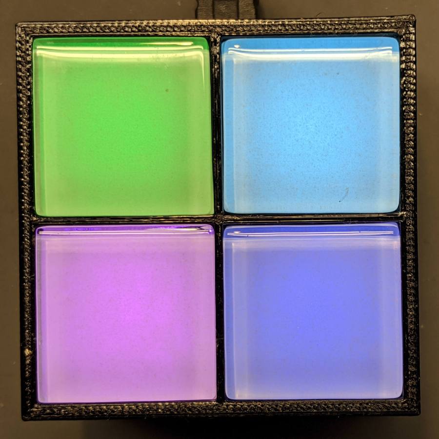
// Illuminated Tile Grid |
|
// Ed Nisley – KE4ZNU |
|
// 2020-05 |
|
|
|
/* [Configuration] */ |
|
|
|
Layout = "Build"; // [Cell,CellArray,MCU,Base,Show,Build] |
|
|
|
Shape = "Square"; // [Square, Pyramid, Cone] |
|
|
|
Cells = [2,2]; |
|
|
|
CellDepth = 15.0; |
|
|
|
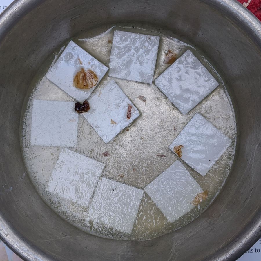
Inserts = true; |
|
|
|
SupportInserts = true; |
|
|
|
/* [Hidden] */ |
|
|
|
ThreadThick = 0.25; |
|
ThreadWidth = 0.40; |
|
|
|
HoleWindage = 0.2; |
|
|
|
function IntegerMultiple(Size,Unit) = Unit * ceil(Size / Unit); |
|
|
|
Protrusion = 0.1; // make holes end cleanly |
|
|
|
ID = 0; |
|
OD = 1; |
|
LENGTH = 2; |
|
|
|
Tile = [25.0 + 0.1,25.0 + 0.1,4.0]; |
|
|
|
WallThick = 4*ThreadWidth; |
|
FloorThick = 3.0; |
|
|
|
Flange = [2*ThreadWidth,2*ThreadWidth,0]; // ridge supporting tile |
|
|
|
Separator = [3*ThreadWidth,3*ThreadWidth,Tile.z – 1]; // between tiles |
|
|
|
Screw = [3.0,6.0,3.5]; // M3 SHCS, OD=head, LENGTH=head |
|
Insert = [3.0,4.2,8.0]; // threaded brass insert |
|
|
|
ScrewRecess = Screw[LENGTH] + 4*ThreadThick; |
|
|
|
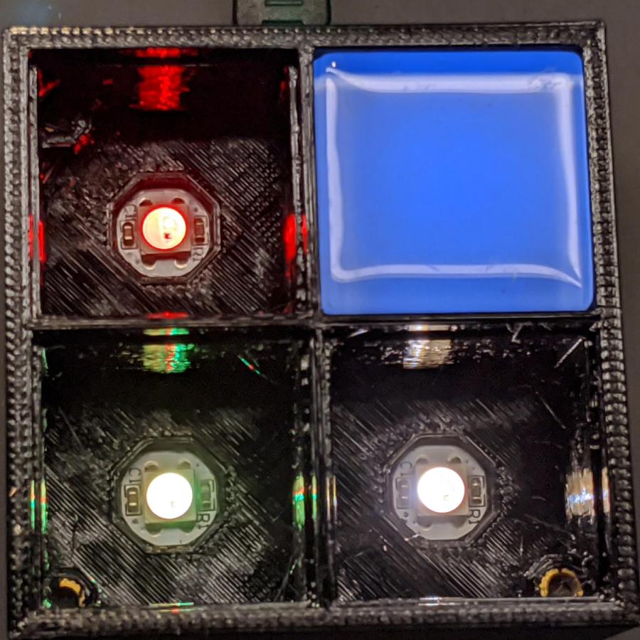
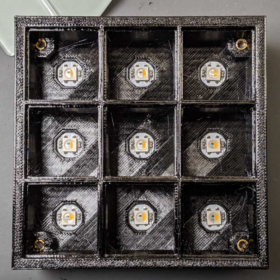
LEDPCB = [9.6,9.6,2.9]; // round SK6812, squared-off sides |
|
|
|
LED = [5.0 + 2*HoleWindage,5.0 + 2*HoleWindage,1.3]; |
|
|
|
LEDOffset = [0.0,0.0,0.0]; // if offset from PCB center |
|
|
|
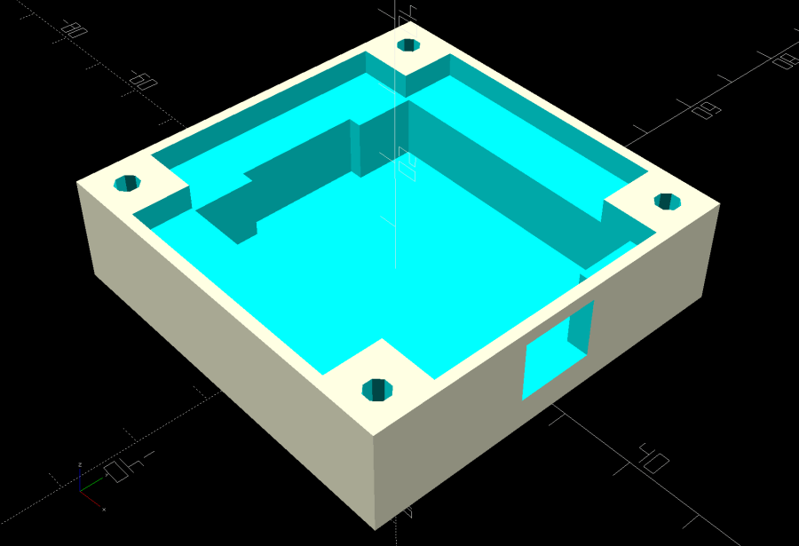
CellOAL = [Tile.x,Tile.y,0] + Separator + [0,0,CellDepth] + [0,0,FloorThick]; |
|
|
|
ArrayOAL = [Cells.x*CellOAL.x,Cells.y*CellOAL.y,CellOAL.z]; // just the LED cells |
|
|
|
BlockOAL = ArrayOAL + [2*WallThick,2*WallThick,0]; // LED cells + exterior wall |
|
echo(str("Block OAL: ",BlockOAL)); |
|
|
|
InsertOC = ArrayOAL – [Insert[OD],Insert[OD],0] – [WallThick,WallThick,0]; |
|
echo(str("Insert OC: ",InsertOC)); |
|
|
|
TapeThick = 1.0; |
|
|
|
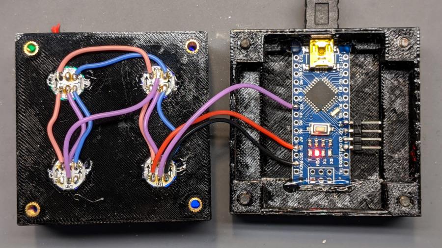
Arduino = [44.0,18.0,8.0 + TapeThick]; // Arduino Nano to top of USB Mini-B plug |
|
USBPlug = [15.0,11.0,9.0]; // USB Mini-B plug insulator |
|
USBOffset = [0,0,5.0]; // offset from PCB base |
|
|
|
WiringSpace = 3.5; |
|
WiringBay = [(Cells.x – 1)*CellOAL.x + LEDPCB.x,(Cells.y – 1)*CellOAL.y + LEDPCB.x,WiringSpace]; |
|
|
|
PlateOAL = [BlockOAL.x,BlockOAL.y,FloorThick + Arduino.z + WiringSpace]; // allow wiring above Arduino |
|
echo(str("Base Plate: ",PlateOAL)); |
|
|
|
echo(str("Screw length: ",(PlateOAL.z – ScrewRecess) + Insert.z/2," to ",(PlateOAL.z – ScrewRecess) + Insert.z)); |
|
|
|
LegendRecess = 1*ThreadThick; |
|
|
|
//———————— |
|
|
|
module PolyCyl(Dia,Height,ForceSides=0) { // based on nophead's polyholes |
|
Sides = (ForceSides != 0) ? ForceSides : (ceil(Dia) + 2); |
|
FixDia = Dia / cos(180/Sides); |
|
cylinder(d=(FixDia + HoleWindage),h=Height,$fn=Sides); |
|
} |
|
|
|
|
|
//———————– |
|
// Base and optics in single tile |
|
|
|
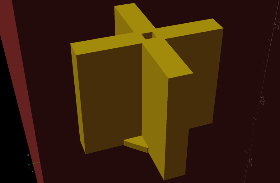
module LEDCone() { |
|
|
|
hull() { |
|
translate([0,0,CellDepth + Tile.z/2]) |
|
cube(Tile – 2*[Flange.x,Flange.y,0],center=true); |
|
|
|
if (Shape == "Square") { |
|
translate([0,0,LEDPCB.z/2]) |
|
cube([Tile.x,Tile.y,LEDPCB.z] – 2*[Flange.x,Flange.y,0],center=true); |
|
} |
|
else if (Shape == "Pyramid") { |
|
translate([0,0,LEDPCB.z/2]) |
|
cube(LEDPCB,center=true); |
|
} |
|
else if (Shape == "Cone") { |
|
translate([0,0,LEDPCB.z/2]) |
|
cylinder(d=1.0*LEDPCB.x,h=LED.z,center=true); |
|
} |
|
else { |
|
echo(str("Whoopsie! Invalid Shape: ",Shape)); |
|
cube(5); |
|
} |
|
} |
|
} |
|
|
|
// One complete LED cell |
|
|
|
module LEDCell() { |
|
|
|
difference() { |
|
|
|
translate([0,0,CellOAL.z/2]) |
|
cube(CellOAL + [Protrusion,Protrusion,0],center=true); // force overlapping adjacent sides! |
|
|
|
translate([0,0,CellOAL.z – Separator.z + Tile.z/2]) |
|
cube(Tile,center=true); |
|
|
|
translate([0,0,LEDPCB.z]) |
|
LEDCone(); |
|
|
|
// cube([LED.x,LED.y,CellOAL.z],center=true); |
|
|
|
translate(-LEDOffset + [0,0,-CellOAL.z/2]) |
|
rotate(180/8) |
|
PolyCyl(LEDPCB.x,CellOAL.z,8); |
|
} |
|
|
|
} |
|
|
|
// The whole array of cells |
|
|
|
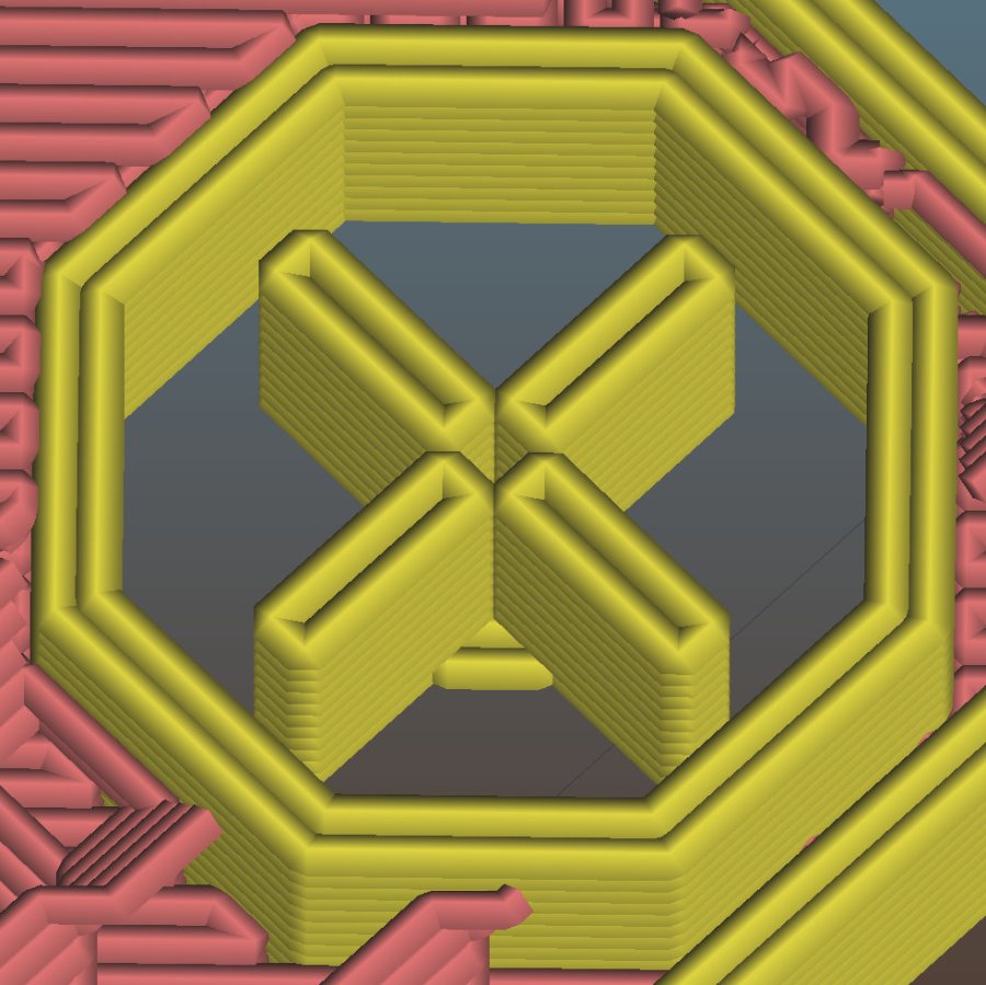
module CellArray() { |
|
difference() { |
|
union() { |
|
translate([CellOAL.x/2 – Cells.x*CellOAL.x/2,CellOAL.y/2 – Cells.y*CellOAL.y/2,0]) |
|
for (i=[0:Cells.x – 1], j=[0:Cells.y – 1]) |
|
translate([i*CellOAL.x,j*CellOAL.y,0]) |
|
LEDCell(); |
|
if (Inserts) // bosses |
|
for (i=[-1,1], j=[-1,1]) |
|
translate([i*InsertOC.x/2,j*InsertOC.y/2,0]) |
|
rotate(180/8) |
|
cylinder(d=Insert[OD] + 2*WallThick,h=Insert[LENGTH],$fn=8); |
|
} |
|
if (Inserts) // holes |
|
for (i=[-1,1], j=[-1,1]) |
|
translate([i*InsertOC.x/2,j*InsertOC.y/2,-Protrusion]) |
|
rotate(180/8) |
|
PolyCyl(Insert[OD],Insert[LENGTH] + FloorThick + Protrusion,8); |
|
|
|
} |
|
|
|
difference() { |
|
translate([0,0,CellOAL.z/2]) |
|
cube(BlockOAL,center=true); |
|
translate([0,0,CellOAL.z]) |
|
cube(ArrayOAL + [0,0,2*CellOAL.z],center=true); |
|
|
|
} |
|
} |
|
|
|
// Arduino bounding box |
|
// Origin at center bottom of PCB |
|
|
|
module Controller() { |
|
union() { |
|
translate([0,0,Arduino.z/2]) |
|
cube(Arduino,center=true); |
|
translate([Arduino.x/2 – Protrusion,-USBPlug.y/2,USBOffset.z + TapeThick – USBPlug.z/2]) |
|
cube(USBPlug + [Protrusion,0,0],center=false); |
|
} |
|
} |
|
|
|
// Baseplate |
|
|
|
module BasePlate() { |
|
|
|
difference() { |
|
translate([0,0,PlateOAL.z/2]) |
|
cube(PlateOAL,center=true); |
|
|
|
translate([PlateOAL.x/2 – Arduino.x/2 – 2*WallThick,0,FloorThick]) |
|
Controller(); |
|
|
|
translate([PlateOAL.x/2 – Arduino.x/2 – 2*WallThick,0,FloorThick + PlateOAL.z/2]) |
|
cube([Arduino.x – 2*2.0,WiringBay.y,PlateOAL.z],center=true); // cutouts beside MCU |
|
|
|
translate([0,0,PlateOAL.z – WiringBay.z + PlateOAL.z/2 – Protrusion]) |
|
cube([PlateOAL.x – 2*WallThick,WiringBay.y,PlateOAL.z],center=true); // cutout above MCU |
|
translate([0,0,PlateOAL.z – WiringBay.z + PlateOAL.z/2 – Protrusion]) |
|
cube([WiringBay.x,PlateOAL.y – 2*WallThick,PlateOAL.z],center=true); // cutout above MCU |
|
|
|
|
|
if (Inserts) |
|
for (i=[-1,1], j=[-1,1]) |
|
translate([i*InsertOC.x/2,j*InsertOC.y/2,-Protrusion]) |
|
rotate(180/8) { |
|
PolyCyl(Screw[ID],2*PlateOAL.z,8); |
|
PolyCyl(Screw[OD],ScrewRecess + Protrusion,8); |
|
} |
|
|
|
cube([45,17.0,2*LegendRecess],center=true); |
|
} |
|
|
|
linear_extrude(height=2*LegendRecess) { |
|
translate([0,1]) |
|
rotate(-0*90) mirror([1,0,0]) |
|
text(text="Ed Nisley",size=6,font="Arial:style:Bold",halign="center"); |
|
translate([0,-6.5]) |
|
rotate(-0*90) mirror([1,0,0]) |
|
text(text="softsolder.com",size=4.5,font="Arial:style:Bold",halign="center"); |
|
} |
|
|
|
Fin = [Screw[OD]/2 – 1.5*ThreadWidth,2*ThreadWidth,ScrewRecess – ThreadThick]; |
|
if (Inserts && SupportInserts) |
|
color("Yellow") |
|
for (i=[-1,1], j=[-1,1]) |
|
translate([i*InsertOC.x/2,j*InsertOC.y/2,0]) { |
|
rotate(180/8) |
|
cylinder(d=6*ThreadWidth,h=ThreadThick,$fn=8); |
|
for (a=[0:90:360]) |
|
rotate(a) |
|
translate([Fin.x/2 + ThreadWidth/2,0,(ScrewRecess – ThreadThick)/2]) |
|
cube(Fin,center=true); |
|
} |
|
} |
|
|
|
|
|
//———————– |
|
// Build things |
|
|
|
if (Layout == "Cell") |
|
LEDCell(); |
|
|
|
else if (Layout == "CellArray") |
|
CellArray(); |
|
|
|
else if (Layout == "MCU") |
|
Controller(); |
|
|
|
else if (Layout == "Base") |
|
BasePlate(); |
|
|
|
else if (Layout == "Show") { |
|
translate([0,0,3*PlateOAL.z]) |
|
CellArray(); |
|
BasePlate(); |
|
translate([PlateOAL.x/2 – Arduino.x/2 – 2*WallThick,0,FloorThick]) |
|
color("Orange",0.3) |
|
Controller(); |
|
} |
|
|
|
else if (Layout == "Build") union() { |
|
translate([0,0.6*BlockOAL.y,0]) |
|
CellArray(); |
|
translate([0,-0.6*BlockOAL.x,0]) |
|
rotate(90) |
|
BasePlate(); |
|
} |
|
|