Ed Nisley's Blog: Shop notes, electronics, firmware, machinery, 3D printing, laser cuttery, and curiosities. Contents: 100% human thinking, 0% AI slop.
Tag: Improvements
Making the world a better place, one piece at a time
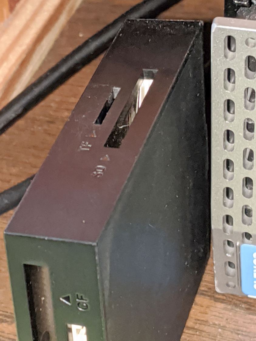
Consumer electronics designers seem to favor low- or no-contrast markings, with this USB reader falling on the vanishing end of the spectrum:
USB card reader – low-contrast slots
I poke the MicroSD card from the AS30V helmet camera into the smaller slot on the top surface, but, contrary to what’s revealed by the camera’s flash, the slot is a black-on-black target.
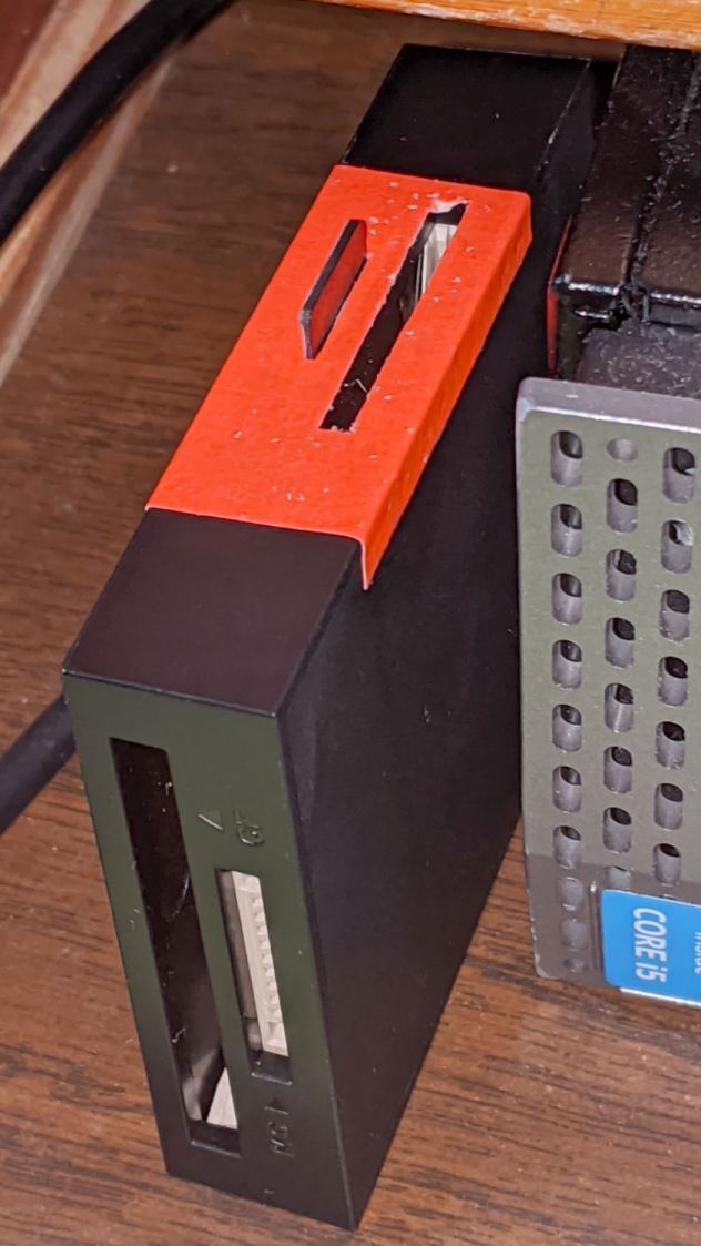
Well, I finally fixed that:
USB card reader – high-contrast slots
Although white tape surely would have sufficed, the roll of fluorescent red came to hand and that’s what it’ll be. The CompactFlash and Memory Stick slots on the front don’t see much traffic and have better access.
I slapped tape on case, trimmed the slots with a razor knife, and declared victory.
A Round Tuit™ finally arrived for this long-delayed project:
Vise soft jaws – installed
They’re bandsawed from an impossibly heavy-duty U-shaped aluminum extrusion salvaged from a scrap pile; the flanges are 6 and 7 mm thick. I’ll put in a good word for the Proxxon 10/14 TPI blade, because it goes through aluminum plate like butter.
The wood strip under the top flange raises the fillet on the interior angle enough to let the extrusion sit flat on the top vise jaw and square against the gripping side. It’s held in place with double-sided carpet tape.
They’re faced with a rubber sheet I thought was twice as thick when I picked it out of the Big Box o’ Squishy Sheets, but turned out to be two thinner sheets invisibly stuck together. Carpet tape holds one of the sheets to the jaw; I expect the other sheet to fall off in short order.
You’re supposed to embed neodymium magnets in the jaws to hold them to the vise. As far as I can tell, they’re perfectly happy to just sit there all by themselves and, anyway, magnets would grow lethally sharp and bulky steel fur coats in short order.
Squaring the long edge didn’t pose much of a problem:
Vise soft jaws – squaring edge
Tidying the ends, however, required more setup:
Vise soft jaws – squaring ends
That’s the Sherline Tilting Angle Plate at 90°, with barely enough room on the far side for the base of a Starrett Double Square to set the extrusion vertical; the hand clamp holds it in place while tightening the step clamps. It sits on an aluminum sheet to put its upper end three smidgens over the angle plate, letting me flycut one smidgen for a clean edge.
Now I can retire the old soft jaws, which have served for too many decades and are far too ugly to show; improvised from weatherstripping glued to bent-square copper pipe and intended as a quick fix. You know how that goes …
Just for completeness, here’s what the various soaker hose clamps look like in the garden, as solid models only let you visualize the ideal situation:
Soaker Hose Connector Clamp – Show view
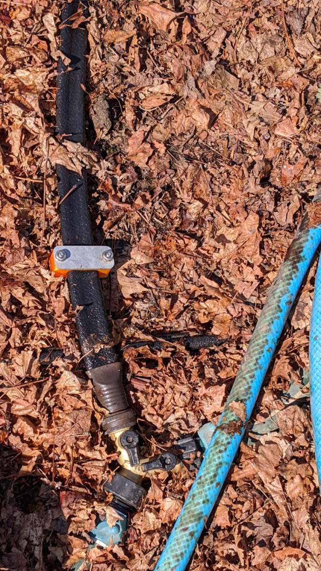
This one prevents a puddle in the path to the right:
Soaker hose repairs in situ – clamp
Bending the hoses around the end of a bed puts them on edge, with this clamp suppressing a shin-soaking spray to the left:
Soaker hose repairs in situ – end-on clamp
The clamp at the connector closes a leak around the crimped brass fitting, with the other two preventing gouges from direct sprays into the path along the bottom of the picture:
Soaker hose repairs in situ – clamps and connector fix
All in all, a definite UI improvement!
As far as I can tell, we have the only soaker hose repairs & spritz stoppers in existence. Hooray for 3D printing!
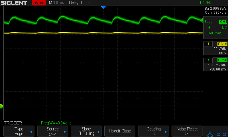
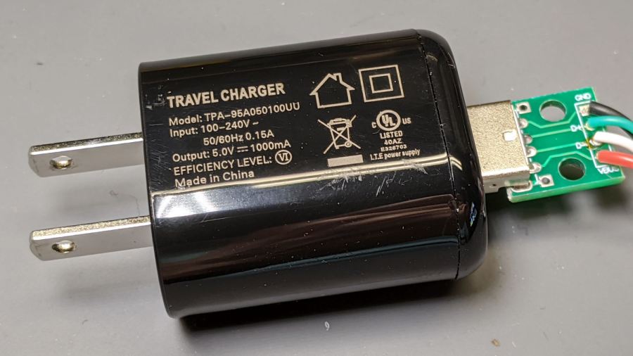
The voltage (yellow) and current (green, 100 mA/div) waveforms look downright tame compared to some of the other chargers!
I made a cursory attempt to crack the case open, but gave up before doing any permanent damage. Hey, that UL listing (and, presumably, the interior details) means they’re three times the price of those Anonymous chargers!
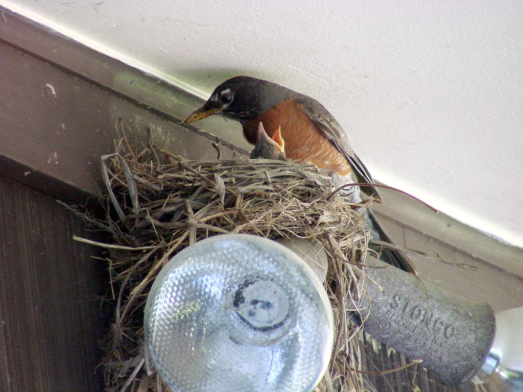
Nothing prizewinning, but better than no picture at all:
Garage Robin – recovered image
Note that you start by copying a reasonable chunk of the partition from the Memory Stick / (micro)SD Card first, to prevent a bad situation from getting worse.
Now I can remember the easy way the next time around this block …
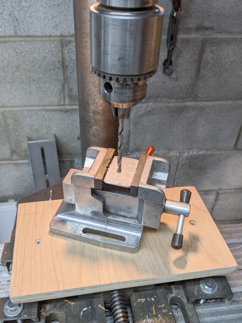
I built a small plywood work table for the drill press:
Drill press – scarred vise table
Obviously, that was a long time ago. It’s a plywood scrap with a small cleat screwed to its bottom, upon which one can position / clamp / hold / finagle smallish workpieces without worrying about drilling into the surface.
The mill vise under the plywood grips the cleat and the whole affair rides on a Sears “Drill Press Milling Attachment Stock No 27585” which is basically a simple XY table with hand dials. It’s not rigid enough for actual milling (which you should never do on a drill press, anyway, because the end mill will pull itself out of the Jacobs chuck), but it’s good for tweaking the position before you drill something.
One should never hand-hold workpieces while drilling.
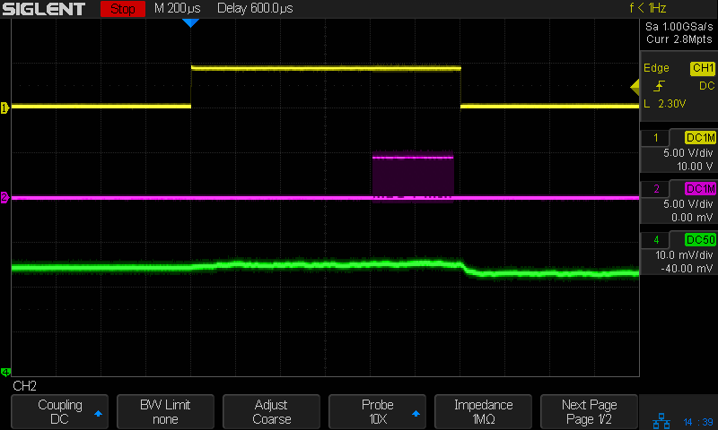
So I can see the actual current waveform of a Glass Tile box running from a bench power supply:
Tiles 2×2 – bench supply – 50 mA-div
The top trace is the firmware heartbeat from the Arduino Nano, the middle trace is the SK6812 LED data stream, and the bottom trace is the USB current at 50 mA/div. The current steps downward by about 10 mA (just after the data burst) when one of the tiles changes color and and LED shuts off.
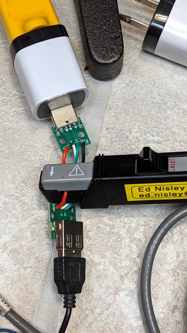
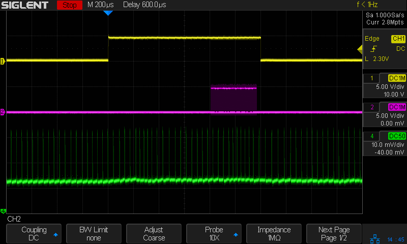
The current probe reveals some mysteries, such as this waveform from a dirt-cheap USB charger:
Tiles 2×2 – anon white charger – 50 mA-div
I wonder why it’s ramming 100 mA current spikes into the circuit, too. At least now I can see what’s going on.