I’ve been putting this type of support structure inside screw holes & suchlike for years:

It’s basically a group of small rectangles rotated around the hole’s axis and about one thread thickness shorter than the overhanging interior.
I’ve found that incorporating exactly the right support structure eliminates Slic3r’s weird growths, eases removal, and generally works better all around.
So doing this for the baseplate of the Glass Tile frame came naturally:

This OpenSCAD snippet plunks one of those asterisks in each of four screw holes:
  if (Support)
    color("Yellow")
      for (i=[-1,1], j=[-1,1])
        translate([i*InsertOC.x/2,j*InsertOC.y/2,0])
          for (a=[0:45:135])
              rotate(a)
                translate([0,0,(Screw[LENGTH] - ThreadThick)/2])
                  cube([Screw[OD] - 2*ThreadWidth,2*ThreadWidth,Screw[LENGTH] - ThreadThick],center=true);
The “cubes” overlap in the middle, with no completely coincident faces or common edges, so it’s 2-manifold. Slic3r, however, produces a weird time estimate whenever the model includes those structures:
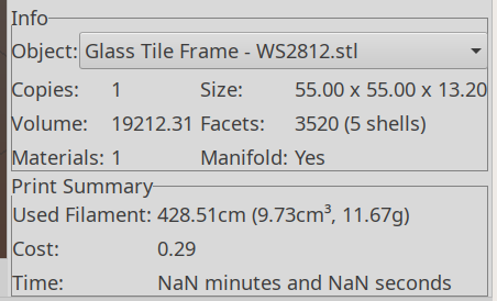
NaN stands for Not A Number and means something horrible has happened in the G-Code generation. Fortunately, the G-Code worked perfectly and produced the desired result, but I’m always uneasy when Something Seems Wrong.
Messing around with the code produced a slightly different support structure:
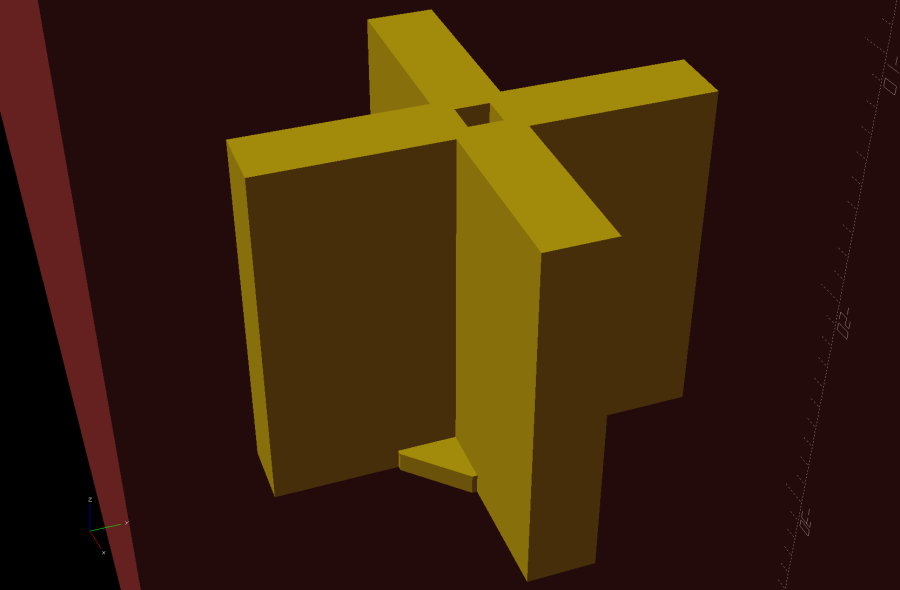
The one thread thick square on the bottom helps glue the structure to the platform and four ribs work just as well as eight in the octagonal hole:
  Fin = [Screw[OD]/2 - 1.5*ThreadWidth,2*ThreadWidth,ScrewRecess - ThreadThick];
  if (Inserts && SupportInserts)
    color("Yellow")
      for (i=[-1,1], j=[-1,1])
        translate([i*InsertOC.x/2,j*InsertOC.y/2,0]) {
          rotate(180/8)
            cylinder(d=6*ThreadWidth,h=ThreadThick,$fn=8);
          for (a=[0:90:360])
              rotate(a)
                translate([Fin.x/2 + ThreadWidth/2,0,(ScrewRecess - ThreadThick)/2])
                  cube(Fin,center=true);
        }
Which changed the NaN time estimates into actual numbers.
One key difference may be the small hole in the middle. The four ribs (not two!) now overlap by one thread width around the hole, so they’re not quite coincident and Slic3r produces a tidy model:
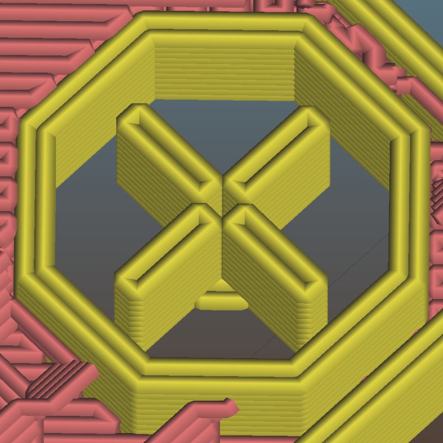
The hole eliminates a smear of infill from the center, which may have something to do with the improvement.
In any event, I have an improved copypasta recipe for the next screw holes in need of support, even if I don’t understand why it’s better.

Comments
2 responses to “Solid Modeling: Support Puzzle”
Glancing at the code, it looks to me as though the top and bottom faces are coincident across all the “cubes.” That’s been enough to generate non-manifold geometry for me, if I’m not misreading this.
I’ve resorted to either making all of them taller and sitting lower than I want and intersecting the set of them with a bounding box to trim them to the coincident faces I want after the implicit union, or translating each one “fudge” (or epsilon) higher on the Z axis than the previous, with fudge typically = 0.001.
The dead-simple asterisk geometry “used to work”, even with all its same-plane faces, so something’s new & different. I think the recent OpenSCAD commit enabling lazy unions (which option, of course, I immediately turned on) makes the
forloop return a bunch of non-unioned slabs that gum up my simple assumptions.The Right Way now is probably to build the asterisk from 2D
squares,linear_extrudethe resulting shape to the proper height, then add the footer disk. I’ll try (to remember) that the next time it doesn’t work …