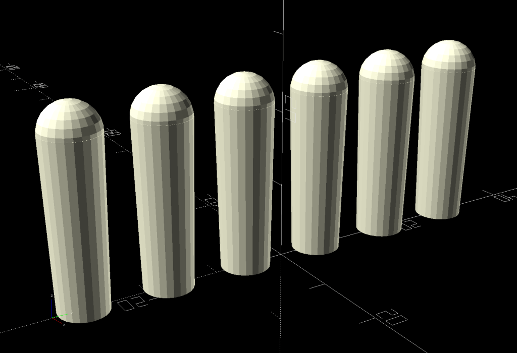
Although I’d put the same knob on the half-triangle end piece template as on the equilateral triangle template for piecing hexagons into strips, Mary decided a flat chip would be easier to use:
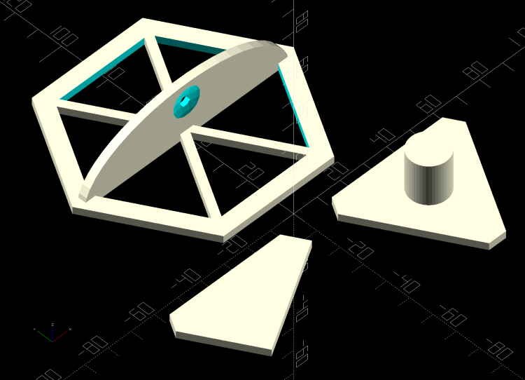
Bonus: you can now flip it over to cut the other half-triangles, if you haven’t already figured out how to cut two layers of fabric folded wrong sides together.
While I was at it, the knob on the triangle became optional, too. Flipping that one doesn’t buy you much, though.
The OpenSCAD source as a GitHub Gist has been ever so slightly tweaked:
This file contains hidden or bidirectional Unicode text that may be interpreted or compiled differently than what appears below. To review, open the file in an editor that reveals hidden Unicode characters.
Learn more about bidirectional Unicode characters
| // Quilting – Hexagon Templates | |
| // Ed Nisley KE4ZNU – July 2020 | |
| // Reverse-engineered to repair a not-quite-standard hexagon quilt | |
| // Useful geometry: | |
| // https://en.wikipedia.org/wiki/Hexagon | |
| /* [Layout Options] */ | |
| Layout = "Build"; // [Build, HexBuild, HexPlate, TriBuild, TriPlate, EndBuild, EndPlate] | |
| //——- | |
| //- Extrusion parameters must match reality! | |
| // Print with 2 shells | |
| /* [Hidden] */ | |
| ThreadThick = 0.25; | |
| ThreadWidth = 0.40; | |
| HoleFinagle = 0.2; | |
| HoleFudge = 1.00; | |
| function HoleAdjust(Diameter) = HoleFudge*Diameter + HoleFinagle; | |
| Protrusion = 0.1; // make holes end cleanly | |
| function IntegerMultiple(Size,Unit) = Unit * ceil(Size / Unit); | |
| inch = 25.4; | |
| //——- | |
| // Dimensions | |
| /* [Layout Options] */ | |
| FinishedWidthInch = 2.75; | |
| FinishedWidth = FinishedWidthInch * inch; | |
| SeamAllowanceInch = 0.25; | |
| SeamAllowance = SeamAllowanceInch * inch; | |
| TemplateThick = 3.0; | |
| TriKnob = true; | |
| EndKnob = false; | |
| /* [Hidden] */ | |
| FinishedSideInch = FinishedWidthInch/sqrt(3); | |
| FinishedSide = FinishedSideInch * inch; | |
| echo(str("Finished side: ",FinishedSideInch," inch")); | |
| CutWidth = FinishedWidth + 2*SeamAllowance; | |
| CutSide = CutWidth/sqrt(3); | |
| echo(str("Cut side: ",CutSide / inch," inch")); | |
| // Make polygon-circles circumscribe the target widths | |
| TemplateID = FinishedWidth / cos(180/6); | |
| TemplateOD = CutWidth / cos(180/6); | |
| /* [Hidden] */ | |
| TriRadius = FinishedSide/sqrt(3); | |
| TriPoints = [[TriRadius,0], | |
| [TriRadius*cos(120),TriRadius*sin(120)], | |
| [TriRadius*cos(240),TriRadius*sin(240)] | |
| ]; | |
| echo(str("TriPoints: ",TriPoints)); | |
| EndPoints = [[TriRadius,0], | |
| [TriRadius*cos(120),TriRadius*sin(120)], | |
| [TriRadius*cos(120),0] | |
| ]; | |
| echo(str("EndPoints: ",EndPoints)); | |
| TipCutRadius = 2*(TriRadius + SeamAllowance); // circumscribing radius of tip cutter | |
| TipPoints = [[TipCutRadius,0], | |
| [TipCutRadius*cos(120),TipCutRadius*sin(120)], | |
| [TipCutRadius*cos(240),TipCutRadius*sin(240)] | |
| ]; | |
| HandleHeight = 1 * inch; | |
| HandleLength = (TemplateID + TemplateOD)/2; | |
| HandleThick = IntegerMultiple(3.0,ThreadWidth); | |
| HandleSides = 12*4; | |
| StringDia = 4.0; | |
| StringHeight = 0.6*HandleHeight; | |
| DentDepth = HandleThick/4; | |
| DentDia = 15 * DentDepth; | |
| DentSphereRadius = (pow(DentDepth,2) + pow(DentDia,2)/4)/(2*DentDepth); | |
| KnobOD = 15.0; // Triangle handle | |
| KnobHeight = 20.0; | |
| //——- | |
| module PolyCyl(Dia,Height,ForceSides=0) { // based on nophead's polyholes | |
| Sides = (ForceSides != 0) ? ForceSides : (ceil(Dia) + 2); | |
| FixDia = Dia / cos(180/Sides); | |
| cylinder(r=HoleAdjust(FixDia)/2,h=Height,$fn=Sides); | |
| } | |
| //——- | |
| // Hex template | |
| module HexPlate() { | |
| difference() { | |
| cylinder(r=TemplateOD/2,h=TemplateThick,$fn=6); | |
| translate([0,0,-Protrusion]) | |
| cylinder(r=TemplateID/2,h=(TemplateThick + 2*Protrusion),$fn=6); | |
| } | |
| for (i=[1:6/2]) | |
| rotate(i*60) | |
| translate([0,0,TemplateThick/2]) | |
| cube([HandleLength,HandleThick,TemplateThick],center=true); | |
| } | |
| module HexHandle() { | |
| difference() { | |
| rotate([90,0,0]) | |
| scale([1,HandleHeight/(TemplateOD/2),1]) | |
| rotate(180/HandleSides) | |
| cylinder(d=HandleLength,h=HandleThick,center=true,$fn=HandleSides); | |
| translate([0,0,-HandleHeight]) | |
| cube([2*TemplateOD,2*TemplateOD,2*HandleHeight],center=true); | |
| translate([0,HandleThick,StringHeight]) | |
| rotate([90,090,0]) | |
| rotate(180/8) | |
| PolyCyl(StringDia,2*HandleThick,8); | |
| for (j=[-1,1]) { | |
| translate([0,j*(DentSphereRadius + HandleThick/2 – DentDepth),StringHeight]) | |
| rotate(180/48) | |
| sphere(r=DentSphereRadius,$fn=48); | |
| } | |
| } | |
| } | |
| module HexTemplate() { | |
| HexPlate(); | |
| HexHandle(); | |
| } | |
| //——- | |
| // Triangle template | |
| module TriPlate() { | |
| linear_extrude(height=TemplateThick) | |
| intersection() { | |
| offset(delta=SeamAllowance) // basic cutting outline | |
| polygon(points=TriPoints); | |
| rotate(180) | |
| polygon(points=TipPoints); | |
| } | |
| } | |
| module TriTemplate() { | |
| union() { | |
| if (TriKnob) | |
| cylinder(d=KnobOD,h=KnobHeight,$fn=HandleSides); | |
| TriPlate(); | |
| } | |
| } | |
| //——- | |
| // End piece template | |
| module EndPlate() { | |
| linear_extrude(height=TemplateThick) | |
| intersection() { | |
| offset(delta=SeamAllowance) // basic cutting outline | |
| polygon(points=EndPoints); | |
| rotate(180) | |
| polygon(points=TipPoints); | |
| } | |
| } | |
| module EndTemplate() { | |
| union() { | |
| if (EndKnob) | |
| translate([0,(TriRadius/2)*sin(30),0]) | |
| cylinder(d=KnobOD,h=KnobHeight,$fn=HandleSides); | |
| EndPlate(); | |
| } | |
| } | |
| //——- | |
| // Build it! | |
| if (Layout == "HexPlate") | |
| HexPlate(); | |
| if (Layout == "HexBuild") | |
| HexTemplate(); | |
| if (Layout == "TriPlate") | |
| TriPlate(); | |
| if (Layout == "TriBuild") | |
| TriTemplate(); | |
| if (Layout == "EndPlate") | |
| EndPlate(); | |
| if (Layout == "EndBuild") | |
| EndTemplate(); | |
| if (Layout == "Build") { | |
| translate([1.5*TriRadius,-TriRadius,0]) | |
| rotate(180/6) | |
| TriTemplate(); | |
| translate([-1.5*TriRadius,-TriRadius,0]) | |
| rotate(180/6) | |
| EndTemplate(); | |
| translate([0,TemplateOD/2,0]) | |
| HexTemplate(); | |
| } |