Ed Nisley's Blog: Shop notes, electronics, firmware, machinery, 3D printing, laser cuttery, and curiosities. Contents: 100% human thinking, 0% AI slop.
Tag: Improvements
Making the world a better place, one piece at a time
Adding a bit of trim to the bottom of the LED spider makes it look better and helps keep the strut wires in place:
Astable Multivibrator – Alkaline – Radome trim
It’s obviously impossible to build like that, so it’s split across the middle of the strut:
Astable Multivibrator – Alkaline – Radome trim
Glue it together with black adhesive and a couple of clamps:
LED Spider – glue clamping
The aluminum fixtures (jigs?) are epoxied around snippets of strut wire aligning the spider parts:
LED Spider – gluing fixture
Those grossly oversized holes came pre-drilled in an otherwise suitable aluminum rod from the Little Tray o’ Cutoffs. I faced off the ends, chopped the rod in two, recessed the new ends, and declared victory. Might need better ones at some point, but they’ll do for now.
Next step: wire up an astable with a yellow LED to go with the green and blueboosted LEDs.
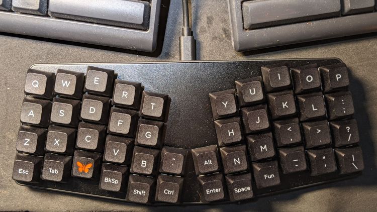
Having helped grossly over-fund the Atreus Kickstarter earlier this year, a small box arrived pretty much on-time:
Atreus keyboard – overview
I did get the blank keycap set, but have yet to screw up sufficient courage to install them. The caps sit atop the stock Kailh (pronounced, I think, kale) BOX Brown soft tactile switches; they’re clicky, yet not offensively loud.
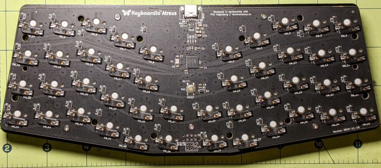
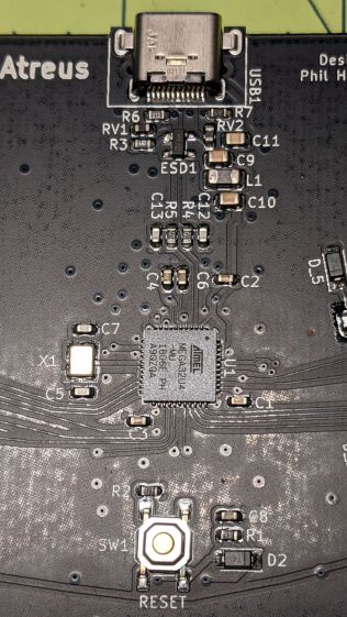
Removing a dozen screws lets you take it apart, revealing all the electronics on the underside of the PCB:
Atreus keyboard – PCB overview
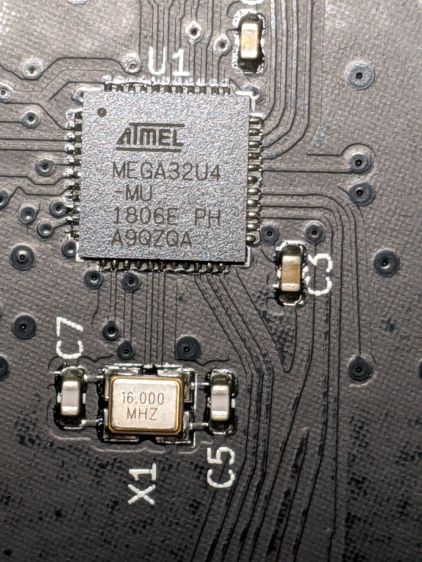
The central section holds most of the active ingredients:
Of interest is the JTAG header at the front center of the PCB:
Atreus keyboard – JTAG header
I have yet to delve into the code, but I think those signals aren’t involved with the key matrix and one might be available to drive an addressable RGB LED.
For future reference, they’re tucked into the lower left corner of the chip (the mauled format comes from the original PDF):
Atmel 32U4 – JTAG pins
The alternate functions:
SCK = PB1
MOSI = PB2
MISO = PB3
I don’t need exotic lighting, but indicating which key layer is active would be helpful.
Love the key feel, even though I still haven’t hit the B key more than 25% of the time.
No CUPS server setup can be considered complete without sending a print job to the wrong printer:
HPLJ1200 – CUPS Pinball Panic – detail
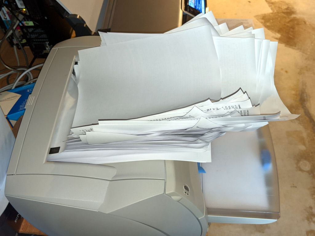
Which wouldn’t be quite so bad if the printer weren’t ever so much faster than I am:
HPLJ1200 – CUPS Pinball Panic – output pileup
It turns out an ordinary clothes iron can flatten those pages. Set it to “silk”, spread packing paper on the ironing board to intercept the toner, iron a few millimeters of pages at a time, and feed them back into the printer.
Back in the day, laser-specific printer paper came with a grain arranged so it wouldn’t curl when you fed it into the printer with the proper side up. Those days are gone; I’ve tried both ways and they both curl.
Protip: When CUPS thinks it’s done with the job and the Web interface shows nothing’s going on, it’s handed the job to the server’s printing subsystem, which continues spooling data to the printer. Choking off the bitstream requires one command-line invocation on the server connected to the printer:
cancel -a
A paper jam gives you enough time to figure all that out.
Tweaking a new Manjaro Linux 20.1 installation to share printers and allow remote administration, done while replacing an aging Optiplex desktop box that’s been running unattended for far too long.
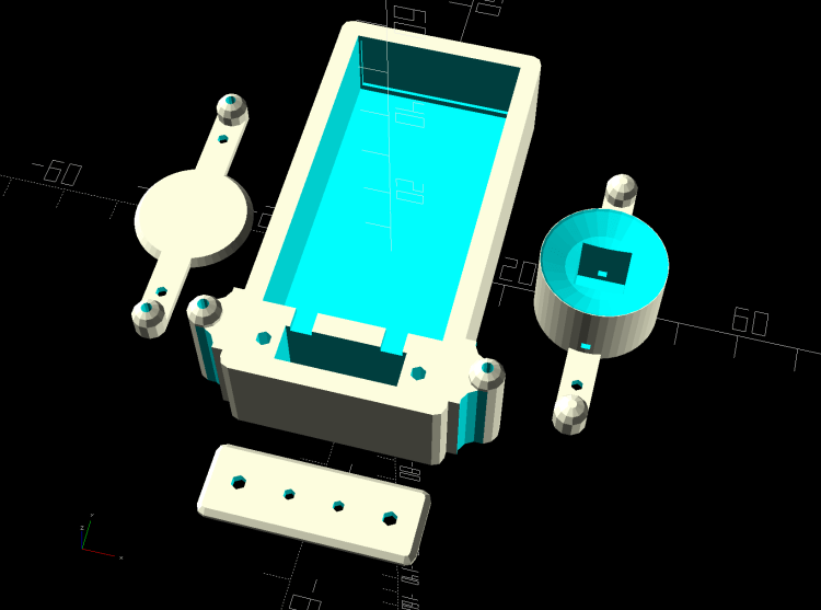
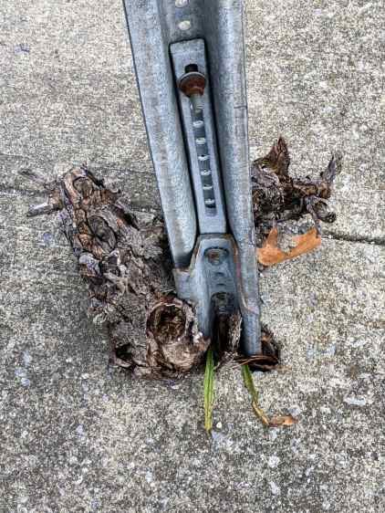
The stiffness of the bike helmet mirror mount suggested a similar clamp would have enough griptivity to immobilize the ball while cutting it in the lathe:
Helmet Mirror Mount – 10 mm ball
Building the clamp around the lathe’s three-jaw lathe chuck eliminates the need for screws / washers / inserts:
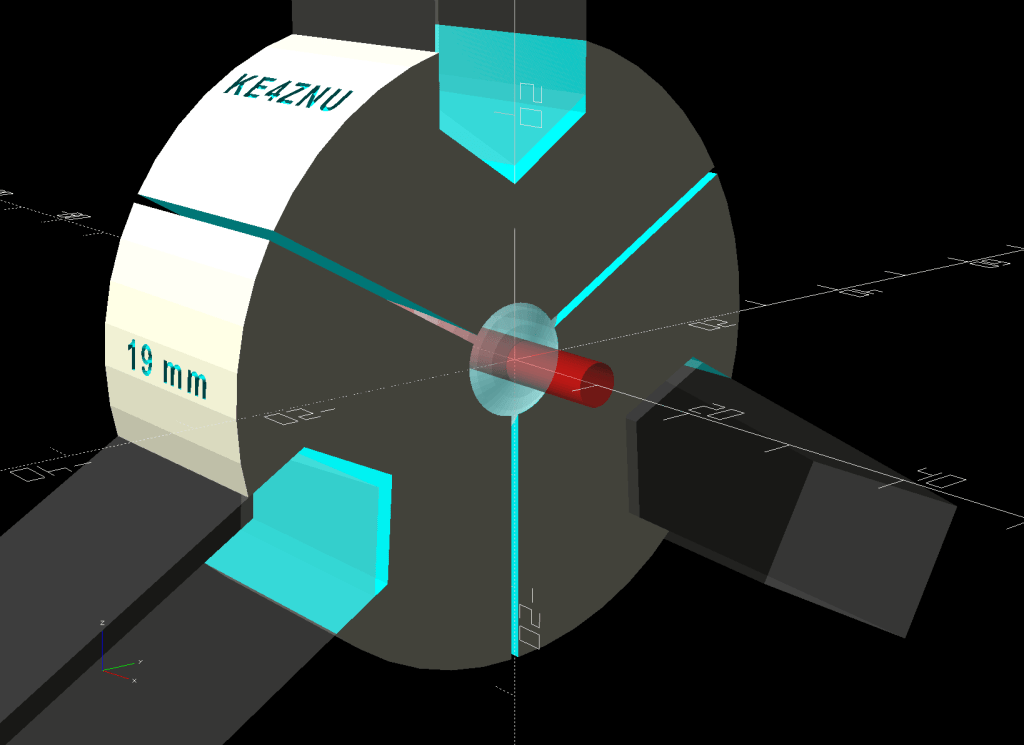
Lathe Ball Fixture – 19 mm – Show
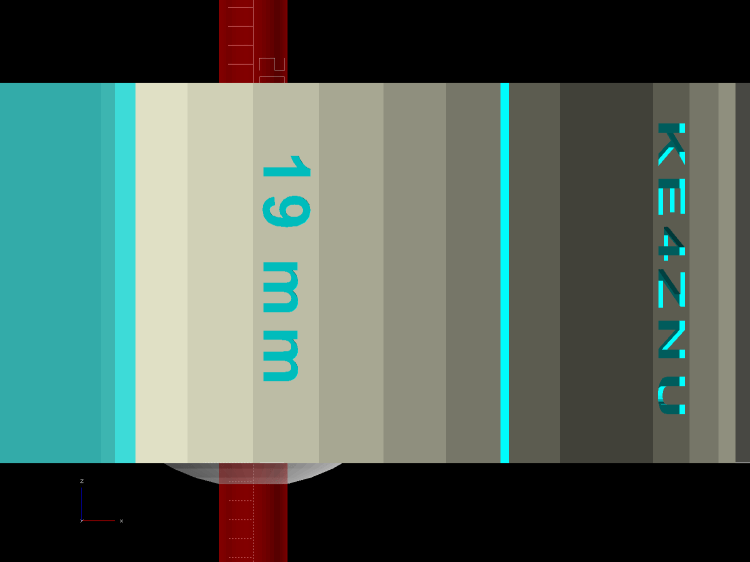
The Ah-ha! moment came when I realized the fixture can expose half of the ball’s diameter for drilling while clamping 87% of its diameter, because 0.5 = sin 30° and 0.87 = cos 30°:
Lathe Ball Fixture – 19 mm – Show – front orthogonal
That’s an orthogonal view showing 13% of the ball radius sticking out of the fixture; it’s 6% of the diameter.
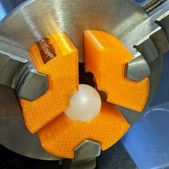
Which looks like this in real life:
Lathe Ball Fixture – 19 mm – sections with ball
The socket is offset toward the tailstock end of the clamp (on the right in the picture) to expose half its diameter flush with the surface perpendicular to the lathe axis. The other side necks down into a cylinder of the same diameter to clear the drill bit.
This works nicely until the ball diameter equals the chuck jaw’s 20 mm length, whereupon larger balls protrude into the chuck body’s spindle opening. Although I haven’t yet built one, the 25 mm balls in my Box o’ Bearings should fit, with exceedingly sissy cuts required for large holes.
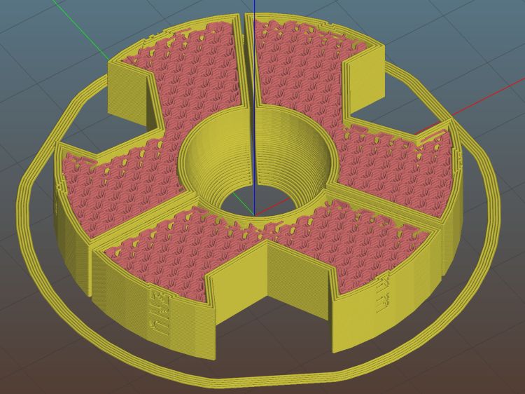
The fixture doesn’t require support material, because the axial holes eliminate the worst of the overhang. Putting the tailstock side flat on the platform gives it the best-looking surface:
Lathe Ball Fixture – 19 mm – Slic3r – equator
The kerf between the segments ensures the jaws can apply pressure to the ball, whereupon the usual crappy serrated 3D printed surface firmly grabs it.
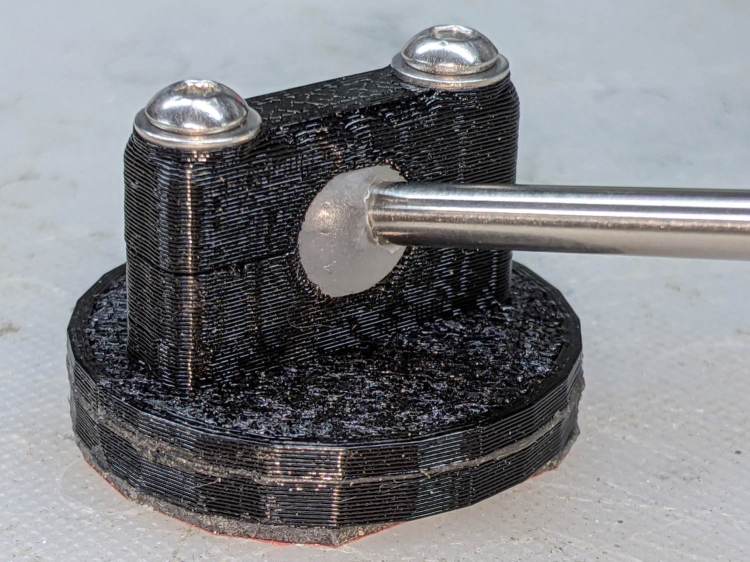
The fixture is a slip fit on the chuck jaws:
Lathe Ball Fixture – 19 mm – installed
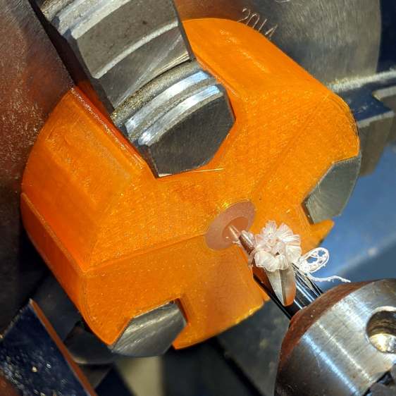
Tightening the jaws shoves them all the way into the fixture’s slots and clamps the ball:
Lathe Ball Fixture – 19 mm – center drill
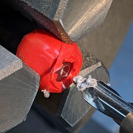
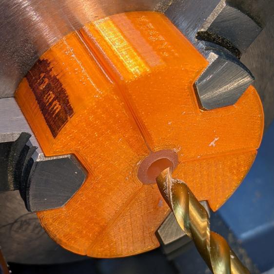
Overtightening the chuck will (probably) compress the ball around the drill, which will (best case) give you slightly oversize holes or (worst case) cause the ball to seize / melt around the drill bit, so sleaze up to the correct hole diameter maybe half a millimeter at a time:
Lathe Ball Fixture – 19 mm – 6 mm drill
That fixture exposes 9.5 mm = 19/2 of the ball. The drill makes a 6 mm hole to fit the telescoping shaft seen above.
Obviously, you must build a custom fixture for every ball diameter in your inventory, which is no big deal when you have a hands-off manufacturing process. Embossing the diameter into the fixture helps match them, although the scribbled Sharpie isn’t particularly elegant.
This file contains hidden or bidirectional Unicode text that may be interpreted or compiled differently than what appears below. To review, open the file in an editor that reveals hidden Unicode characters.
Learn more about bidirectional Unicode characters