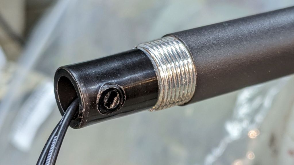
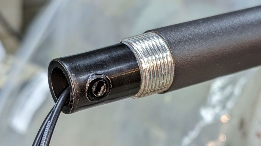
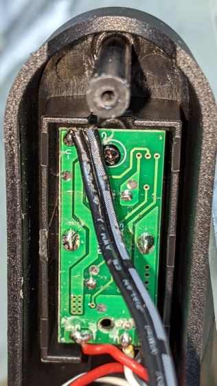
A few months of inactivity left the CNC-3018XL table parked in its homed position where the gentle-but-inexorable pressure of the switch lever displaced the foam holding the plastic actuator tab on the X-axis bearing enough that it would no longer operate reliably:
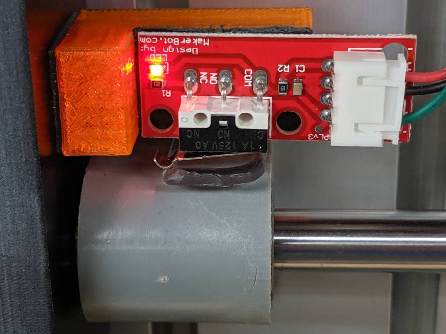
Putting foam tape in a highly leveraged position produces the same poor results as in finance.
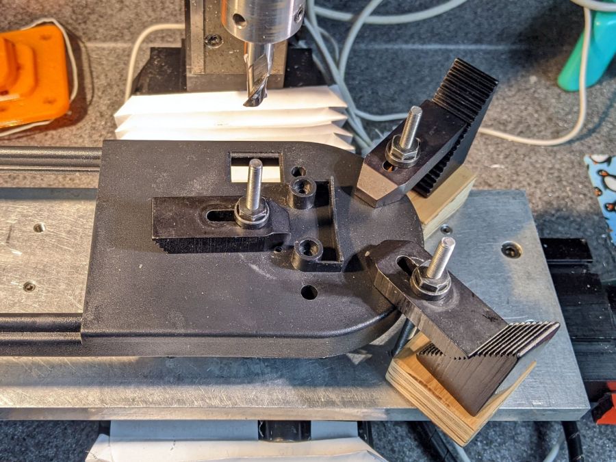
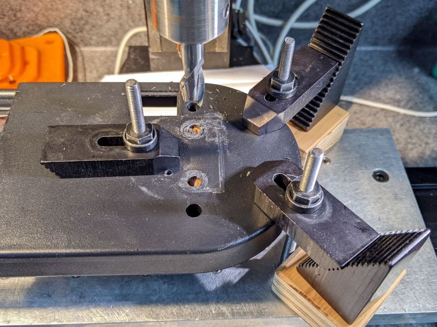
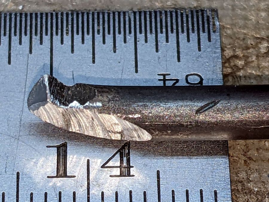
The fix requires reorienting the switch so a solid block on the bearing can push directly on the actuator lever:

The block must curve around the bearing to give the tape enough surface area for a good grip:

The solid model for the new X-axis mount looks about like you’d expect:

I increased the home switch pulloff to 2 mm, although it’s not clear that will make any difference in the current orientation.
The OpenSCAD source code as a GitHub Gist:
| // 3018-Pro Mount for Makerbot Endstop PCB | |
| // Ed Nisley KE4ZNU – 2019-07 (using OEM machine axes) | |
| // 2022-02-02 rotate X block (after renaming axes to match new layout) | |
| /* [Build Options] */ | |
| Layout = "Show"; // [Build, Show] | |
| /* [Hidden] */ | |
| ThreadThick = 0.25; // [0.20, 0.25] | |
| ThreadWidth = 0.40; // [0.40] | |
| function IntegerMultiple(Size,Unit) = Unit * ceil(Size / Unit); | |
| Protrusion = 0.01; // [0.01, 0.1] | |
| HoleWindage = 0.2; | |
| ID = 0; | |
| OD = 1; | |
| LENGTH = 2; | |
| //- Shapes | |
| // Basic PCB with hole for switch pins | |
| // origin at switch actuator corner, as seen looking at component side | |
| SwitchClear = [15.0,5.0,2.0]; // clearance around switch pins | |
| SwitchOffset = [12.5,9.0,0.0]; // center of switch pins from actuator corner | |
| PCB = [26.0,16.4,2*SwitchClear.z]; // switch PCB beyond connector, pin height | |
| //XBlock = [PCB.x + 10.0,PCB.y,20.0]; | |
| XBlock = [PCB.x,PCB.y,10.0]; | |
| XBearing = [10.0,26.5,28.5]; | |
| XPin = [10.0,20.0,10.0]; | |
| module XMount() { | |
| if (false) // side-push switch tended to slip | |
| difference() { | |
| translate([-10.0,0,0]) | |
| cube(XBlock,center=false); | |
| translate([0,-Protrusion,10.0]) | |
| cube(XBlock + [0,2*Protrusion,0],center=false); | |
| translate(SwitchOffset + [0,0,10.0 – SwitchClear.z/2]) | |
| cube(SwitchClear + [0,0,Protrusion],center=true); | |
| } | |
| else { | |
| difference() { | |
| cube(XBlock,center=false); | |
| translate(SwitchOffset + [0,0,XBlock.z – SwitchClear.z/2]) | |
| cube(SwitchClear + [0,0,Protrusion],center=true); | |
| } | |
| translate([1.25*XBlock.x,0,0]) | |
| difference() { | |
| cube(XPin + [0,0,XBearing[OD]/4],center=false); | |
| translate([-Protrusion,XPin.y/2,XPin.z + XBearing[OD]/2]) | |
| rotate([0,90,0]) | |
| cylinder(d=XBearing[OD],h=XPin.x + 2*Protrusion,center=false); | |
| translate([-Protrusion,-XPin.y/2,XPin.z]) | |
| cube(XPin + [2*Protrusion,0,0],center=false); | |
| } | |
| } | |
| } | |
| YBlock = [PCB.x,PCB.y,5.0]; | |
| module YMount() { | |
| difference() { | |
| cube(YBlock,center=false); | |
| translate(SwitchOffset + [0,0,YBlock.z – SwitchClear.z/2]) | |
| cube(SwitchClear + [0,0,Protrusion],center=true); | |
| } | |
| } | |
| ZBlock = [PCB.x,PCB.y,6.0]; | |
| ZPin = [20.0,10.0,5.5]; | |
| module ZMount() { | |
| difference() { | |
| cube(ZBlock,center=false); | |
| translate(SwitchOffset + [0,0,ZBlock.z – SwitchClear.z/2]) | |
| cube(SwitchClear + [0,0,Protrusion],center=true); | |
| } | |
| translate([1.25*ZBlock.x,0,0]) | |
| difference() { | |
| cube(ZPin,center=false); | |
| translate([ZPin.x/2,-Protrusion,4.0]) | |
| cube(ZPin + [0,2*Protrusion,0],center=false); | |
| } | |
| } | |
| //- Build things | |
| if (Layout == "Show") { | |
| translate([0,XBlock.y,0]) | |
| YMount(); | |
| translate([0,-XBlock.y/2]) | |
| XMount(); | |
| translate([0,-(ZBlock.y + XBlock.y)]) | |
| ZMount(); | |
| } |