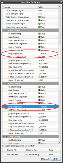
After tweaking the OMTech laser’s axis scale calibration, it seemed like a good idea to see whether the axes run perpendicular to each other:
A carpenter’s framing square isn’t the most precise instrument, but the pair in my collection agree on their right-angularity to within my ability to measure the difference.
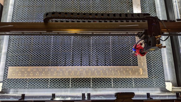
Aligning the short arm with the Y axis showed the X axis was off by 1.2 mm in 21 inches = 530 mm, an angle of 0.13°, which is just about as good as it’s ever going to be.
The honeycomb frame is definitely not a precisely aligned unit, but the front edge is parallel to the X axis within an astonishing 0.03°, measured along the rear edge of the long arm pushed against the front of the frame. The aluminum frame has a distinct outward bow in the middle averaged out by the long arm.
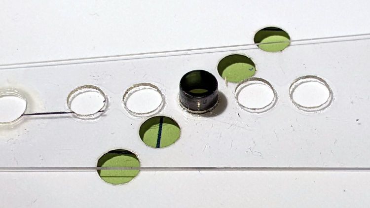
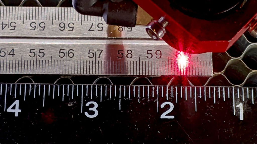
Unfortunately, the honeycomb frame on the right side is nowhere near that nice. While I had the long scale aligned with the X axis travel, I sleazed a smaller square up against it:
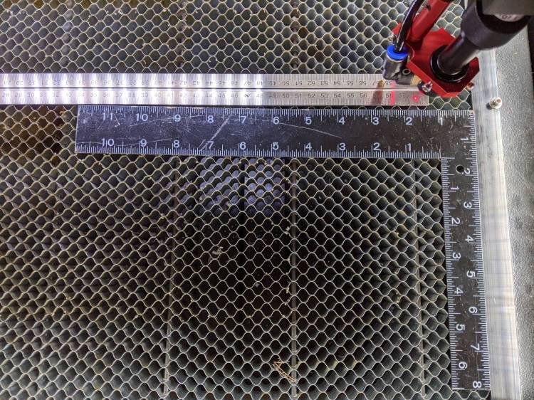
It’s as bad as it looks:

The scale departs from the black square’s arm by 4 mm over 260 mm, for a 0.88° misalignment.
I think the honeycomb frame is, at best, a parallelogram (and likely a trapezoid), and each side is also bowed by a few millimeters along its length, so any misalignment will depend on where you stand and which way you look.
In all fairness, it was never intended as an alignment fixture and nobody really cares about angular misalignment as long as the puppy portrait comes out pretty much in the middle of the coaster.

Yes, yes I am.
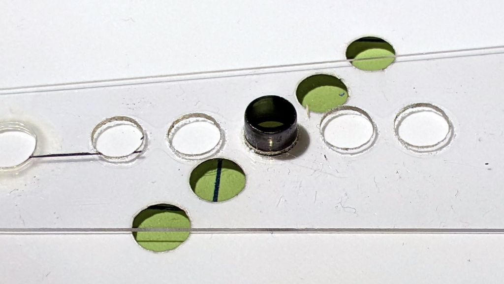
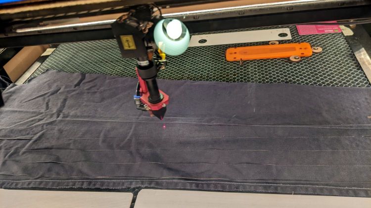
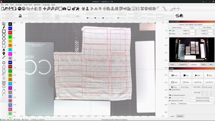
It’s easy enough to make an alignment fixture:

The cut along the left edge is, by definition, parallel to the Y axis, so the left edge of the larger slice serves to align flat things to be cut and hold them in place:
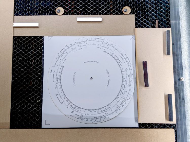
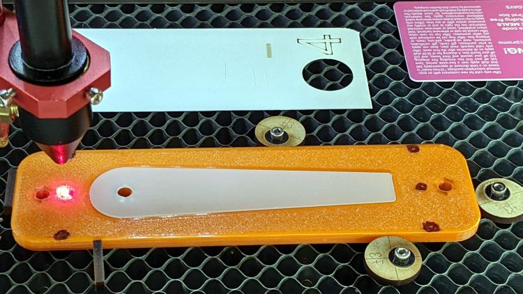
The upper sheet (a simple chipboard rectangle) sits perpendicular (set with the short square) to the edge, held to the honeycomb with magnets, and kept in alignment with two adjustable stops snugged against it. A few smaller magnets can hold the sheet flat against the honeycomb as needed.
The sliver cut off the MDF is 7.85 mm at the top and 9.70 mm at the bottom, for an angle of 0.53° over its 210 mm length, a bit less than the angle measured above. It now lives in the tooling pile against future need.