Mary’s PT requires a Shoulder Pulley, so I got one that seemed better constructed than the cheapest Amazon crap. In particular, this view suggested the pulley ran on a bearing:

Which turned out to be the case, but, also as expected, the whole thing required a bit of finishing before being put in service.
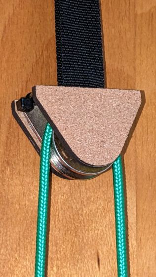
It’s intended to hang from a strap trapped between an interior door and its frame. The strap was intended to attach to the block (a.k.a. “Thickened base”) through a breathtakingly awkward pair of low-end carabiners:

Which I immediately replaced with a simple, silent, sufficiently strong black nylon cable tie:

Rather than let the metal block clunk against the door, it now sports a pair of cork-surfaced bumper plates:
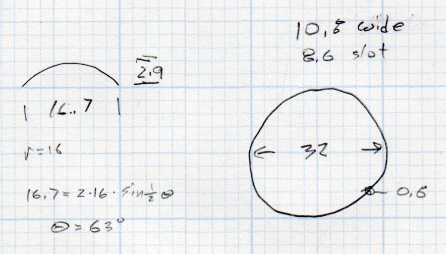
A doodle of the block dimensions:
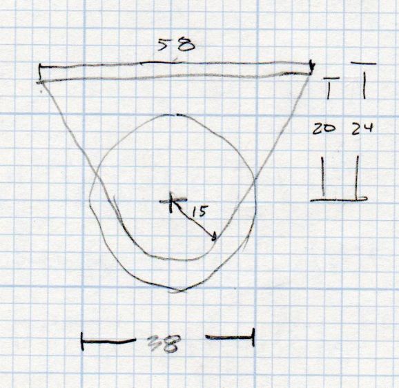
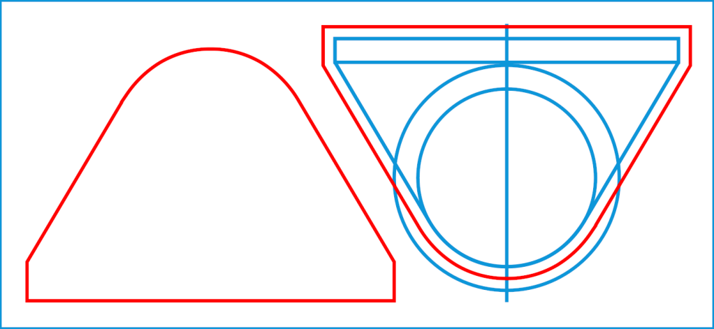
Which turned into a simple LightBurn layout:

The blue construction lines represent the actual block & pulley, with the red cut lines offset 2 mm to the outside to ensure the metal stays within the bumpers. It’s possible to pick the block up and whack the pulley against the door, so don’t do that.
Cut out two pieces of 3 mm MDF, two pieces from a cork coaster (covered with blue tape and cut with the paper backing up), peel-n-stick the cork to the MDF, put double-sided foam tape on the block, peel-n-stick the bumpers, then hang on the attic door.
Now it works the way it should!
The LightBurn SVG layout as a GitHub Gist:


