Ed Nisley's Blog: Shop notes, electronics, firmware, machinery, 3D printing, laser cuttery, and curiosities. Contents: 100% human thinking, 0% AI slop.
Tag: Improvements
Making the world a better place, one piece at a time
As expected, the internal battery does not last for our usual hour-long rides, so the cameras now operate in “car mode”: recording starts when we plug in the USB battery pack and stops shortly after unplugging.
I started with the waterproof case on my bike:
Tour Easy – SJCAM C100 mount – installed
Which (obviously) does not allow for an external battery, so they’re now in the “frame” mount. The hatch covering the MicroSD card and USB Micro-B connector (and a Reset button!) is on the bottom of the camera, but (fortunately) the whole affair mounts up-side-down and the settings include an image flip mode.
The ergonomics / user interface of this whole setup is terrible:
The camera’s flexible hatch is recessed inside the frame far enough that it cannot be opened without using a small & sharp screwdriver
The USB jack is slightly off-center, so lining the plug up with the camera body doesn’t align it with the jack
The MicroSD card is in a push-to-release socket, but its raised ridge faces the hatch flap and cannot be reached by a fingernail. I added a small tab that helps, but it’s difficult to grasp.
Extracting the video files from the camera through the app is an exercise in frustration. Having already figured out how to do this for the other cameras in the fleet, it’s easier to fumble with the MicroSD card.
I devoutly hope we never really need any of the videos.
The trail camera uses two parallel banks of four series AA cells to get enough oomph for its IR floodlight. I’m not convinced using bucked lithium AA cells in that configuration is a Good Idea, but it’s worth investigating.
These are labeled HW, rather than Fuvaly, because it seems one cannot swim twice in the same river:
HW bucked Li AA cells
In any event, they come close to their claimed 2.8 W·hr capacity:
HW bucked Li AA – 2023-05
The lower pair of traces (red & black) are single cells at 2.7-ish W·hr, the blue trace is a pair at 5.4 W·hr, and the green trace is a quartet at 9.8 W·hr. Surprisingly close, given some previous results in this field.
Recharging the cells after those tests shows they all take 3 hours ± a few minutes to soak up 730 mA·hr ± a few mA·hr, so they’re decently matched.
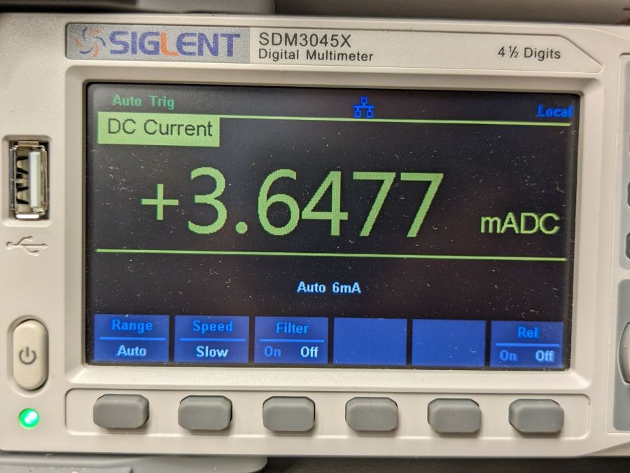
Measuring the terminal voltage with a 10 mA load after that charge lets me match a pair of quartets to 1 mV, which is obviously absurd:
HW bucked Li cells – initial charge 2023-05-05
The numbers in the upper left corner show the initial charge of four cells at a time required the same time within a minute and the same energy within 4%.
Sticking them in the trail camera must await using up the current set of alkaline AA cells.
Bonus: a lithium fire in a trail camera won’t burn down the house.
After all, pictures like this are definitely worth the hassle:
It’s more properly called a “chain guide” and is basically a shifter cage minus the mechanism:
Chain Catcher – side view
Because the Tour Easy frame has a 25 mm tube where the guide’s clamp expects a minimum 31.8 mm tube, a 3D printed adapter fills the gap:
Chain Catcher adapter ring – solid model
The hole is off-center because it seemed like a good idea, although it’s not strictly necessary. The flange helps align the pieces while tightening the clamp screw.
The guide cage clears the chain on all sides while up on the work stand, but there’s nothing like getting out on the road to find out why something doesn’t work as you expect.
This file contains hidden or bidirectional Unicode text that may be interpreted or compiled differently than what appears below. To review, open the file in an editor that reveals hidden Unicode characters.
Learn more about bidirectional Unicode characters
When the chain falls off the top of the chainring toward the motor, the part remaining engaged with the chainring will inevitably drag the rest into the gap between the motor and the chainring spider, whereupon it will jam firmly in place and be almost impossible to extract. Preventing this means filling the gap, which required several iterations:
Bafang motor gap filler – prototypes
The Bafang motor has a cover held in place by seven M3 flat-head screws, shown here below a test filler using pan head screws:
Bafang motor gap filler – installed
Contrary to what you might think, the five screws that obviously sit on five points of a hexagon do not in fact sit 60° apart. How you find this out is by making the obvious layout, including the two screws bracketing the pinion gear in the lower right, then applying windage:
Bafang motor housing gap filler – hole adjustments
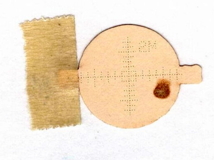
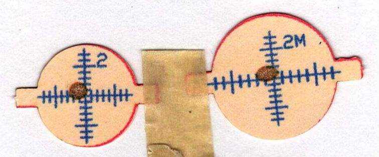
That’s one of the paper templates seen above, with laser-cut holes 60° apart and ugly holes punched at the actual screw locations. Then you scan and overlay that image with the LightBurn layout and twiddle the hole locations to make the answer come out right:
Bafang motor housing gap filler – hole adjustments – LB overlay
With that in hand, I cut a 1 mm acrylic shape to measure the clearance between the motor + filler and the chainring spider, with pan-head screws replacing the original flat-head screws:
Bafang motor gap filler – top view
That’s a single piece of 2.5 mm acrylic I used after discovering a pair of the 1 mm acrylic shapes fit with space to spare: hooray for rapid prototyping.
A test chain drop suggested it might suffice:
Bafang motor gap filler – test
If I were so inclined, 3 mm acrylic with countersunk holes and slightly longer flat-head screws would probably work, but I’ll use this until it fails to prevent a chain snag.
The careful observer will have noted the stress crack extending radially inward from the upper-right screw, which I am carefully avoiding doing anything about, pending the aforementioned failure.
Having acquired some thick-wall (1 inch OD, ¾ inch ID) aluminum tube, making the LED heatsink and lens holder for a running light generates a lotless scrap. A new doodle gives the dimensions in a rather Picasso-ish layout:
Running Light – dimension doodles
The back end of the tube gets turned down to 23 mm OD and cleaned up to 19 mm ID, then scored to give the epoxy something to grip:
Front Running Light – Heatsink shell scoring
The front end gets bored to 22.5 mm for the lens holder and has its OD cleaned up to 25 mm:
Front Running Light – finished shell
Clean up the end of a ¾ inch rod to 19 mm OD, knurl it a little to increase the OD ever so slightly and improve its griptivity, slice off a bit more than 10 mm, butter it up with JB Weld epoxy, and shove it into the shell with its front end aligned and its back end sticking out:
Front Running Light – epoxied plug in shell – rear
Face off the back end and the front end looks fine as assembled:
Front Running Light – epoxied plug in shell – front
Grab it in the Sherline mill’s three jaw chuck to:
Drill & tap the M3 central hole for the stud holding the circuit plate to the back end
Drill 1.6 mm blind holes for the circuit plate pins
Drill 2 mm through holes for the LED wires, 60° apart
Which looks like this from the front:
Front Running Light – drilled heatsink – front
And like this with the circuit plate screwed & glued to the rear:
Front Running Light – circuit plate mounted
Clean up the OD of some ¾ inch PVC pipe to 25 mm, bore it out to 23 mm.
While the Sherline is set up, drill a pair of 2 mm holes in the lens holder for the wires, aligned so they’ll match the heatsink holes.
Because we live in the future, laser-cut the rear cap from some edge-lit acrylic with a black inner disk:
Front Running Light – PVC tube – end cap
Cutting that cap with the notch included is now trivially easy, compared to the previous machining.
While I was thinking about something else, I added a back shield to our kitchen scale:
SmartHeart 19-106 Scale – button shield
A pogo pin connected to the circuit common contacts the copper foil when the bottom cover is screwed down:
SmartHeart 19-106 Scale – shield pogo pin – detal
The shield prevents the buttons from responding to fingers on the bottom of the scale, so it no longer wakes up when I extract it from the under-cabinet shelf, and concentrates its attention on the buttons, so it no longer seems quite so willing to lock up due to mysterious influences.
With an absurd amount of rebuilding, this scale is becoming not a complete waste of free money.
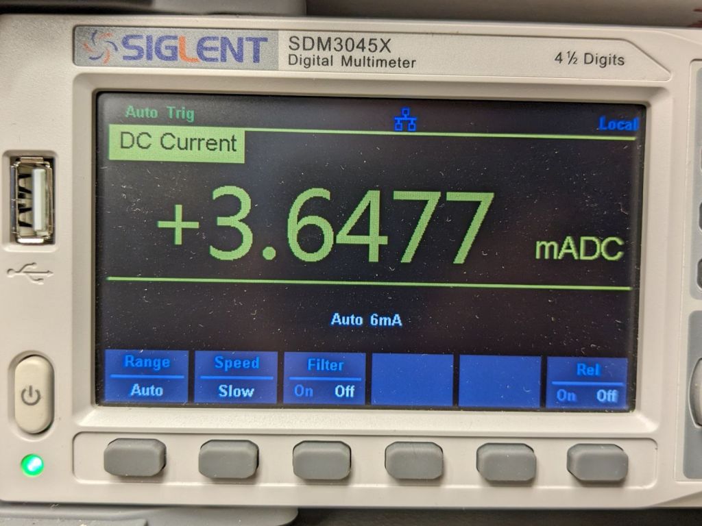
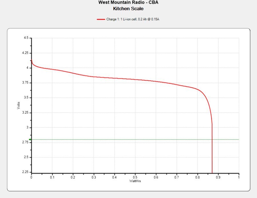
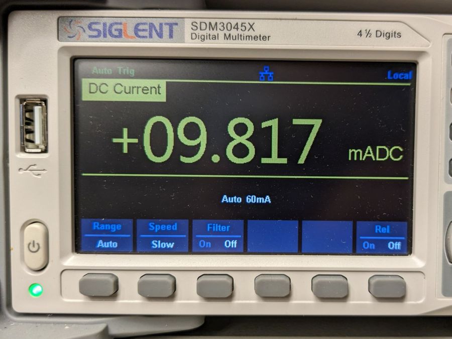
The batteries soaked up 240 mA·hr of charge, which means the scale drew about 10 mA/day over the last three weeks. Given that the scale’s original 2032 lithium cells have a total capacity around 220 ma·hr for currents in the microamp range, expecting them to supply a current around 10 mA is was absurd.
Note that it’s possible to see the inlet, but not do much with it. I think the bottom plate could be pried off those squishy rubber pillars supporting / isolating the pump, but I didn’t see any need to do so.
The doodle I made at the time gives the dimensions:
OMTech 60 W Laser Air Assist – pump inlet fitting measurements
Back then, I thought of 3D printing the fitting, but the fact that the parts had to be 1.5 mm thick suggested laser cutting the parts from acrylic sheet:
Laser cutter air pump – keyed fitting A – parts
The three top disks come from a 3M LSE adhesive sheet and hold the three layers together, with one spare because I know better than to cut exactly as many as I think I’ll need:
Laser cutter air pump – keyed fitting – assembled
The alert reader will note the middle layer in that picture isn’t a simple round disk. After putting the first version together, I realized the keyed bottom layer could continue turning until it fell out, so I added stops to the middle disk:
Laser cutter air pump – keyed fitting B – parts
Those stops came from the bottom layer layout by welding together three copies of the key opening:
Laser Cutter Air Assist Pump Fitting – LB design layout
Space three of those shapes around the ring, subtract them from the outer disk (the same size as the keyed layer), weld them to the middle disk (the same size as the previous middle), and the stops appear as if by magic. Gotta love this geometry stuff.
The same design produced matching adhesive disks that I applied with tweezers, but if you were doing it in production you’d definitely want to apply a sheet of adhesive to a sheet of acrylic and cut them in the same operation.
Soften the slightly curved PVC tubing with a heat gun, persuade it to become straight, jam a drill bit inside and grab it in the lathe chuck to keep the fitting perpendicular, glob hot-melt glue around the tubing to hold it in place, and let it cool:
Laser cutter air pump – fitting hose glue
Hot melt glue doesn’t adhere well to acrylic, so cut & apply a disk of LSE adhesive between them, because it sticks like … glue … to both substances.
Mark and step-drill a hole in the bottom of the laser cabinet, install the fitting on the pump, line things up, and it’s ready to screw down:
Laser cutter air pump – first trial fitting
Whereupon I discovered the four silicone rubber feet I added to support the pump base plate and keep it from vibrating against the cabinet let the flexy rubber posts supporting the pump extend too far, thus causing the whole pump to rest on the glue around the fitting.
Well, I can fix that and, while I’m at it, a snippet of fibrous stuff will keep the tube from rattling around:
Laser cutter air pump – bottom view – assembled
The four clear disks are 3 mm acrylic stuck to the rubbery feet with more LSE adhesive, with rings around the top to keep everything aligned. It may be possible to line up all four of those things while lowering the pump in place, but not for me.
With all that once again ready to screw down, the blue tube and its fuzzy felt bumper fell right off, taking the pump’s air inlet connector along. Much to my surprise, the pump draws air through a simple 6 mm hole in its bottom plate:
Laser cutter air pump – without fitting socket
Now, the reason I went through all these gyrations was because I had examined that connector, decided it was an integral part of the pump, and there was no way for me to get it off without tearing the pump apart or applying brute force.
Apparently, all the twisting & turning I did while getting the fittings assembled worked the connector’s unthreaded stem loose in its hole, ready to come out with the slightest pull.
Verily: Hell hath no fury like that of an unjustified assumption.
So I cut out a simple disk of 4.5 mm acrylic, hot-melt blobbed a 6 mm ID silicone tube into it, stuck it onto the pump with a (punch-cut!) disk of 3M double-sided foam tape, and declared victory:
Laser cutter air pump – simple disk fitting
Fortunately, the step drill I used on the cabinet left a 9.5 mm hole easily passing the silicone tube’s 9 mm OD, so it all fit together just like I knew what I was doing.
The silicone tubing has a much larger ID than the original plastic fitting, but the assist air flow remains around 10 l/min. That’s down from the 14 l/m when I installed the flowmeter and 12 l/min with the dual-path assist air control plumbing, but didn’t change with all this fiddling, so the real restriction is in all the blue tubing and myriad fittings on the way to the nozzle.
On the upside, I now know a bit more about small-scale laser cutting and am well-satisfied with the results.