LightBurn includes a Slot & Tab Resizer tool that automagically finds and resizes joints to adapt a design for whatever material thickness you might be using. To judge from the LightBurn forum threads, it doesn’t deal well with random designs fetched from the Interwebs, which suggests those designs were either never intended for laser cuttery or just badly laid out.
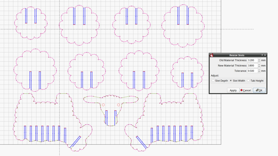
So I fetched a sheep from a typical sketchy source and attempted to resize its slots:
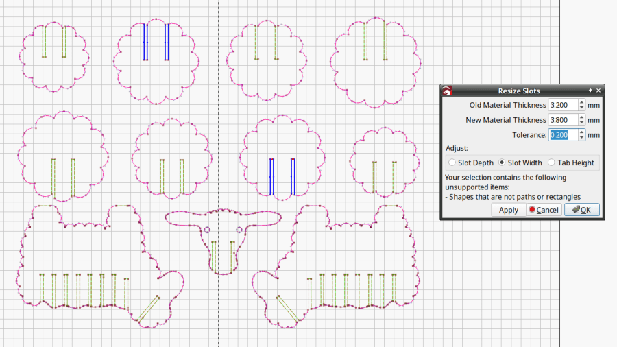
The tool looks for rectangular shapes within the Tolerance of the Old Material Thickness width, then marks their narrow ends with red highlights and their length with blue. Obviously, not all of the slots we humans see count as slots.
A closer look at one of the body shapes with a slightly larger Tolerance shows some of the problems:

Using the Node Editor tool reveals two stray nodes near the bottom of the second slot from the left:

Zooming in and blowing out the contrast:

Manually deleting those nodes doesn’t solve the problem, because two more errant nodes lurk at the top of the slot:

You probably didn’t notice those at first glance, either. Those nodes may be very close together, but they still confuse the issue.
Rather than tracking down and deleting / adjusting those nodes one by one, you can apply the Optimize Shapes tool to squash the superfluous nodes into straight lines:
Don’t smooth the shapes or fit them to arcs at this point, because both of those operations will round off the corners.
That may still leave a few nodes requiring manual intervention, as on the face shape:

But at least the problem becomes tractable:

As the Bard put it, all’s well that ends well.