Ed Nisley's Blog: Shop notes, electronics, firmware, machinery, 3D printing, laser cuttery, and curiosities. Contents: 100% human thinking, 0% AI slop.
Tag: Improvements
Making the world a better place, one piece at a time
An entry from The New Garden Encylopedia, copyright 1936 through 1946, gives recommendations for using arsenical poisons in your garden:
Arsenical poisons
My father always said anybody who talks fondly of The Good Old Days wasn’t alive back then. He was and thought things had definitely improved since then.
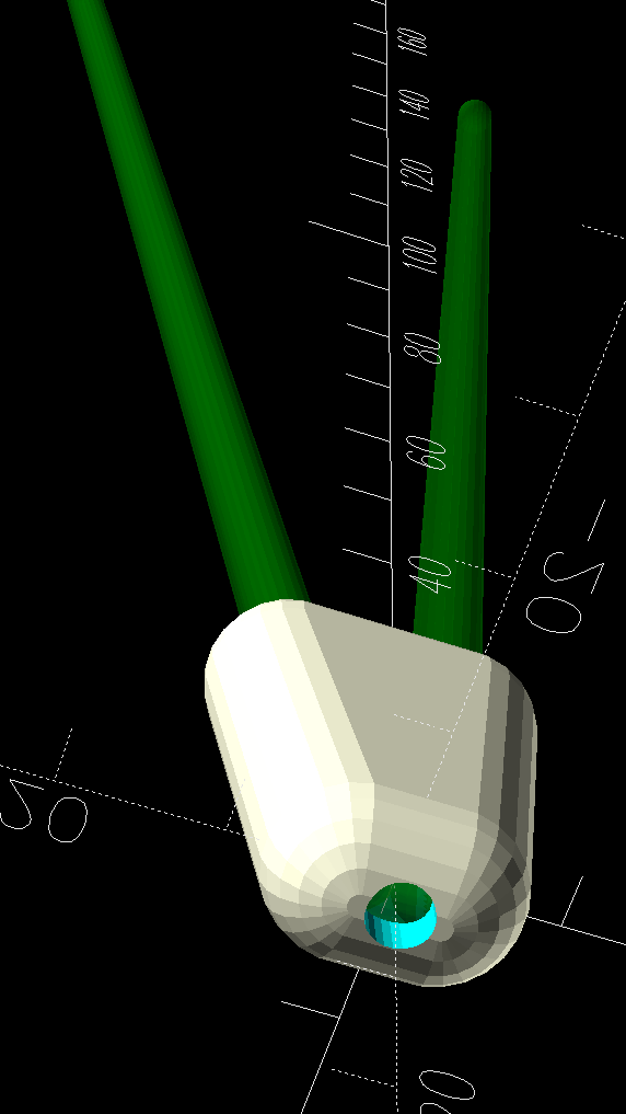
A pair of plant stands from a friend’s collection ended up in Mary’s care and cried out for feet to keep their welded steel wire legs from scratching the floor:
Wire plant stand feet – indoor stand
Admittedly, it’s not the prettiest stand you can imagine, but the sentimental value outweighs all other considerations.
The feet are shrink-wrapped around the legs with enough curviness to look good:
Wire plant stand feet – show side view
With a drain hole in the bottom to prevent water from rusting the wires any more than they already are:
Wire plant stand feet – show bottom view
I briefly considered a flat bottom at the proper angle to sit on the floor, but came to my senses; it would never sit at the proper angle.
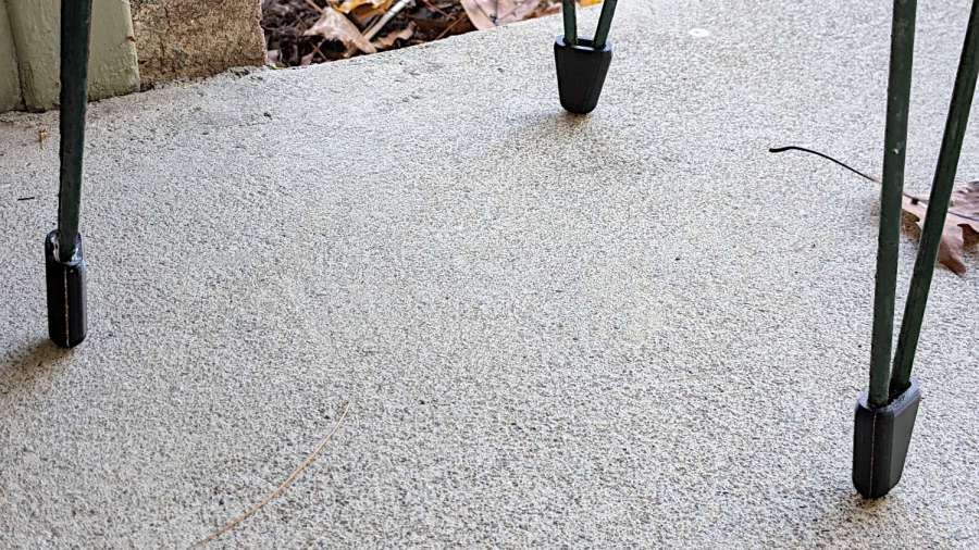
The end results snapped into place:
Wire plant stand feet – indoor detail
Of course the other stand, at first glance identical to the one above, has a different wire size and slightly different geometry, which I only discovered after printing another trio of feet. Changing the appropriate constants in the OpenSCAD program and waiting an hour produced a better outcome:
Wire plant stand feet – outdoor stand
Living in the future is good, all things considered.
This file contains hidden or bidirectional Unicode text that may be interpreted or compiled differently than what appears below. To review, open the file in an editor that reveals hidden Unicode characters.
Learn more about bidirectional Unicode characters
That’s the compression spring inside the curtain rod over the kitchen sink, intended to push the ends against the cabinets on either side. The screw slides along the outer rod and when tightened, backstops the spring against the inner rod.
The end of the spring is apparently intended to twist and jam inside the inner half of the rod, but that seemed so … unesthetic.
Being in the midst of setting up a Windows 11 box for the laser cutter, I used it as an excuse to fiddle with the RDP configuration to get LightBurn running in full screen mode on the monitor atop my desk; more about all that later.
The little pusher block is a hull around a pair of circles the same diameter as the smaller dimension of the inner rod, spaced apart enough to match its width, then laser-cut from a scrap of 1/4 inch acrylic:
Curtain rod pusher block – overview
Which assembles as you’d expect:
Curtain rod pusher block – installed
The spring seems much happier pushing against the block, doesn’t it?
Admittedly, this was completely unnecessary, but if you think of it as a side effect of the Win 11 thing, it makes at least a little sense.
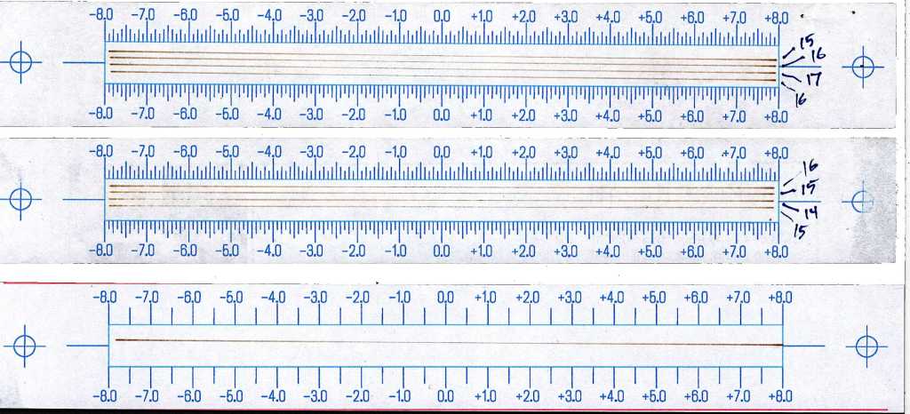
A few ramp tests with various Focus Distance + Home Offset settings as noted:
Ramp Test Targets – 14-17 mm
The bottom test was at 15 mm, which (contrary to previous estimates) seems to center the narrow band round 0.0 mm. Given the depth of field, a millimeter one way or the other likely doesn’t matter, particularly given the mmm lack of flatness in many materials.
The controller settings making it happen:
KT332N Autofocus settings
What they mean:
Home Offset = distance to retract after the autofocus “pen” = switch activates so the tip of the pen clears the material
Focus Distance = distance beyond Home Offset to put the focal point at the surface of the material (or wherever you want)
Enable Homing = makes autofocus work at the push of a button
Homing Speed = how fast the platform moves while focusing
Getting the focus right really makes the laser cut like it should!
Centering the autofocus “pen” = switch on the peg in the back puts the beam dead-center in the fixture, with the notches as comfort marks. The top of the peg is flush with the center notch, so the machine should be properly focused at that level after a focus operation.
Obviously, your laser has a different pen location, as will this one the next time I fiddle with anything around the nozzle.
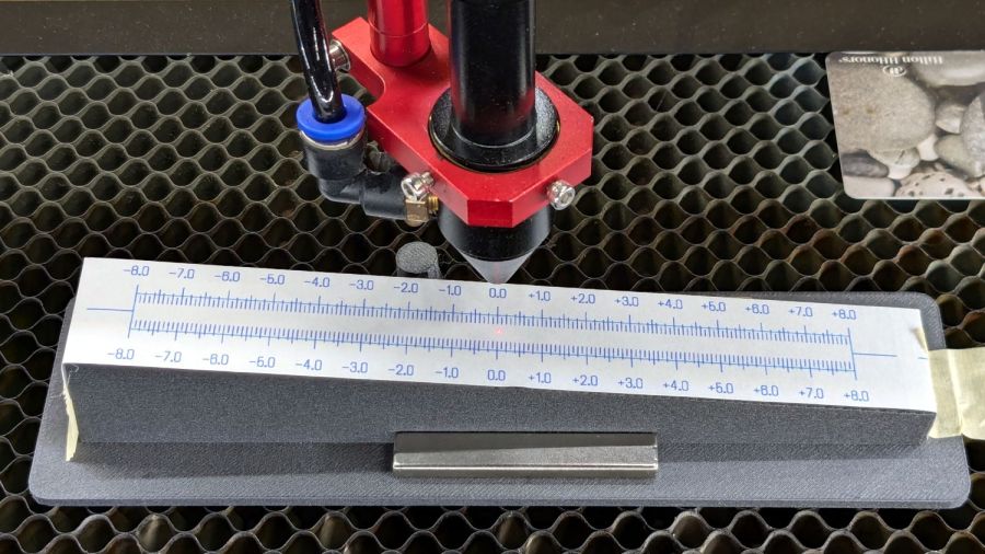
The general idea is to tape a target to the ramp, with some attention to flattening the paper (tape the edges in critical spots as needed) & putting its zero at the center marks, align the fixture to the laser path along the X axis & secure it with a few magnets, then burn a single line at low power along the length of the scale:
Ramp Test Fixture – laser line
The mark will be thinnest in the region with the best focus, which should be centered around the 0.0 mark in the middle. In that photo, the thinnest section runs from about -2.0 to +1.0, although (at least for me) it does take some squinting to be sure.
The ramp has a 1:10 = 5.71° slope to spread 1 mm of vertical focus across 10 mm of horizontal distance. If you’re being finicky, you should rescale the targets to correct the 0.5% cosine error, but IMO it’s irrelevant for this purpose.
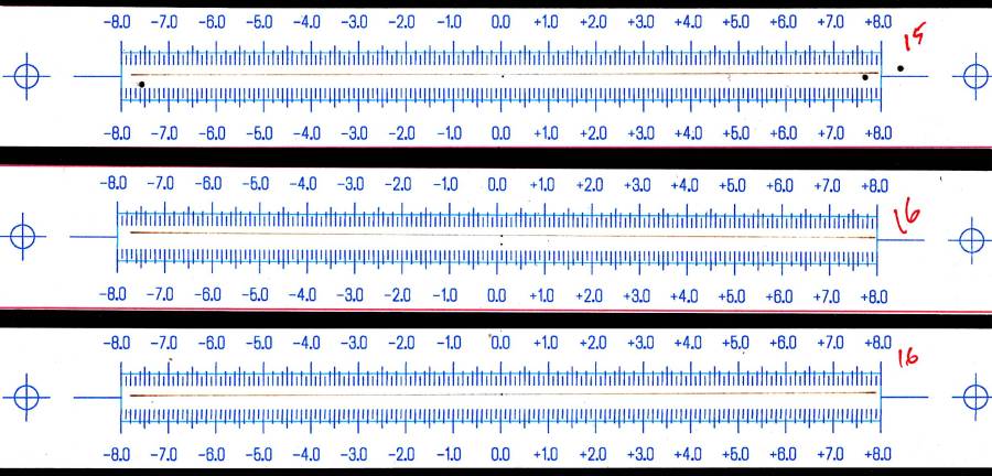
A few more tests varying the focus distance by a millimeter:
Ramp Test Targets – 15 16 mm
AFAICT, setting the controller’s Focus Distance to 16 mm is about right. That puts the focal point 18 mm below the nozzle, as shown in the earlier post, and is pretty much what I’ve been using all along.
The OpenSCAD code as a GitHub Gist, along with a simplified target layout in SVG format:
This file contains hidden or bidirectional Unicode text that may be interpreted or compiled differently than what appears below. To review, open the file in an editor that reveals hidden Unicode characters.
Learn more about bidirectional Unicode characters


