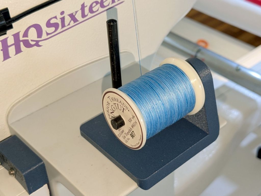
Mary’s practice quilts on the HQ Sixteen suggest locking the machine’s wheels will simplify sewing a line parallel to the long edge of a quilt parallel to the table, but contemporary “Channel Locks” fit newer machines with larger wheels than on this one.
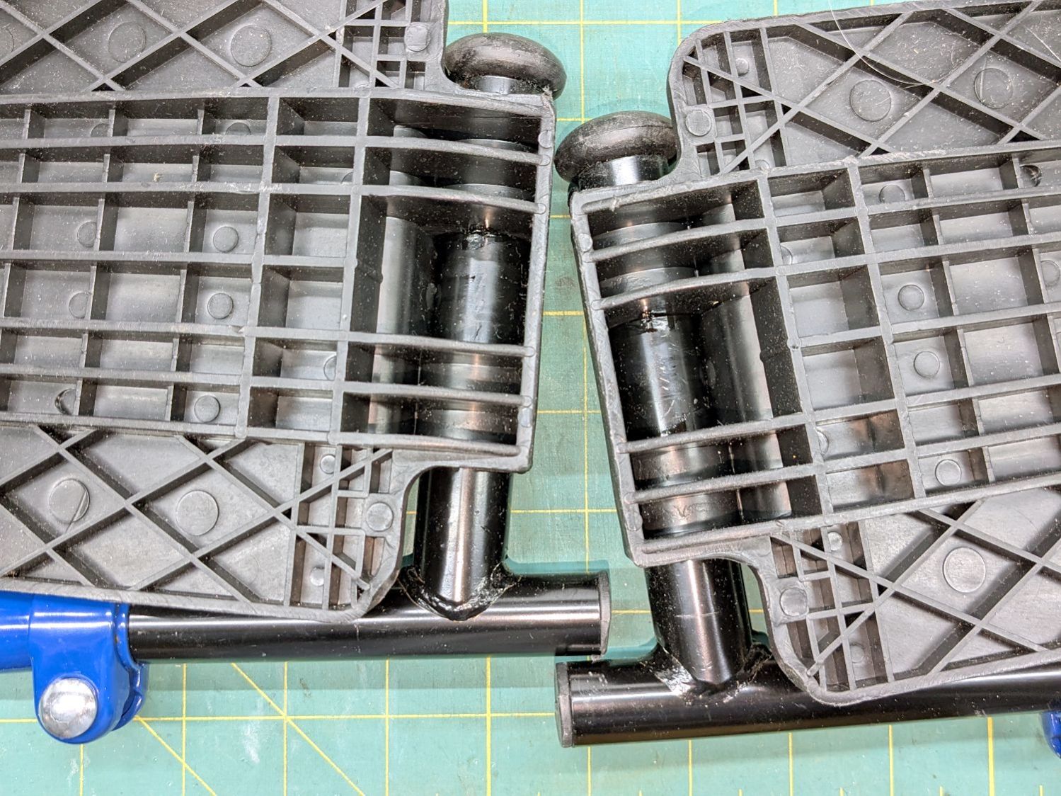
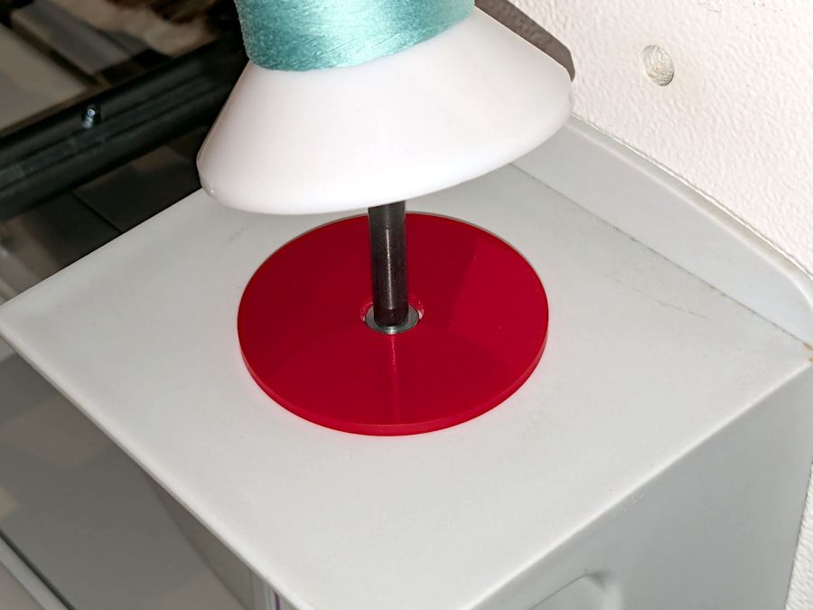
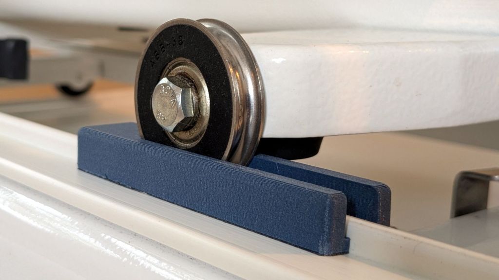
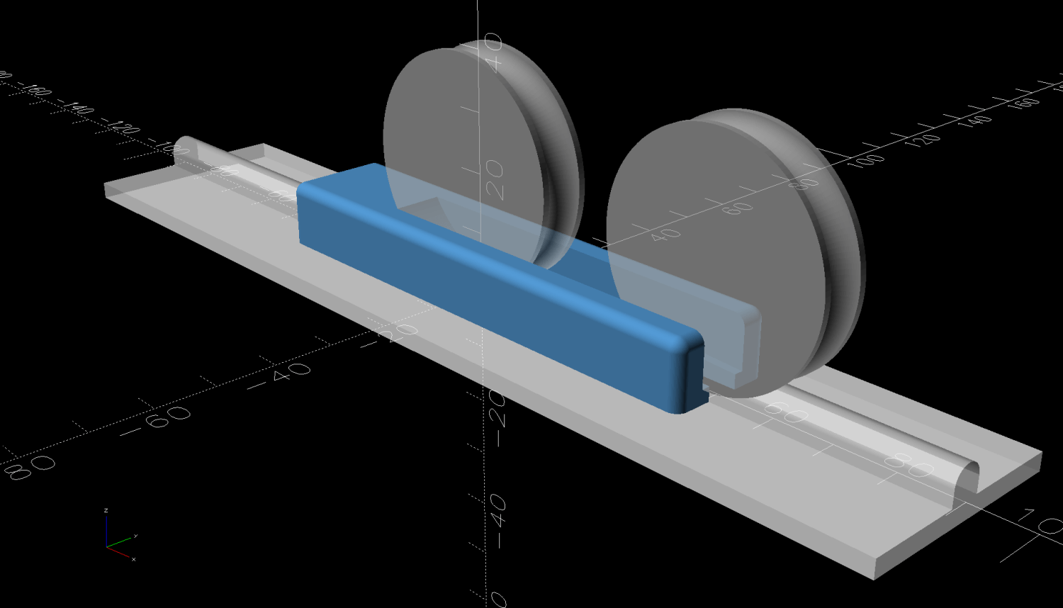
Duplicating those rings in a smaller size seemed both difficult and not obviously functional, so I built a pair of blocks to capture the wheel on its track:
The wheel sits in a recess holding it just barely above the track surface, so the (considerable) weight of the machine holds the block in place.
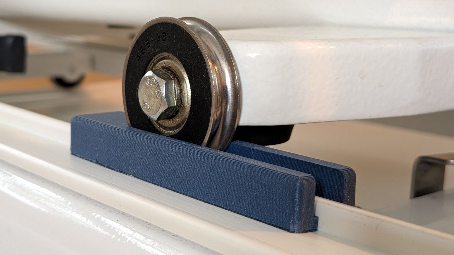
Because lines on quilts have precise placement and Mary has quilting rulers within reach, the block measures exactly two inches from the point where it first touches the wheel to the center of the recess:
She can then lay a ruler on the quilt, roll the machine front or back two inches, slide a block against each wheel, then roll the machine up a slight incline until the wheel drops into the recess:
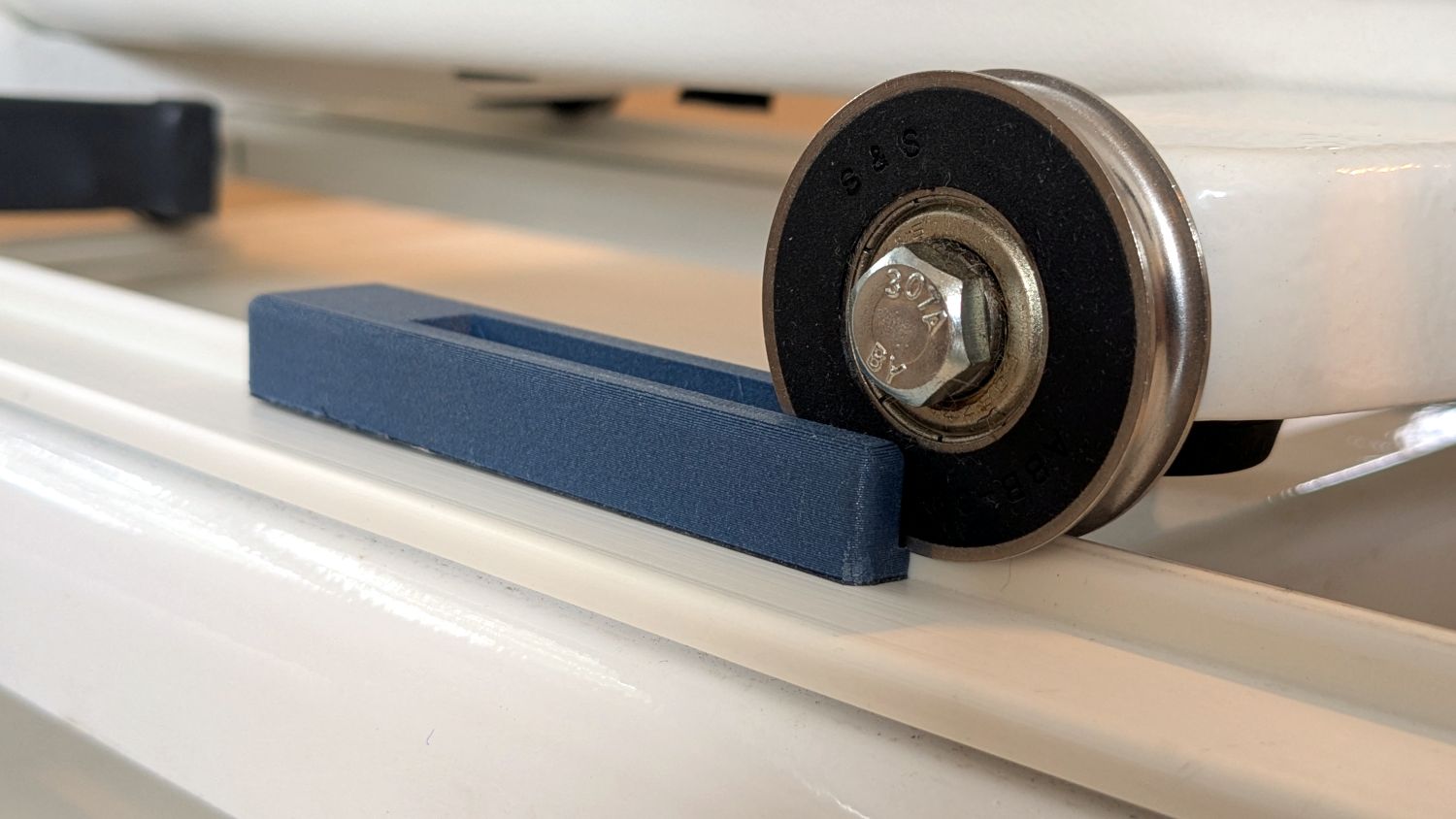
The spacing looks like this:
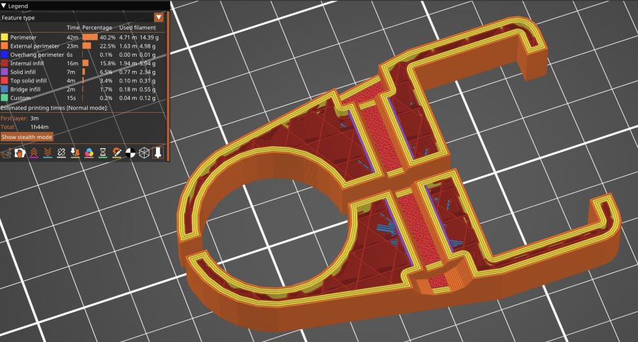
The usual 3D printing process puts 0.2 mm steps along the ramp, but they’re almost imperceptible while rolling the machine:
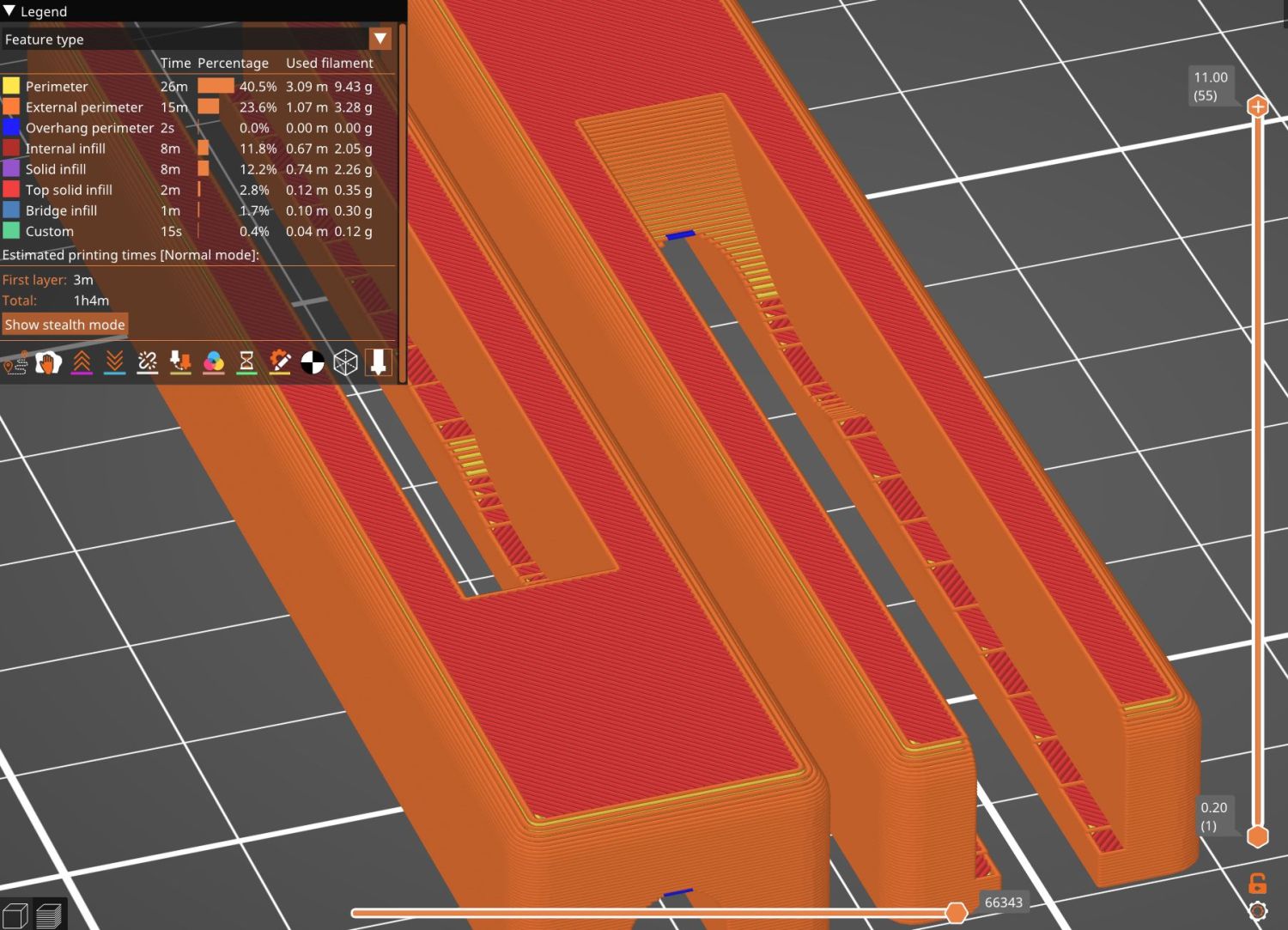
The ramp slope is all of 1:20 = 2.5°, so pulling / pushing the machine requires very little oomph.
I put thin cloth tape (approximately friction tape, but with real adhesive) on the bottom of the block by the simple expedient of sticking it to the block and scissoring off the excess. A little compliance between the block and the track prevents the hard plastic shapes from sliding more easily than I’d like. If your tape is thicker than mine, knock a little off the WheelZ value.
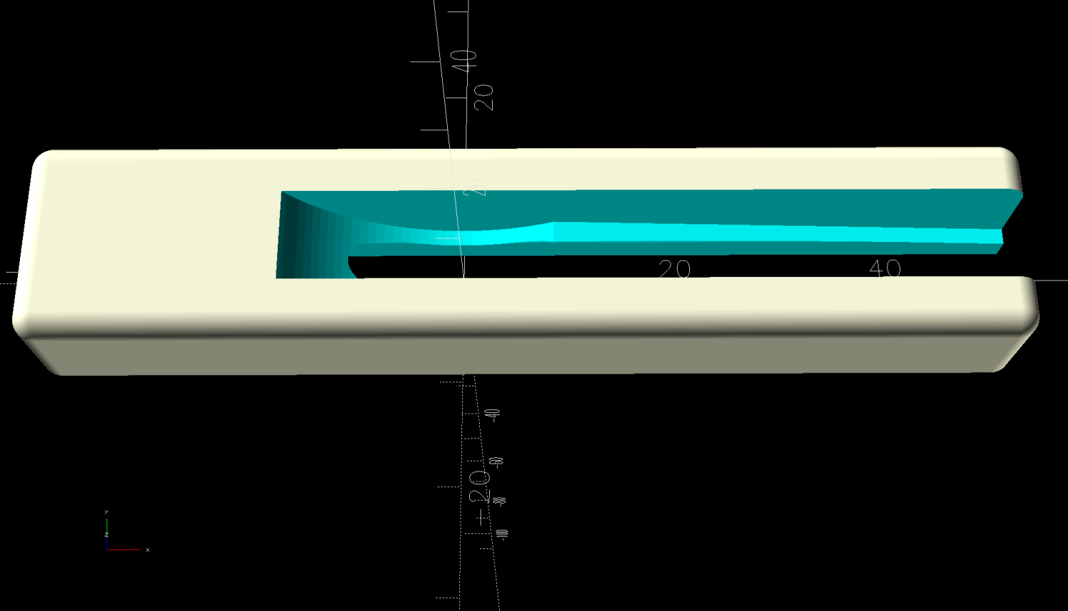
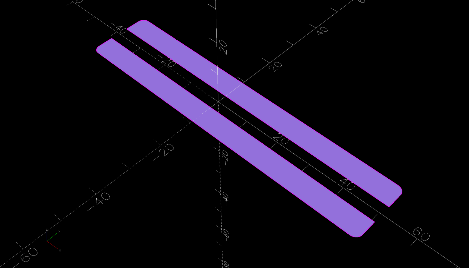
The OpenSCAD code can produce shapes to laser-cut an adhesive sheet, although stacking a foam sheet will definitely require height adjustment :
The OpenSCAD source code as a GitHub Gist:
| // HQ Sixteen – wheel track lock block | |
| // Ed Nisley – KE4ZNU | |
| // 2025-02-14 | |
| include <BOSL2/std.scad> | |
| Layout = "Show"; // [Show,Build,Glue,Track,Block,Wheel] | |
| /* [Hidden] */ | |
| ID = 0; | |
| OD = 1; | |
| LENGTH = 2; | |
| Protrusion = 0.1; | |
| Windage = 0.1; | |
| WallThick = 5.0; // minimum wall thickness | |
| RailOD = 5.5; // rounded top of rail | |
| RailHeight = RailOD; // … flange to top | |
| RailBase = [100,2*15.7 + RailOD,3]; // … Y = flange width, arbitrary X & Z | |
| WheelOD = 38.0; // rail roller | |
| WheelMinor = 6.2; // … rail recess | |
| WheelWidth = 8.3 + 2*Windage; // … outer sides | |
| WheelZ = RailHeight + (WheelOD – WheelMinor)/2; // axle centerline wrt rail flange | |
| LockOC = 2.0*INCH; // engagement to lock recess | |
| GripLength = 20.0; | |
| BlockOA = [GripLength + WheelOD/2 + LockOC,WheelWidth + 2*WallThick,2*RailHeight]; | |
| BlockRadius = 2.0; | |
| $fn = 12*3*4; // smooth outer perimeters | |
| //———- | |
| // Construct the pieces | |
| module Track(Len = 2*BlockOA.x) { | |
| zrot(90) back(Len/2) down(RailBase.z) xrot(90) | |
| linear_extrude(height=Len,convexity=5) | |
| rect([RailBase.y,RailBase.z],anchor=FRONT) | |
| attach(BACK,FRONT) rect([RailOD,RailHeight – RailOD/2]) | |
| attach(BACK) circle(d=RailOD); | |
| } | |
| module Wheel(Len = WheelWidth) { | |
| xrot(90) | |
| difference() { | |
| cylinder(d=WheelOD,h=Len,center=true); | |
| torus(r_maj=WheelOD/2,d_min=WheelMinor); | |
| } | |
| } | |
| module Block() { | |
| difference() { | |
| left(GripLength + WheelOD/2) | |
| cuboid(BlockOA,anchor=LEFT + BOTTOM,rounding=BlockRadius,except=BOTTOM); | |
| Track(); | |
| up(WheelZ) xrot(90) | |
| cylinder(d=WheelOD,h=WheelWidth,center=true); | |
| right(LockOC) | |
| up(WheelZ – WheelOD/2) yrot(atan((RailHeight – WheelMinor/2)/LockOC)) | |
| cuboid([LockOC,WheelWidth,BlockOA.z],anchor=RIGHT+BOTTOM); | |
| } | |
| } | |
| //———- | |
| // Show & build the results | |
| if (Layout == "Block" || Layout == "Build") | |
| Block(); | |
| if (Layout == "Track") | |
| Track(); | |
| if (Layout == "Wheel") | |
| Wheel(); | |
| if (Layout == "Glue") | |
| projection(cut=true) | |
| Block(); | |
| if (Layout == "Show") { | |
| color("SteelBlue") | |
| Block(); | |
| for (i=[0,1]) | |
| right(i*LockOC) | |
| color("Silver",0.7) | |
| up(WheelZ) Wheel(); | |
| color("White",0.5) | |
| Track(); | |
| } | |