Ed Nisley's Blog: Shop notes, electronics, firmware, machinery, 3D printing, laser cuttery, and curiosities. Contents: 100% human thinking, 0% AI slop.
Tag: Improvements
Making the world a better place, one piece at a time
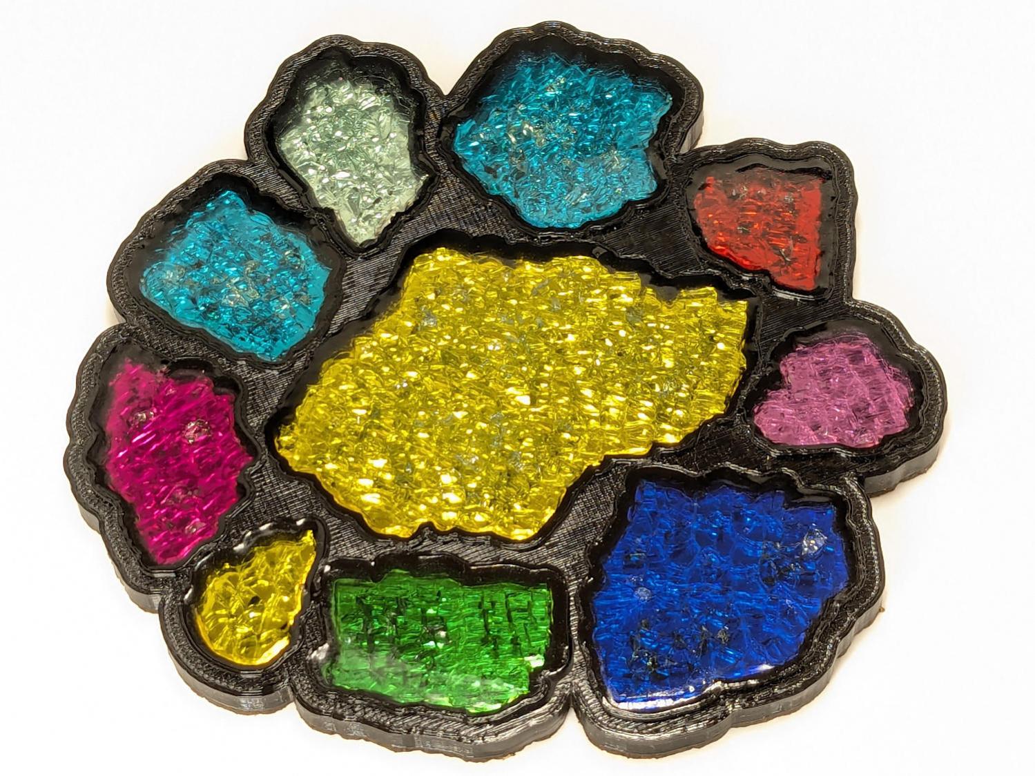
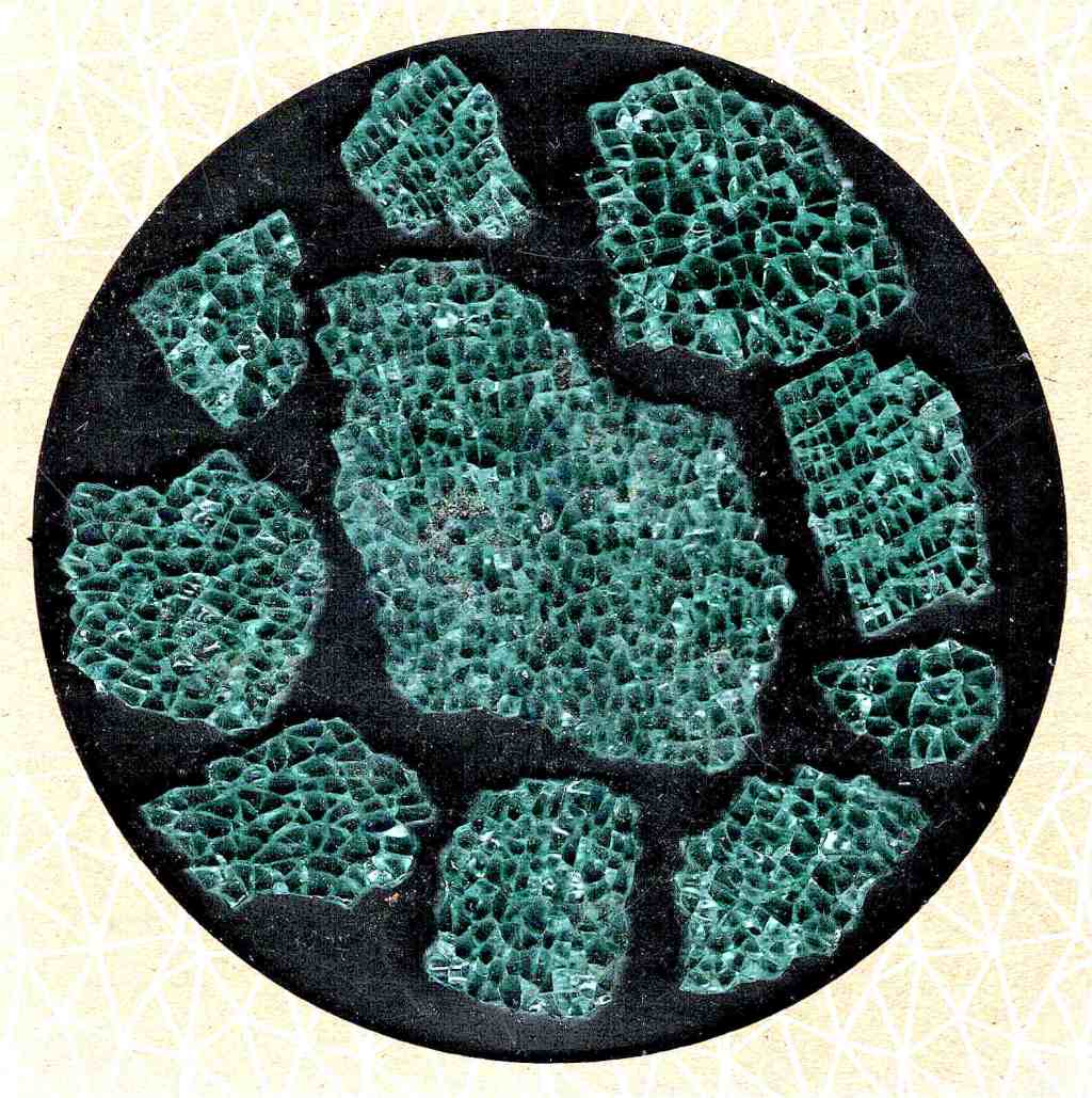
Having recently had to move the flat box of shattered glass to get something from behind it, I figured I could apply new techniques to old material :
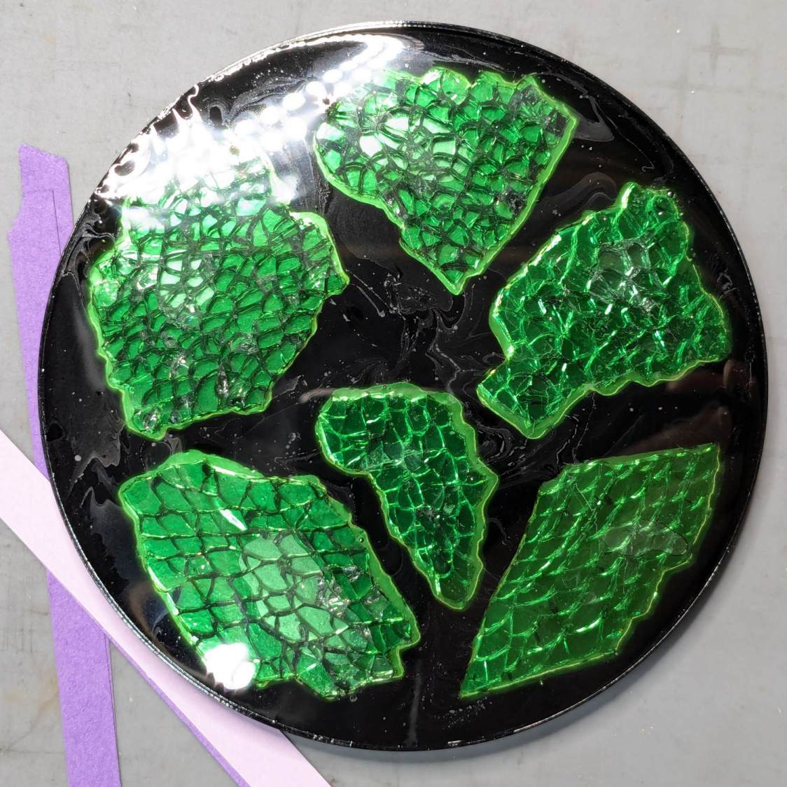
Smashed glass printed coaster – oblique view
This is something of a test case to restart the whole process, so it has a few bloopers. This post covers the results, with more detail on the process to follow.
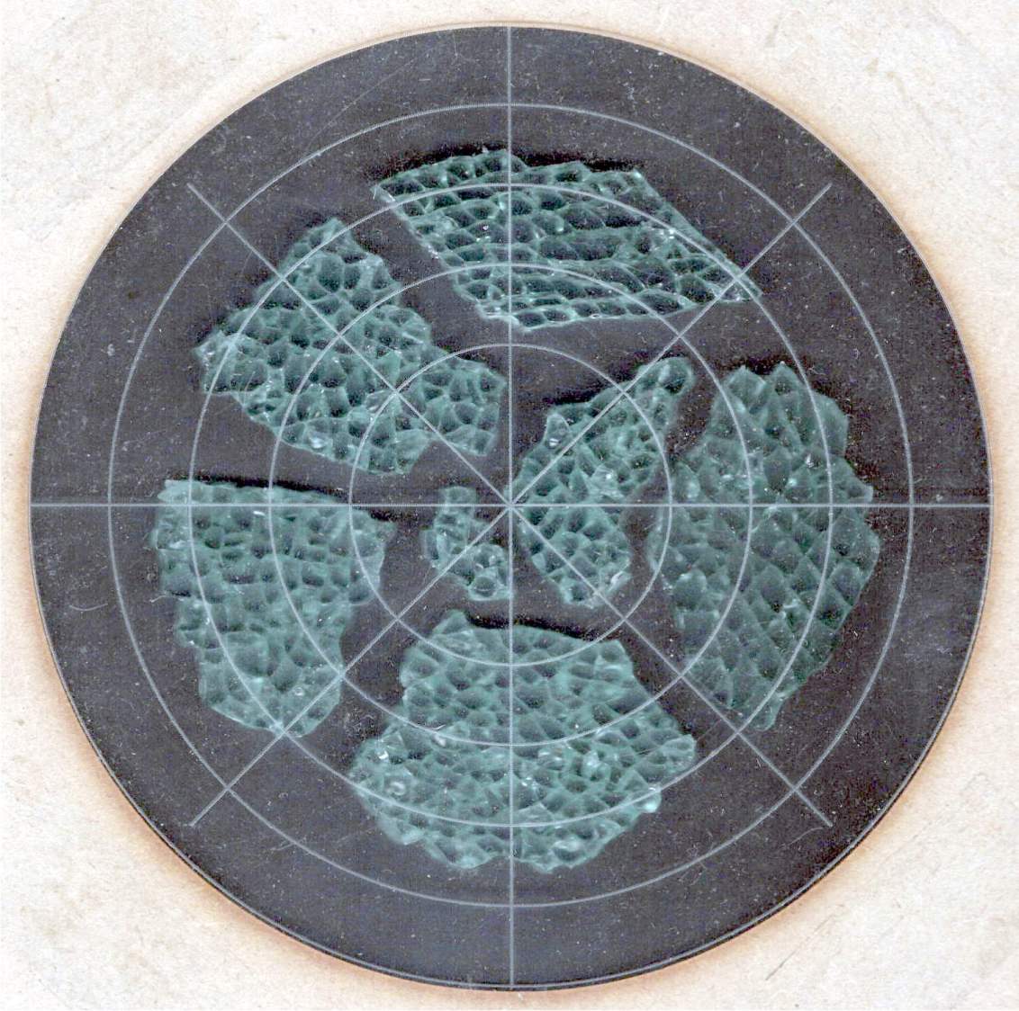
Arrange some good-looking shattered glass fragments within the 4 inch circle on the fixture:
Smashed glass printed coaster – fragment test fit
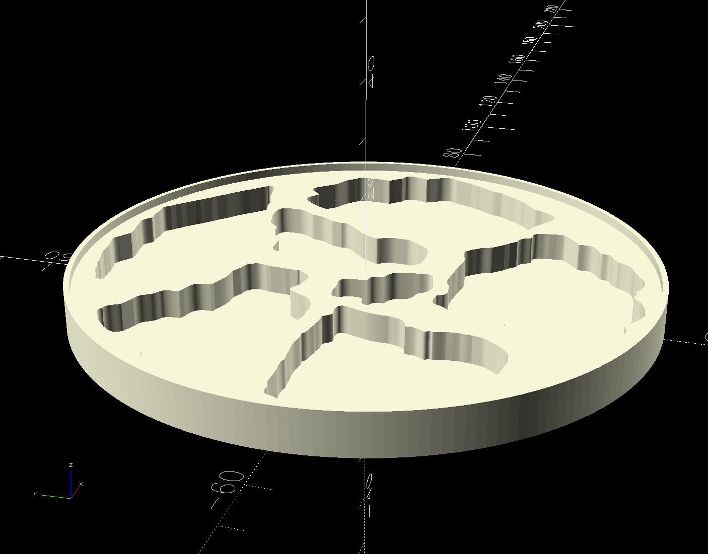
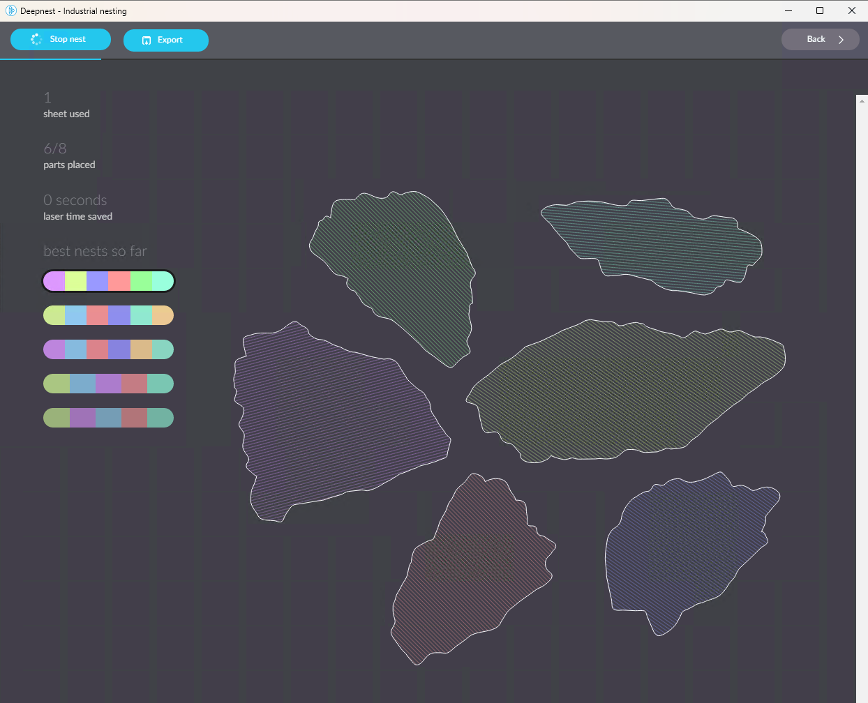
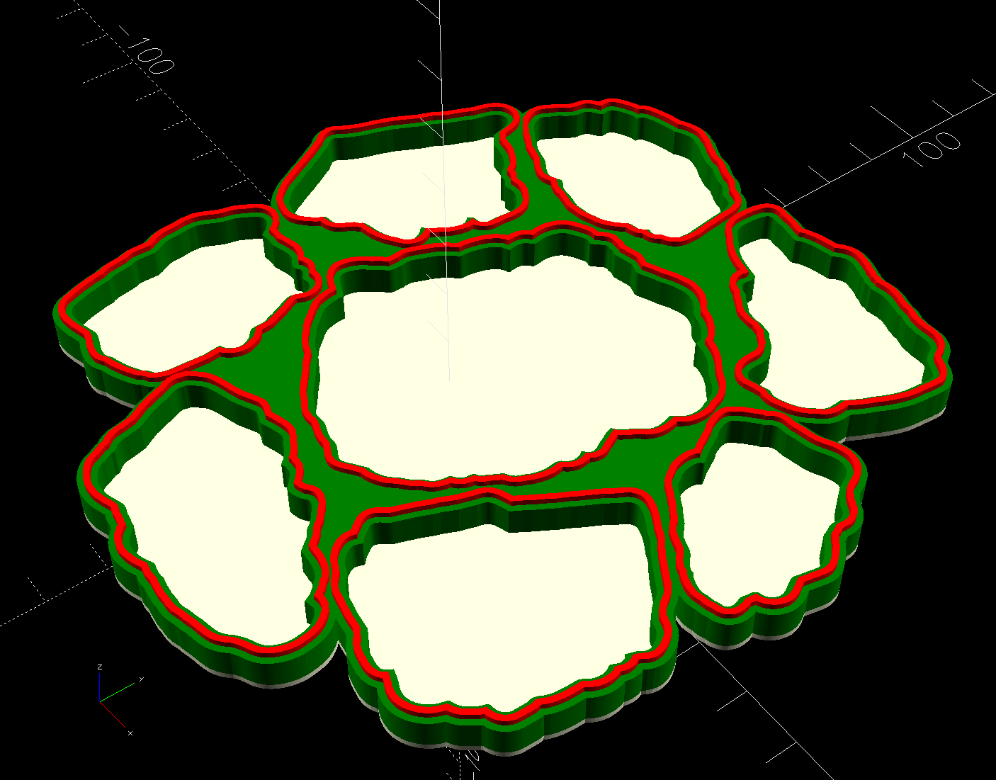
Scan it, trace the outlines into paths using GIMP, label the paths in Inkscape, import into LightBurn to laser-cut the chipboard disk in that picture to verify enough clearance around the fragments, import into OpenSCAD, and produce a solid model for PrusaSlicer:
Printed Coaster Layout – slicer
While it’s printing, laser-cut green metallized paper to serve as a reflecting layer below the glass, then affix the paper to the bottom of the recesses:
Smashed glass printed coaster – metallized paper assembly
During that process I discovered one of the fragment recesses didn’t make it from the Inkscape SVG file to the OpenSCAD model:
Smashed glass printed coaster – missing fragment
Like I said: bloopers. That fragment now has its place in the OpenSCAD code and the slicer preview above, not that I have matching fragments to build another one.
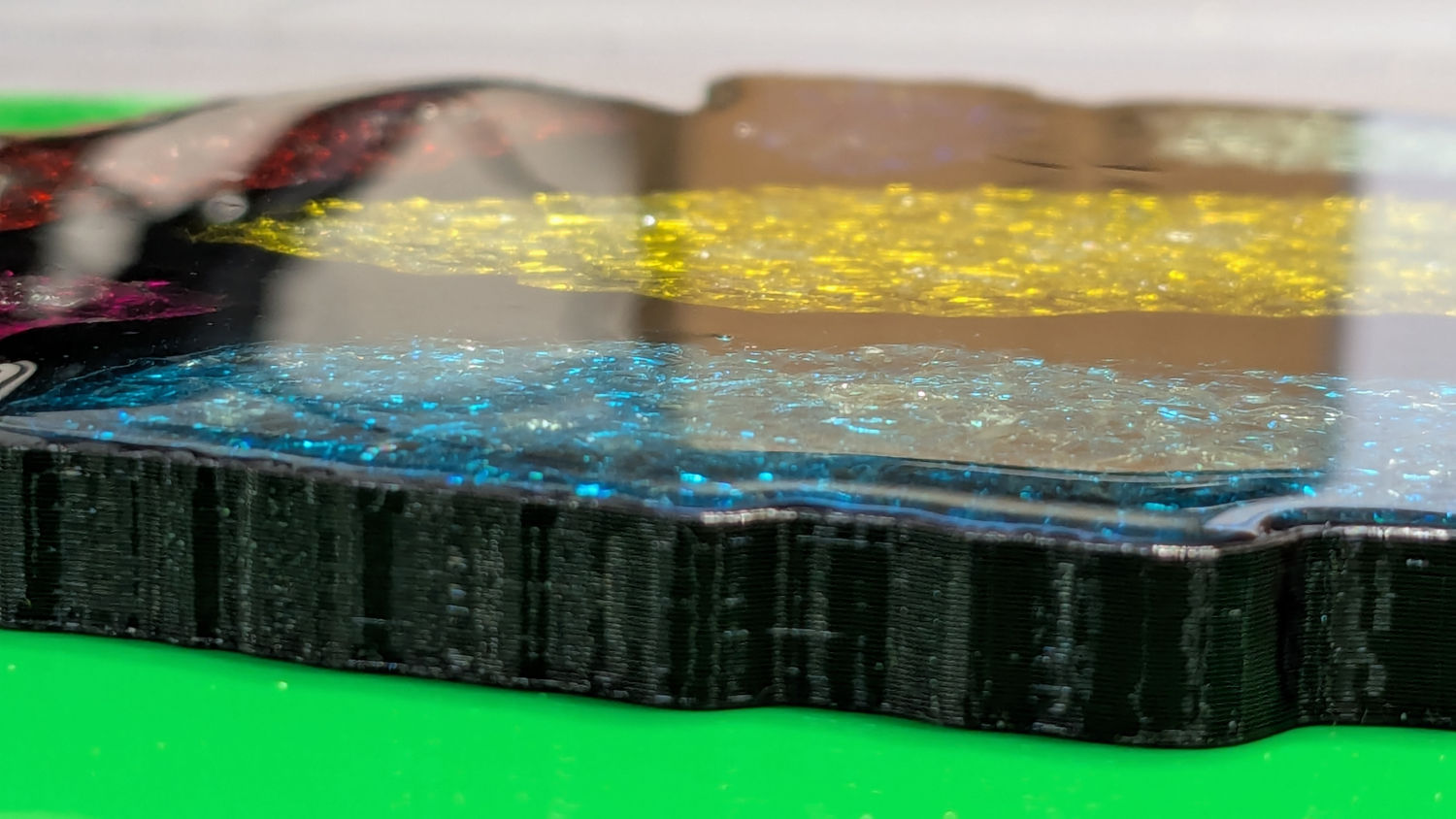
Put all but one fragment in their places, pour clear epoxy over everything, pop bubbles for a while, then let it cure overnight:
Smashed glass printed coaster – front view
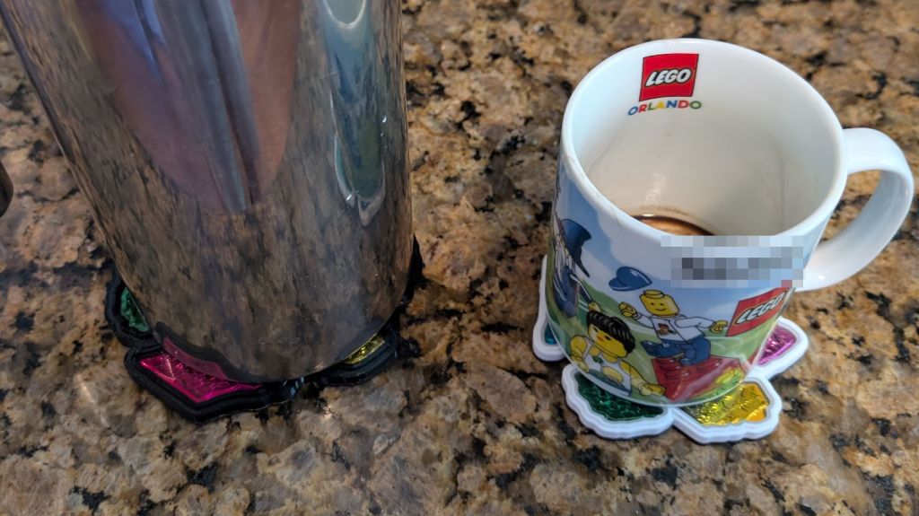
Stick a PSA cork disk on the bottom and it’s ready for service.
One of Mary’s gardening buddies gave her a Taylor rain gauge he picked up at a closeout sale, but the exceedingly thin aluminum holder obviously wasn’t up to the task:
Taylor Rain Gauge – OEM metal stake
I briefly considered 3D printing a better bracket, but came to my senses:
Taylor Rain Gauge holder – front
A generous fillet of tan JB PlasticBonder holds the thin aluminum clamp ring to the top of the dagger spike:
Taylor Rain Gauge holder – rear
The spike is 6.3 mm acrylic and should survive for a while despite the stress-raiser corners. The next iteration will have radiused corners and could last longer:
Taylor Rain Gauge Holder – LightBurn layout
The holes will fit 4 mm screws, although the OEM holder isn’t good for more than 3 mm.
Run the program ten times to generate ten SVG images:
for i in {00..09} ; do python Layers\ -\ 24x18.py --layernum=$i --colors=9 > Test_$i.svg ; done
The LightBurn layout dwarfs the machine platform:
Layered Paper – circular colors – 24x18in – LightBurn layout
Fire The Laser ten times and you get a wall hanging:
Layered Paper – 24×18 – trial alignment
That’s a trial alignment atop a cardboard box on the Basement Shop floor, because gluing those 24×18 inch sheets of paper requires time on the Sewing Table, which is currently occupied by a much higher priority project. The brown innermost circle in the design is entirely separate from the brown Amazon cardboard box underneath everything.
Fairly obviously, you’d want something other than brown at the focal point of that design, but following the EIA color code gives me some confidence the result matches the intention. Feel free to tart it up with your own colors.
I laid a 29×23 inch sheet of sketch paper on the honeycomb, distributed neodymium bar magnets around the perimeter, and cut a 24×18 rectangle out of the middle:
Layered Paper – 24×18 – brown squares
Those squares are the cutouts from the brown sheet, minus what you see in the lead picture.
The black rectangle on the left of the LightBurn layout above is the 24×18 inch cut for the fixture. Centering that rectangle on the LightBurn layout (click-select, Ctrl-D to duplicate, then hit P to move it to the center) means aligning each of the ten patterns requires nothing more than the same click-select / dupe / P, with no delicate fiddling.
Then just lay each colored sheet into the hole and it’s properly aligned. Because the machine homes to the same physical location every time it’s turned on and the fixture is mmm fixed to the platform, cutting all ten sheets over the course of two days proceeded smoothly.
Cutting 2537 holes in the black mask takes a little under an hour:
Layered Paper – 24×18 – cutting black
The other sheets have fewer holes and go progressively faster:
Layered Paper – 24×18 – cutting yellow
The white sheet on the bottom has four alignment holes and four layer ID holes, so the cuts take a few seconds.
Thresholding the distance from a randomly chosen point creates circular rainbows:
CenterPoint = (choice(range(args.width)),choice(range(args.height)))
CellMatrix = [[math.hypot(x - CenterPoint[X],y - CenterPoint[Y])
for y in range(args.height)]
for x in range(args.width)]
dmax = max(list(chain.from_iterable(CellMatrix)))
LayerThreshold = (ThisLayer/Layers)*dmax
The Python program generates one SVG image file representing a single layer, as determined by the Bash one-liner invoking it:
for i in {00..16} ; do python Layers\ -\ 200mm.py > Test_$i.svg ; done
In real life you’d also use a different random seed for each set of layers, but that’s just another command line optIon.
Import those 17 SVG images into LightBurn, arrange neatly, snap each one to the middle of the workspace grid (and thus the aligned template), then Fire The Laser:
Feeding paper into the laser in rainbow (actually, heavily augmented / infilled EIA color code) order, plus the black mask, produces the aforementioned pleasing result:
Layered Paper – rainbow oblique view
Glue the sheets in the assembly fixture:
Layered Paper – gluing fixture side view
The white layer is uncut, other than the four alignment holes (with a rivnut poking up) and its binary layer number (16, backwards because upside-down), and appears in only the farthest corners of the rainbow.
Protip: doing the stack upside-down means you smear glue stick on the hidden side of each sheet. If you avoid slobbering glue into the cut square holes, nothing can go wrong.
Making these things produces the happiest chip tray ever:
Layered Paper – rainbow chip tray
I swept half a dozen pictures worth of squares into a small box and gave it away to someone with a larger small-child cross-section than mine, whereupon a slight finger fumble turned the contents into a glitter bomb. Sorry ’bout that.
This file contains hidden or bidirectional Unicode text that may be interpreted or compiled differently than what appears below. To review, open the file in an editor that reveals hidden Unicode characters.
Learn more about bidirectional Unicode characters
# cut layer ID holes except on mask layer
if ThisLayer > 0:
c = ((1,1))
h = f'{ThisLayer:0{Layers.bit_length()}b}'
for i in range(Layers.bit_length()):
SheetEls.append(
svg.Circle(
cx=as_mm(SheetCenter[X] + c[X]*AlignOC[X]/2 - (i + 2)*AlignOD),
cy=as_mm(SheetCenter[Y] + c[Y]*AlignOC[Y]/2),
r=AlignOD/4 if h[-(i + 1)] == '1' else AlignOD/8,
stroke=SheetCut,
stroke_width=DefStroke,
fill="none",
)
)
Filling the matrix of blocks with random numbers turned out to be a one-liner:
CellMatrix = [[randint(1,args.colors) for _ in range(args.height)] for _ in range(args.width)]
That matrix is a constant for all the layers, which is why you must feed the program the same random number seed to generate the layers.
Given the layer number and that matrix, deciding what to do for each hole is a walk through the cells:
MatrixEls = [] # accumulates matrix cuts
for i in range(args.width):
x =i*CellOC[X]
for j in range(args.height):
y = j*CellOC[Y]
if ThisLayer == 0: # black mask
s = HeavyCellCut
elif ThisLayer < CellMatrix[i][j]: # rest of sheets above color layer
s = CellCut
else:
s = Tooling # at or below color layer
MatrixEls.append(
svg.Rect(
x=as_mm(SheetCenter[X] - MatrixOA[X]/2 + x),
y=as_mm(SheetCenter[Y] - MatrixOA[Y]/2 + y),
width=as_mm(CellSize[X]),
height=as_mm(CellSize[Y]),
stroke=s,
stroke_width=DefStroke,
fill="none",
)
)
After accumulating all the other elements in similar lists, this creates and emits the entire SVG file to stdout:
The whole program has a bit more going on, but those are the high points.
Invoke the program with a Bash one-liner:
for i in {00..08} ; do python Layers.py --layernum=$i > Test_$i.svg ; done
That produces nine SVG image files that you import into LightBurn and arrange in a tidy array:
Layered Paper – Random Blocks – MVP – LightBurn import
I discovered that holding down the Shift key while importing the SVG files stacks them at the workspace origin (the upper-right corner for my machine) in the order of the file names, so clicking on the stack selects successive layers in the right order; just drop each one wherever you need it, then tidy the lineup.
The Python program sets the vector stroke colors using LightBurn palette values, so that LightBurn automagically assigns them to the appropriate layers. It turns out the black paper I used for the mask requires different speed / power values than the other colored paper.
I put the alignment features on a different layer than the matrix holes to make them more visible, even though they have the same speed / power values.
Align the template so the middle of the layer pattern is in the middle of the grid, then use LightBurn’s Print and Cut to align the template with the fixture on the laser platform:
Layered Paper – Random Blocks – MVP – template
Then the process requires just a few clicks per layer:
Drop a sheet of paper into the fixture
Click to select a layer layout
Ctrl-D to duplicate it
P to snap it to the middle of the grid
Alt-S to Fire The Laser
Del to delete that layer (which is why it’s a duplicate!)
Iterate until done!
Which looks pretty much like you’d expect:
Layered Paper – Random Blocks – cutting
Take the stack of paper to the workbench, use an Xacto knife to cut the tabs holding the square into the Letter page, apply glue stick, stack in the fixture, and iterate to create a solid sheet with lots of holes:
Layered Paper – Random Blocks – MVP
More refinement is in order, but that’s the overview …
So they’re all set up with 25 g of fresh silica gel, although the boxes no long have the same humidity meters they started with. This likely makes little difference, as I have no way to calibrate them.
The CNC-3018XL fit into its new home with the Run/Hold buttons toward the front:
3018CNC – new orientation
Which is rotated 180° from its previous orientation, putting Quadrant I and the most-positive coordinates in the left-front corner. Rather than stand on my head while trying to use the jog keypad upside-down, I reversed the axis directions by changing the GRBL Direction port invert mask value from its previous 4:
$3=7
Because the home switch positions haven’t changed, reverse the Homing dir invert mask from 0:
$23=3
The XY origin remains in the center of the platform, so the G54 XY offset didn’t change. The Z offset puts the Pilot pen tip 10 mm above the platform, which will change as you (well, I) touch it off on the paper:
G10 L2 P1 X-169.0 Y-149.5 Z-44.0
Jog to the left rear corner (with Z at the home position) and set the G28 park position:
G28.1
Jog to the right front corner (also Z homed) where (manual) tool changes take place:
G30.1
Configure bCNC for manual tool changes without probing at the G30 position:
bCNC probe config
The machine will move to the tool change position at each Tn M6, the operator (that would be me) inserts tool pen n as needed, pokes the Run button, and watches it draw pretty pictures in a resolutely techie manner: