Ed Nisley's Blog: Shop notes, electronics, firmware, machinery, 3D printing, laser cuttery, and curiosities. Contents: 100% human thinking, 0% AI slop.
Tag: Improvements
Making the world a better place, one piece at a time
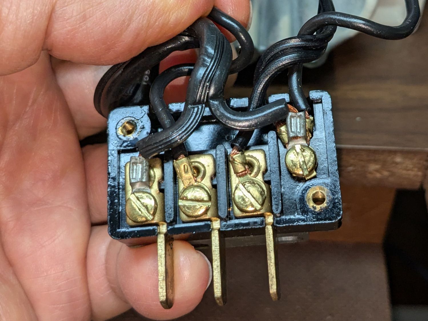
For the record, this is inside the machine’s power connector:
Kenmore 158 – power connector wiring
Power for the original glowworm incandescent light comes from the two rightmost terminals: 120 VAC switched by the machine’s power button. Those terminals now go to a new, much more flexy, cable for the 12 VDC power supply, with a step-up supply for the needle LEDs.
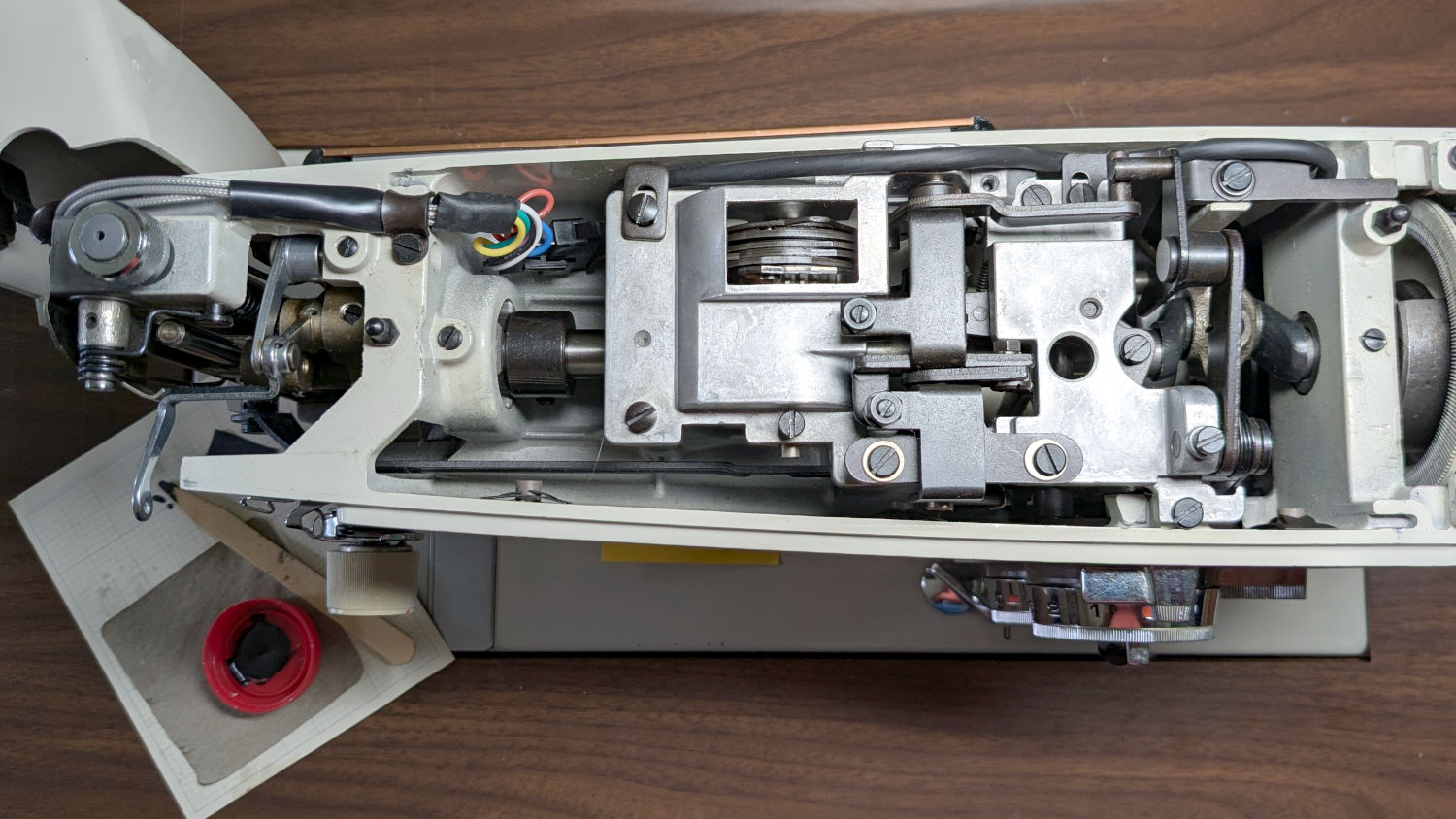
An overview of the wire routing:
Kenmore 158 – COB LED wire routing
There’s now a 9-pin JST SM connector between the repurposed serial cable and the LEDs, mostly so I can add another light bar to the front in the unlikely event it becomes necessary.
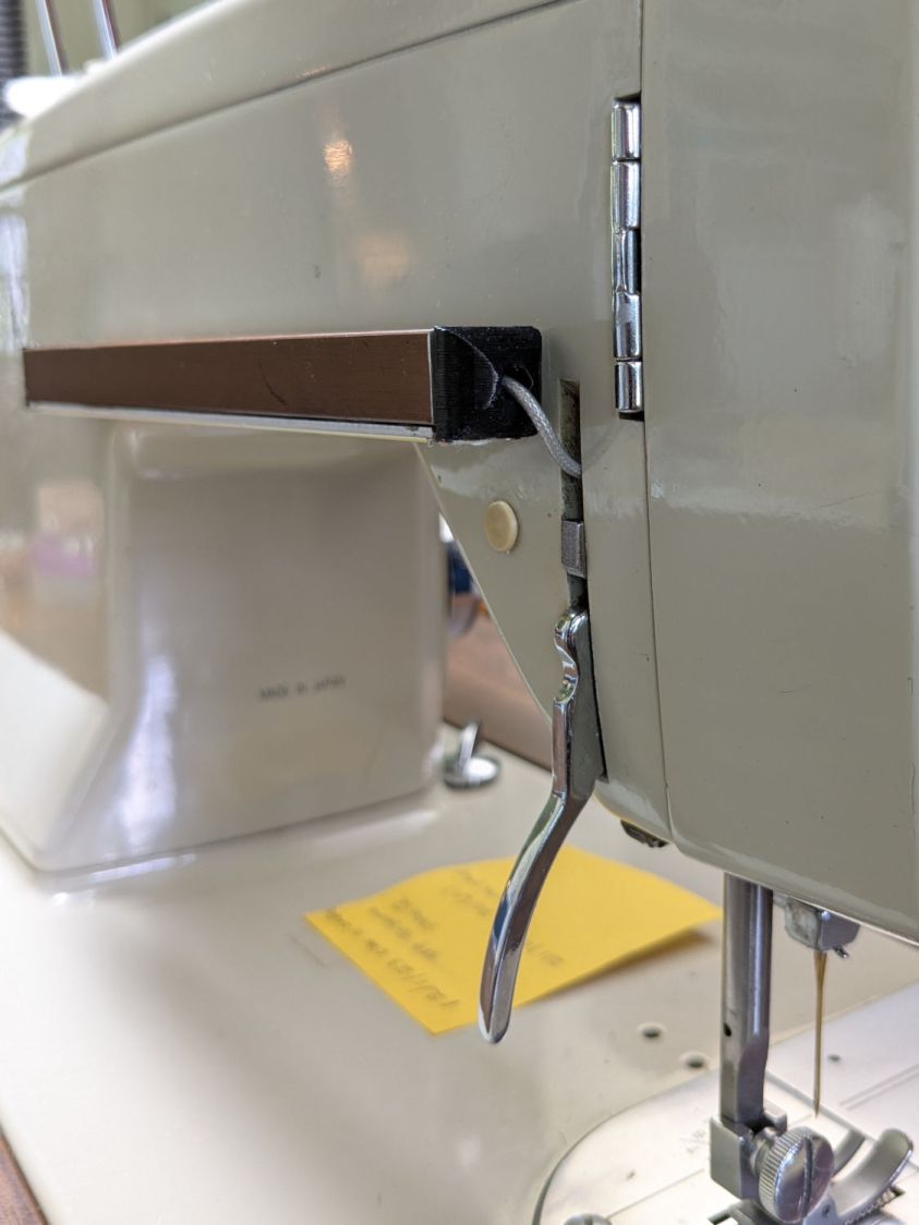
The rear light bar wire once again burrows into the machine above the presser foot lever:
Kenmore 158 – COB LED bar wire routing
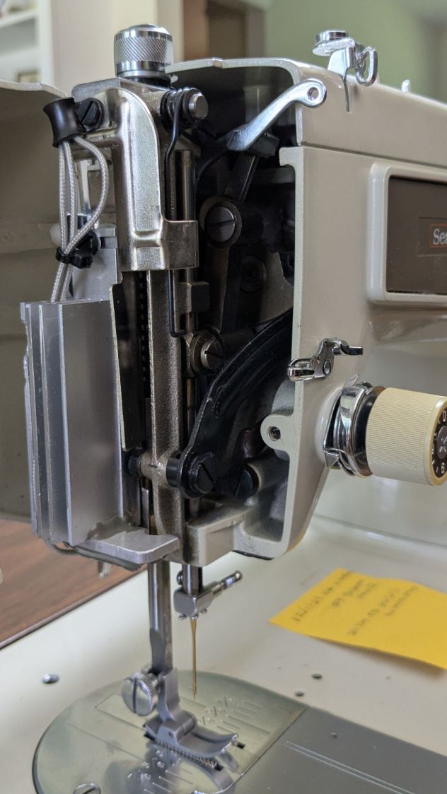
All the LED wiring fans out through the endcap:
Kenmore 158 – COB LED needle heatsink
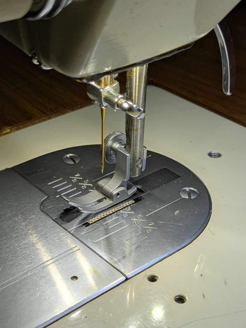
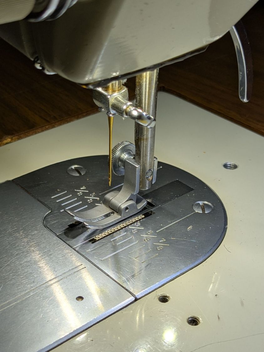
You can just barely see the edge of the strip of LEDs epoxied to the bottom of the machine nose, on the right of the needle.
If I were inclined to rebuild the needle LEDs, I’d use flexy silicone wiring instead of the Teflon insulated coax. The black insulation wouldn’t be nearly as pretty, but it’d be *way* easier to cut to length and solder.
The patient survived the operation and sewing should resume shortly …
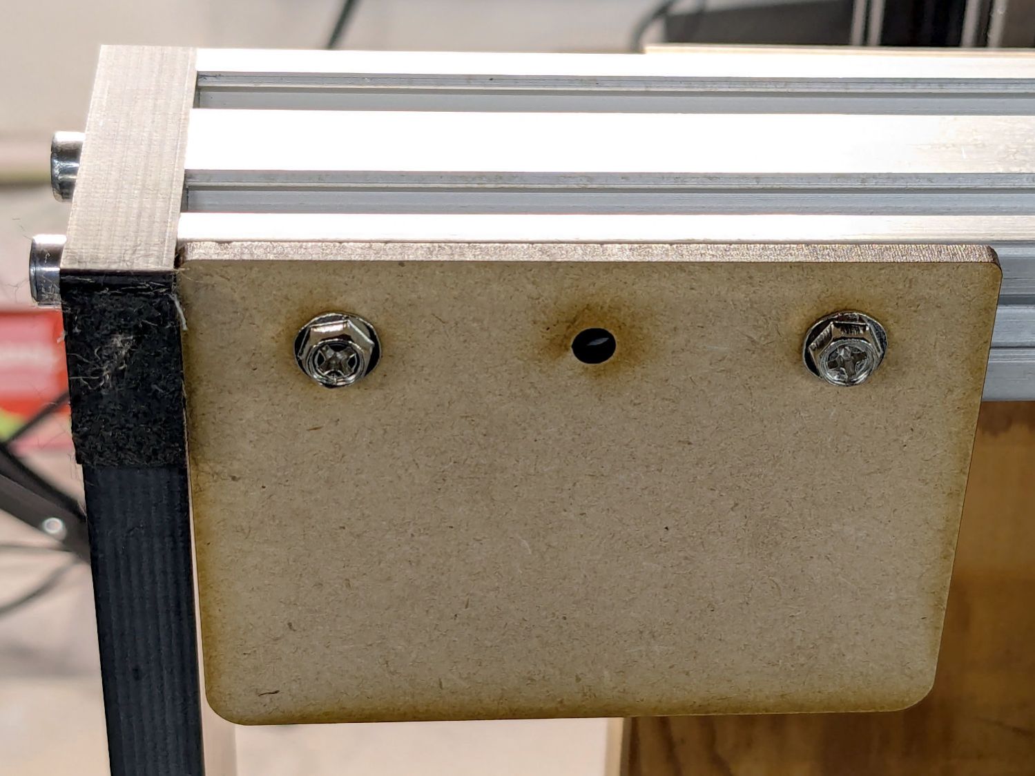
The 3018XL plotter now lives on a different bench than it grew up on and the stepper motors resonate the plywood benchtop wonderfully well. After finding the machine weighs enough to flatten small foam blocks under the Official Feet, I cut out four 60×80 mm foot pad brackets:
3018XL – foam foot pad bracket
They’re attached to the 2040 frame extrusions with M4 screws into tee nuts; the third hole is there just in case it became necessary. I’m not sure whether MDF will bend under that offset load, but having all four brackets perfectly fit into two pieces of MDF left over from previous projects was a compelling justification.
Some utility knife work produced the foam pads from a big sheet of polyethylene packing material:
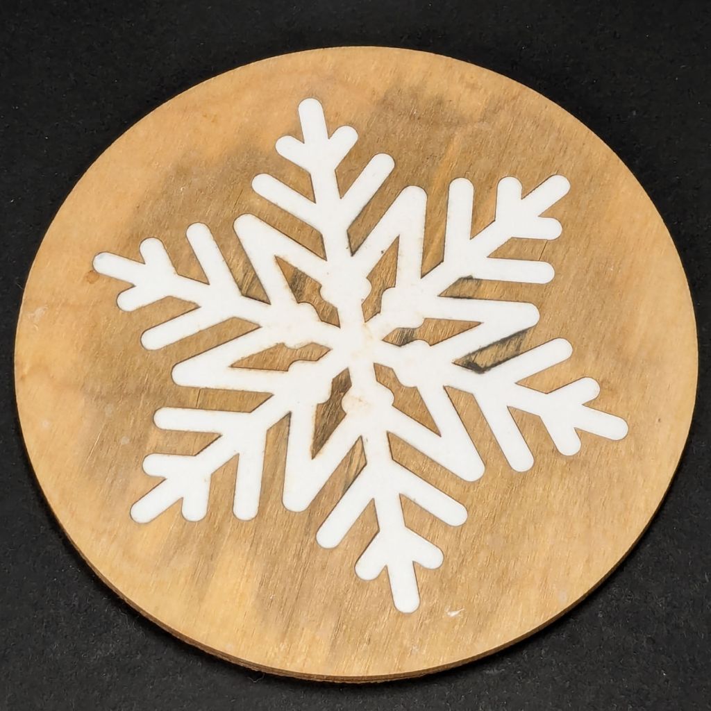
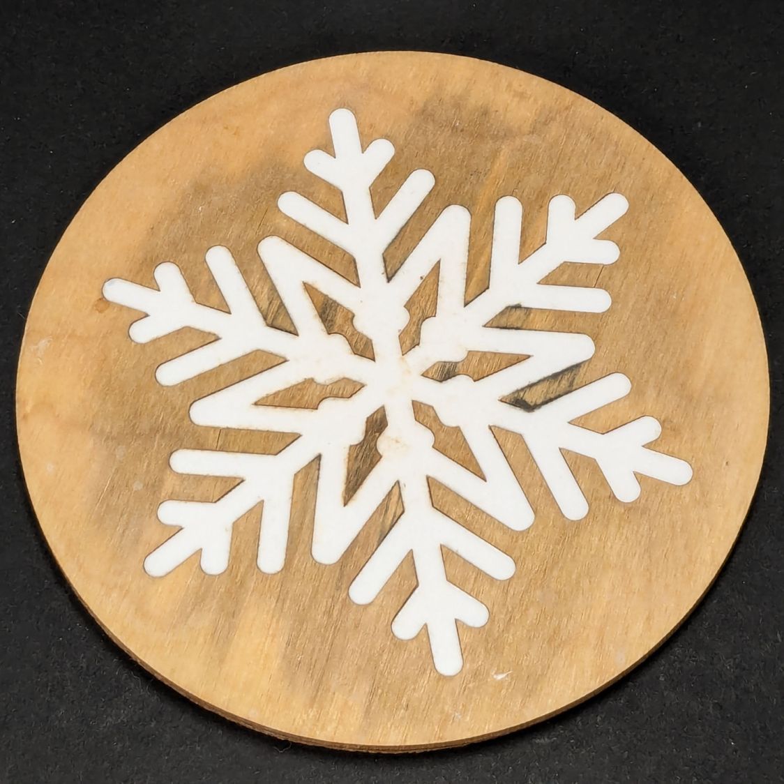
After more-or-less constant use under a cup in the bathroom, a Snowflake Coaster has reached the end of its life:
Snowflake coaster – 1 yr use
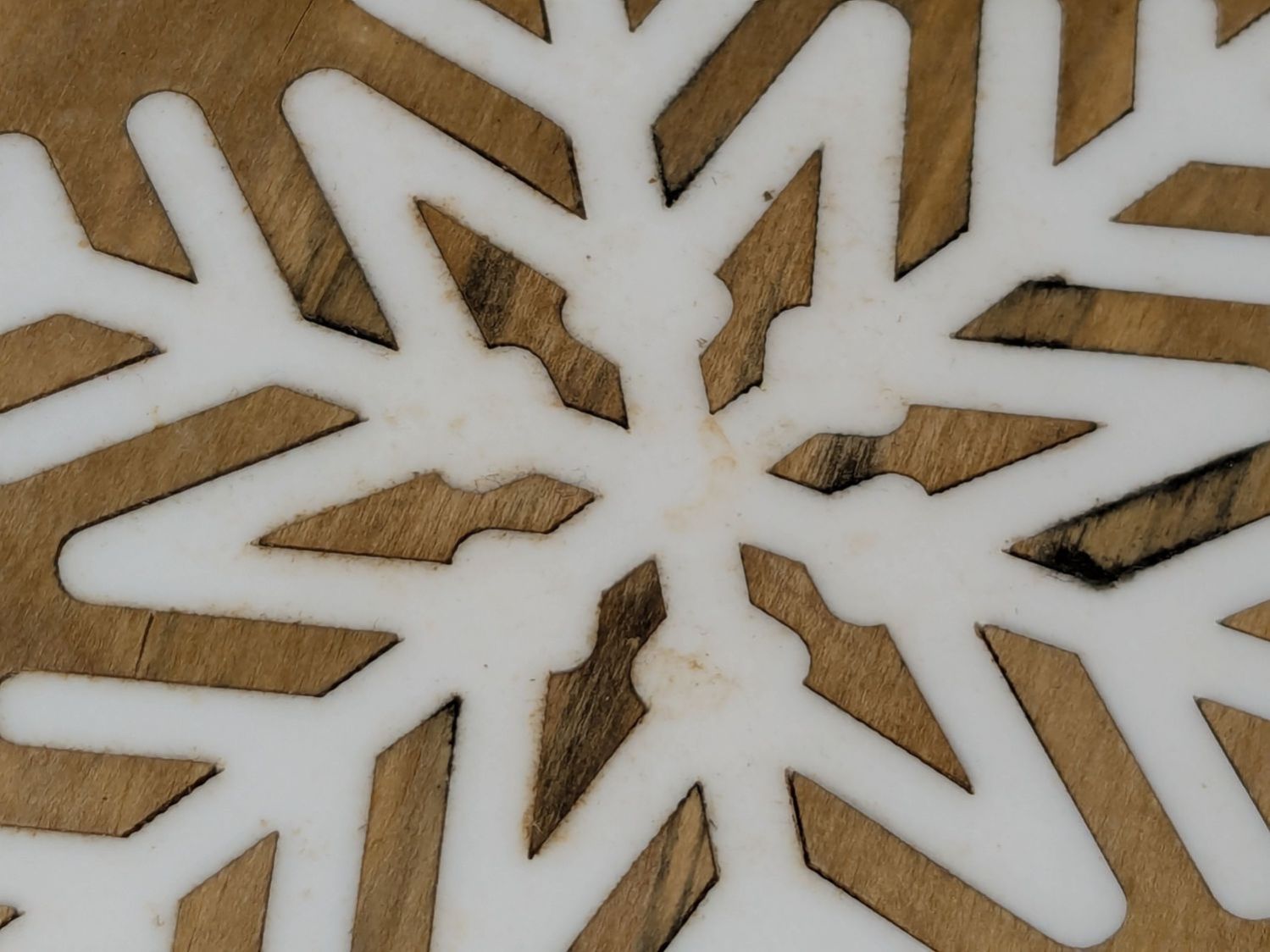
The acrylic flake is fine, but the wood has mildewed:
Snowflake coaster – 1 yr use – detail
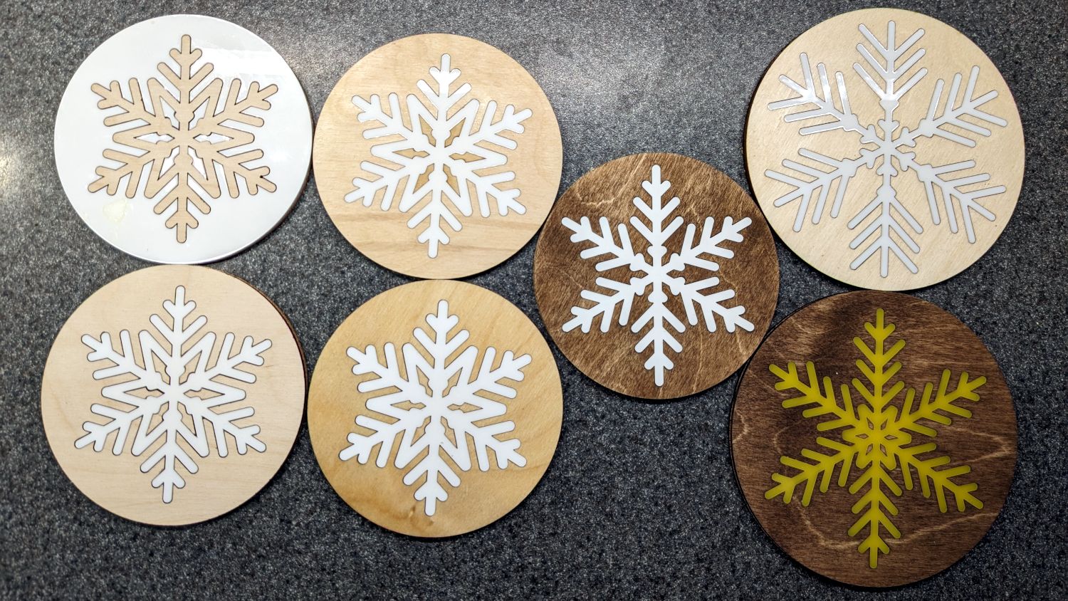
It’s second from the left in the bottom row:
Snowflake Coaster – assortment
All except the pair in the left column had a coat or two of rattlecan clear, which suggests wood-ish coasters need something much more durable, along the lines of clearcoat epoxy. No surprise there!
The bushes & trees along the Dutchess Rail Trail were reaching out to touch us again, so I took some slow rides with many stops.
Maple Oak trees along Page Park Drive:
DCRT Brush Trimming – oak – 2025-07
Blackthorn encroaching through the fence at Overocker:
DCRT Brush Trimming – blackthorn – 2025-07
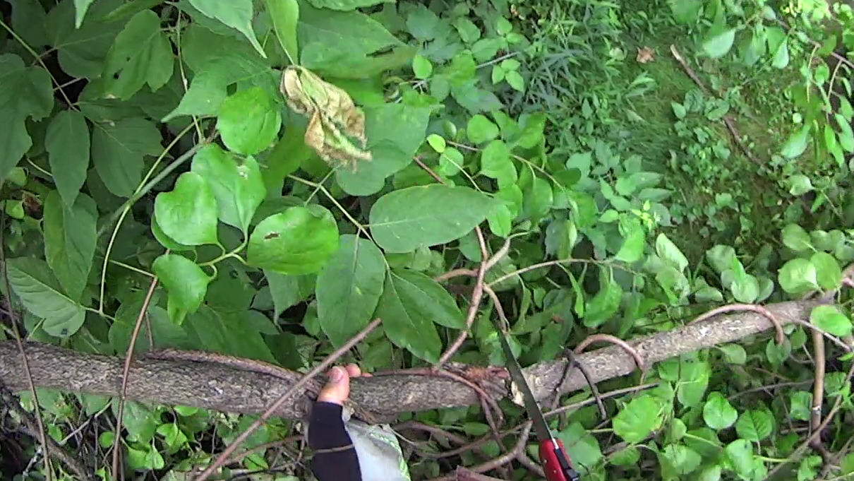
A tree somebody tossed down the trail bank near Morgan Lake:
DCRT Brush Trimming – discarded tree – 2025-07
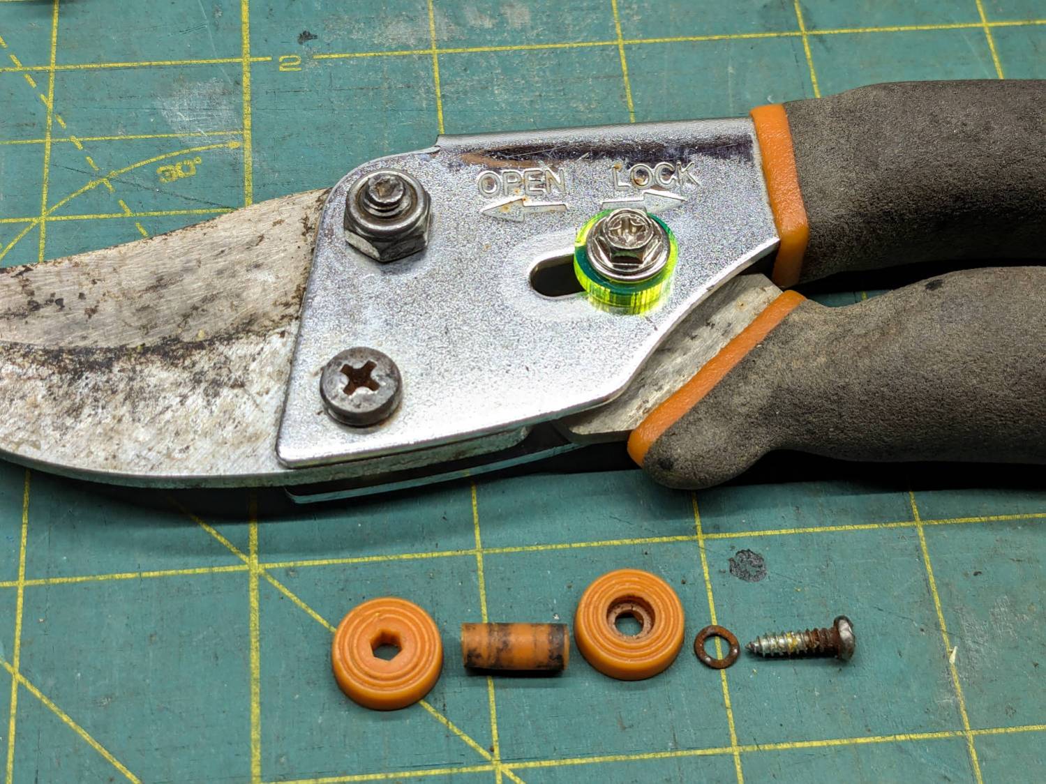
The slide lock on my trusty rehabilitated Fiskars bypass pruner worked loose and began sliding into the LOCK position when held overhead, then fell apart during disassembly:
Fiskars pruner – lock rebuild
The lock now consists of:
An M4 × 12 mm nut from a Chicago Screw that exactly matched the 5 mm OD cylinder passing through the pruner body
A laser-cut fluorescent acrylic disk for thumb grippiness
A washer just because
An M4 hex-head screw
A dab of Loctite bonding screw to nut
Clean the blades with alcohol and it’s ready for the rest of the season.
I should have put a wave washer in the stack for some springiness, but it works surprisingly well for what it is.
Now: discover how long acrylic lasts out there in the wild.
Update: Yeah, the lock needed a wave washer for more friction, which became apparent after the first overhead branch.
After fixing the X axis drive, the CNC-3018XL table moved properly again, so I measured its overall alignment:
3018CNC – table height measurement
The +Y side (on the left in the photo, keeping in mind I’ve rotated the axes) turned out to be 0.7 mm too low, so I made a set of riser blocks to level the tabletop:
Table Riser – solid model
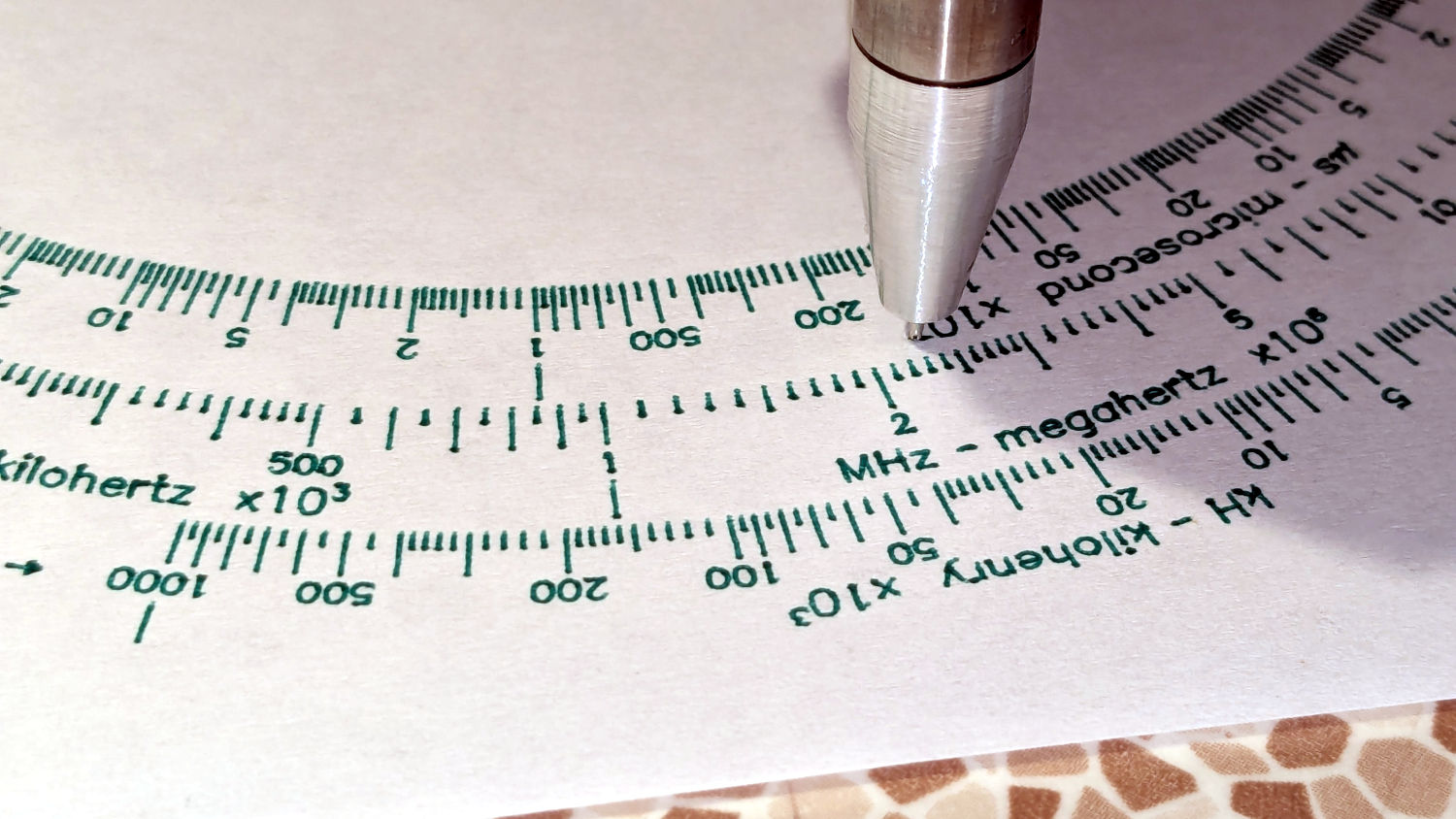
The 10 mm height would ram the tip of a Pilot pen about 10 mm below the tabletop surface, were it not for the spring-loaded pen holder:
Pilot V5RT holder – installed
The 0.7 mm difference in height levels the tabletop:
CNC3018XL – table riser positions
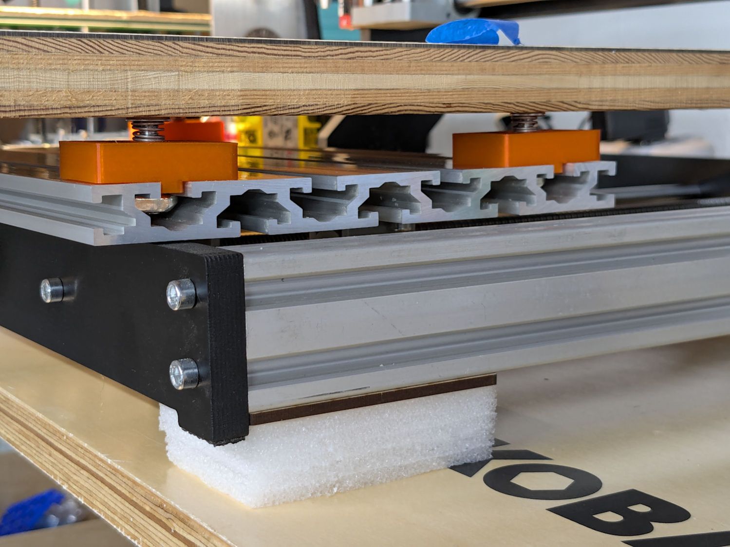
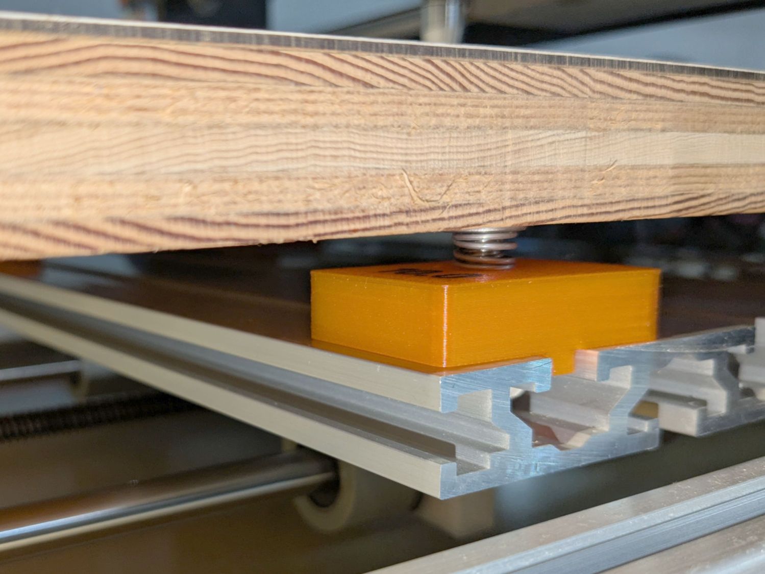
The OpenSCAD code produces an SVG outline I intended to use for a foam pad, but then I found a quartet of springs that worked even better:
CNC3018XL – table spring mount
So it’s now aligned within ±0.3-ish mm across the surface, with the unflatness of a slab cut from a 1955-era Formica kitchen countertop accounting for most of the difference in a swale from Quadrant III across the origin to Quadrant I.
Which a check plot using an old file shows will be Flat Enough for my simple needs:
CNC3018XL – test plot
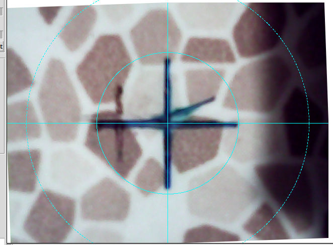
Having the camera alignment remain exactly spot on came as a pleasant surprise:
Camera Alignment check
The faded cross to the left came from the table’s previous position; there’s no positive index between the countertop slab and the underlying T-slots.
Part of the motivation for these blocks was to verify PrusaSlicer automagically handles filament / color changes between two objects, as long as OpenSCAD hasn’t unioned them as part of a common transformation. Not having to cut out the socket around the text simplifies the code from what I’d been doing with previous objects.
This file contains hidden or bidirectional Unicode text that may be interpreted or compiled differently than what appears below. To review, open the file in an editor that reveals hidden Unicode characters.
Learn more about bidirectional Unicode characters
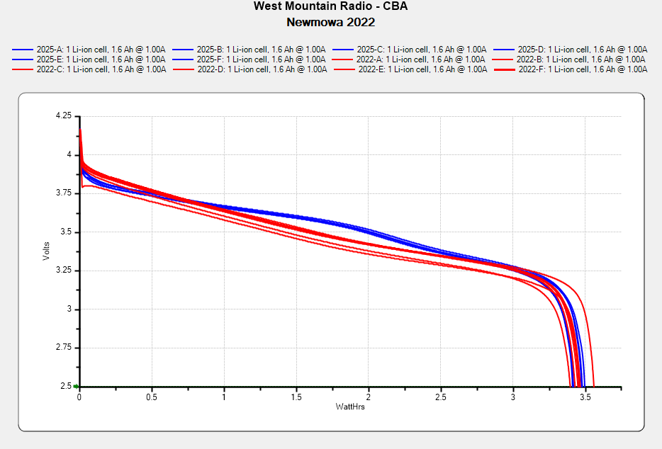
I don’t know what the bump in the middle of the new battery discharge curve means. Something weird in the chemistry, I suppose. Getting good batteries from Amazon surely remains a crapshoot and I now have four chargers.
Recharging all six batteries required 5488 mA·hr, just over 900 mA·hr apiece. Running the camera on a one-hour bike ride burns 600-ish mA·hr, so that’s comforting.
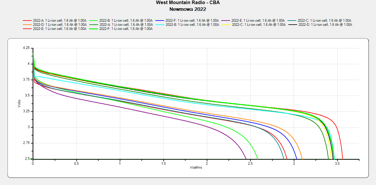
Comparing the new results with the 2022 batteries tested last month:
NP-BX1 – Newmowa 2022 in 2025-06
The upper traces appear in red in the first plot, the lower curves come from three years of use.
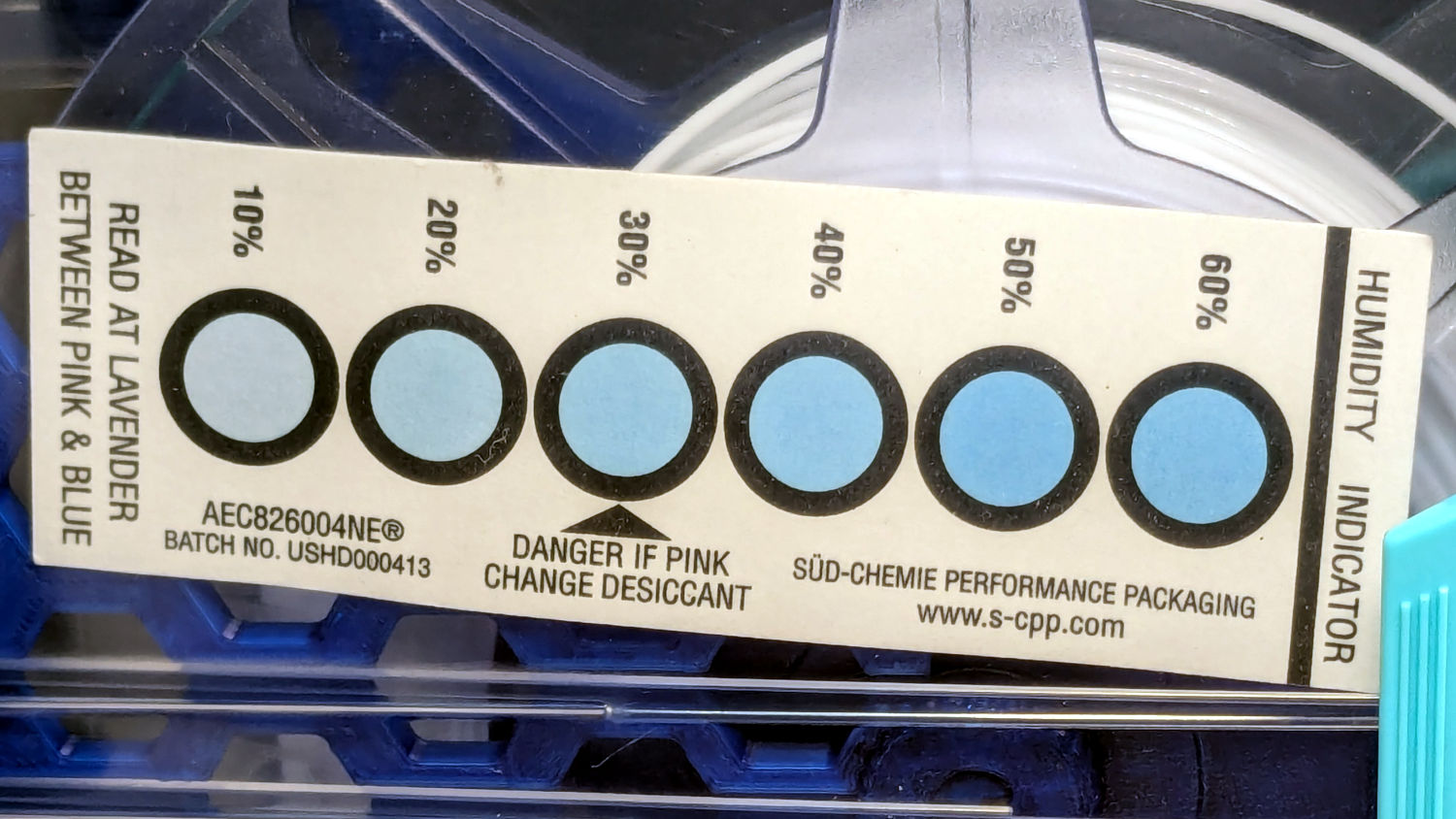
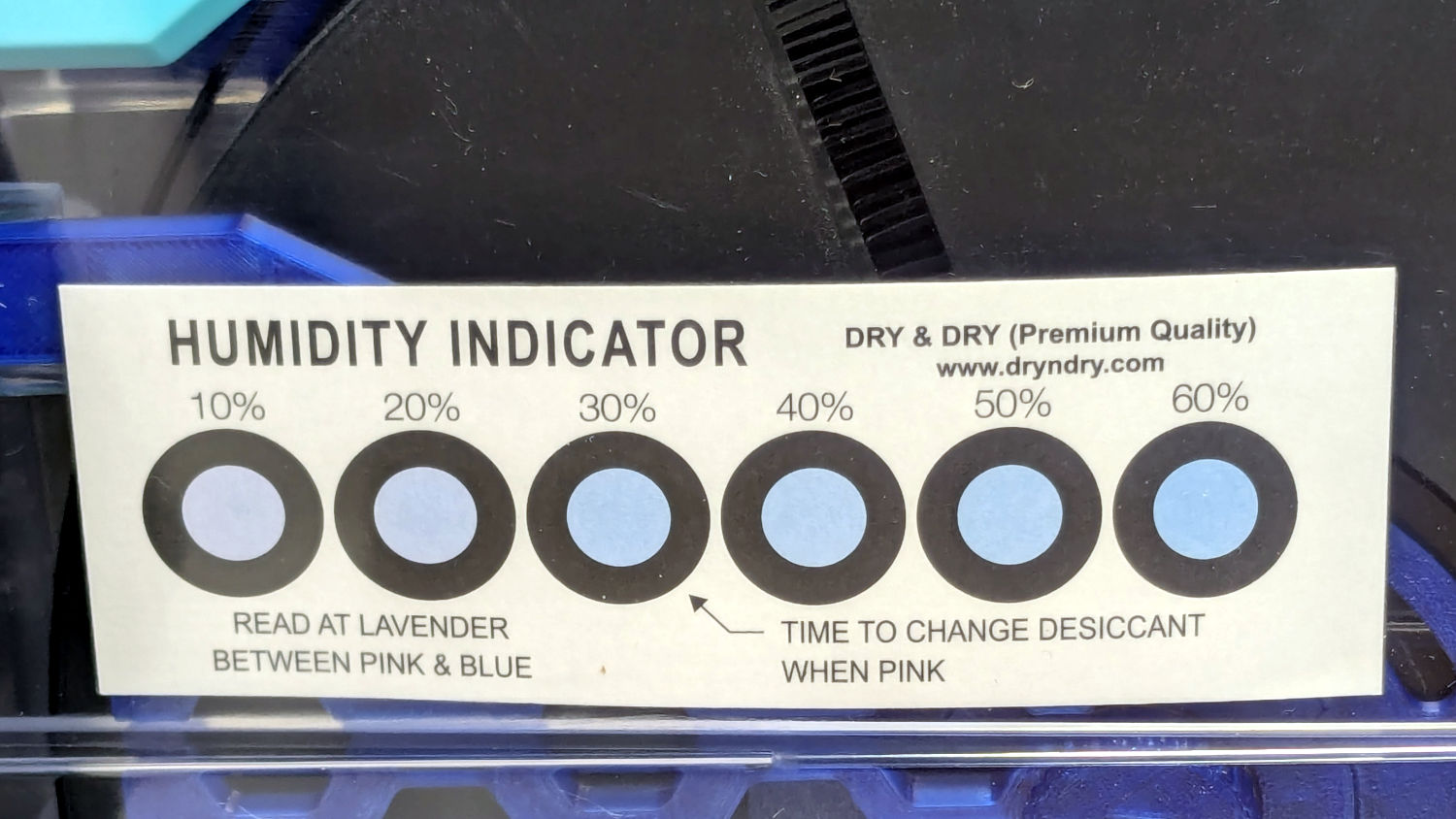
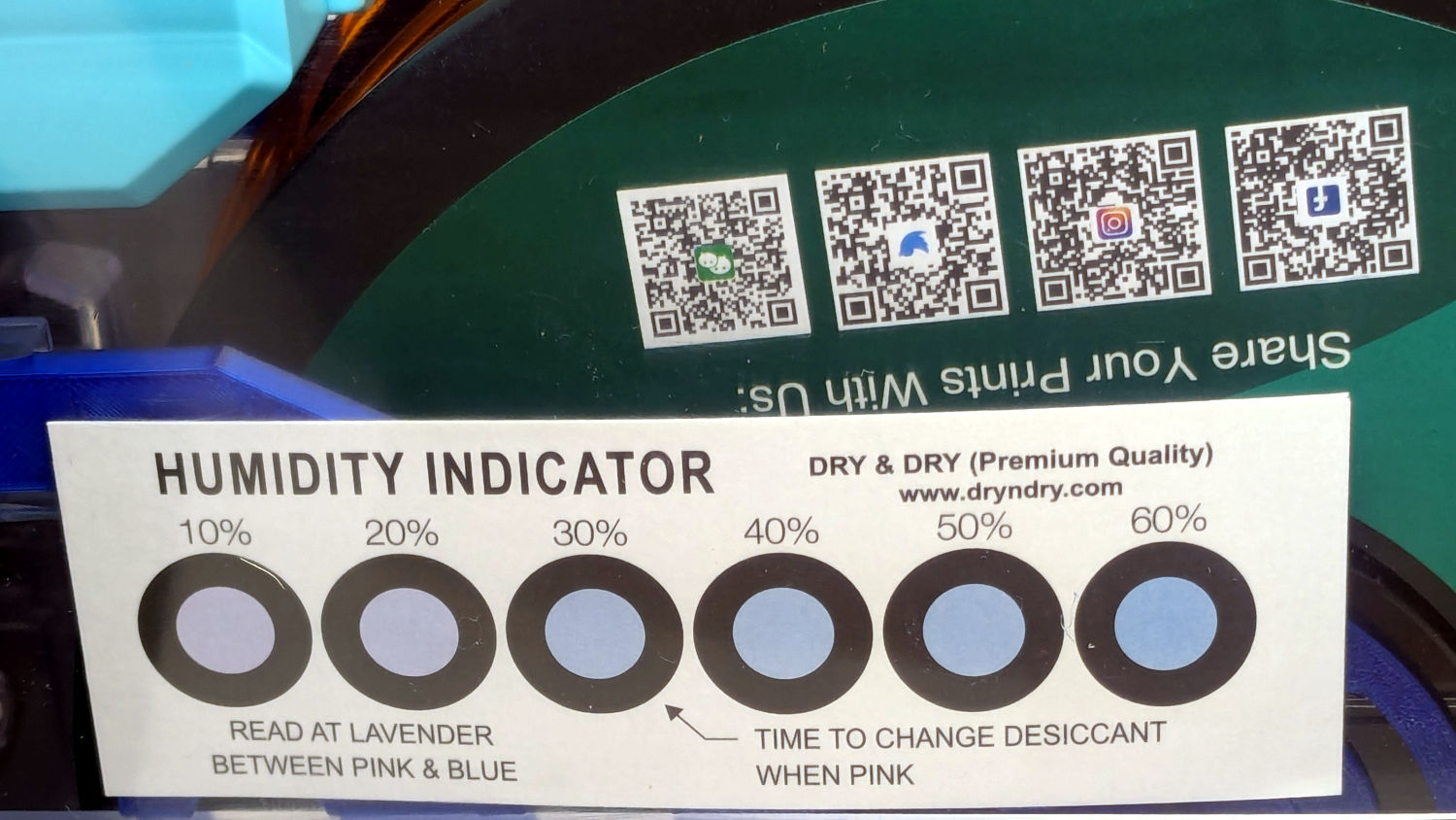
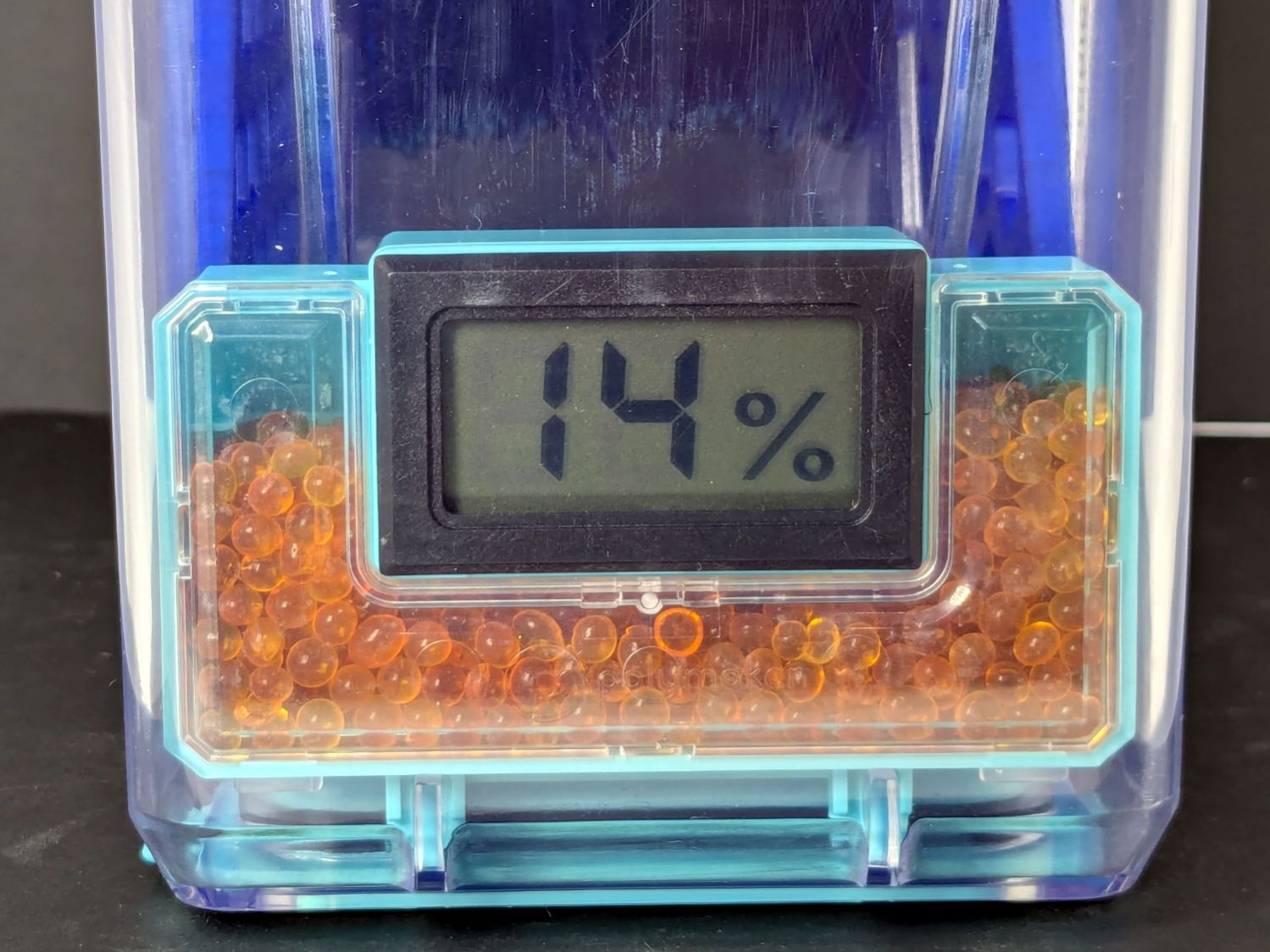
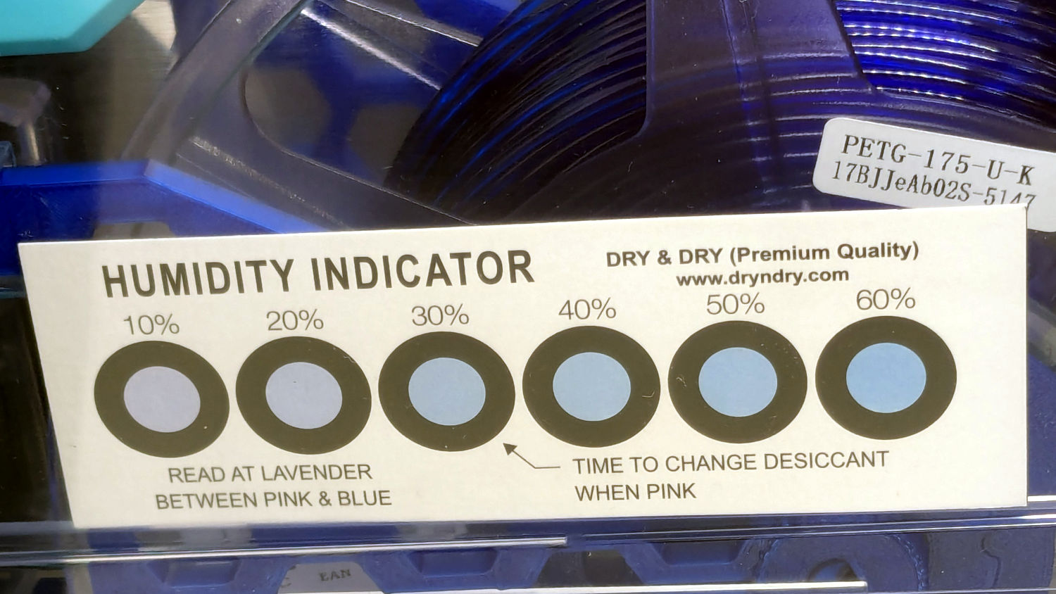
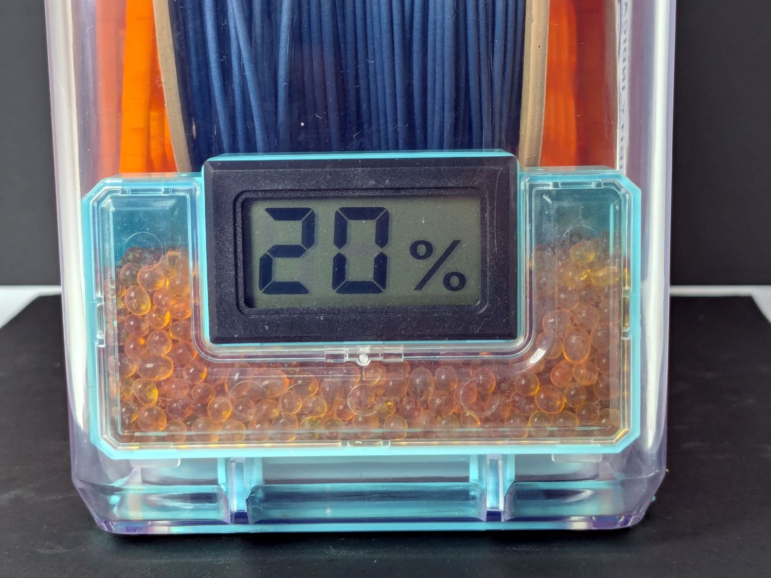
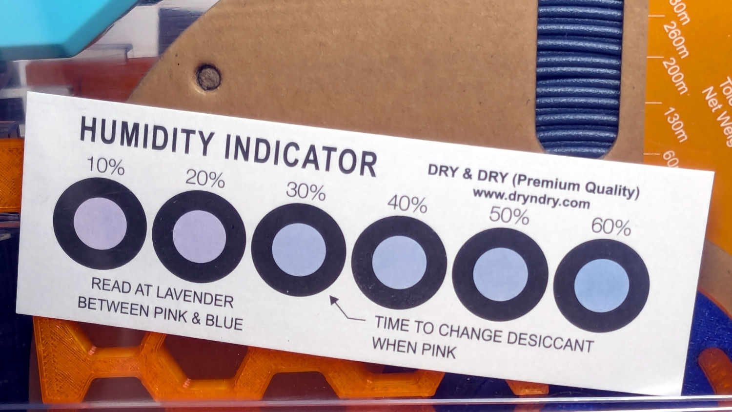
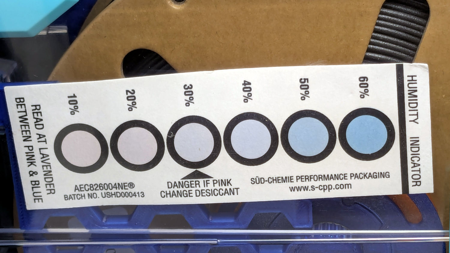
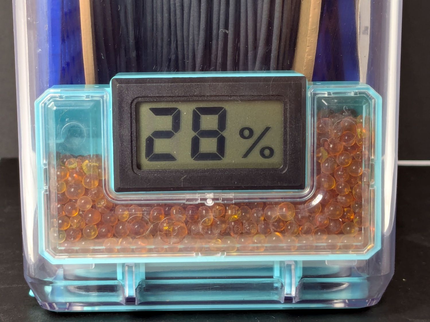
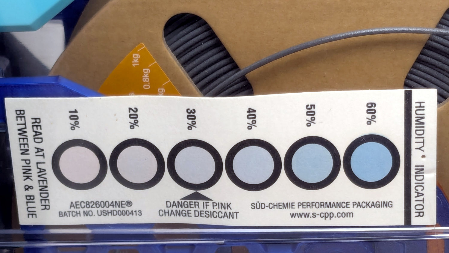
A week after installing 25 g of fresh silica gel, without any outside influence other than using some of the filaments to build things, I recorded the humidity meter reading, the indicator card colors, and the weight gain.
Click on any picture for more dots and to get rid of the captions and their stylin’ photo-blur.
White PETG, gain 0.6 g:
Polydryer – 14 pctRH – meter – white PETGPolydryer – 14 pctRH – card – white PETG
Black PETG, gain 0.8 g:
Polydryer – 21 pctRH – meter – black PETGPolydryer – 21 pctRH – card – black PETG
The (newer) indicator cards with the smaller dots / larger black borders seem less acute than the (older) large-dot cards. The two 28 %RH cards look about right, but the 20 and 21 %RH cards seem more different than the similar humidity would suggest.
Under 20 %RH, all the spots look pretty much the same, but AFAICT any humidity below 20 %RH is Good Enough for 3D printing.
The Blue PETG-CF went directly from its sealed bag into the PolyDryer box, unlike the Black and Gray PETG-CF spools that sat in the 50% RH basement long enough to soak up the ambience. The Blue has outgassed enough water to suggest spools do not arrive “bone dry” from the factory, although the Black and Gray prove the Basement Shop is wetter than the factory.
All of the silica gel together weighed 184.2 on the same scale I originally measured the 25 g quantities that should have totalled 175 g, but the individual measurements total 183.3 g. I don’t trust the scale to be better than ±0.1 g on any measurement, so half a percent is likely as good as it gets.
The silica gel weighed 187 g on the kitchen scale, sweated down to 179 g after 7 minutes in the microwave being defrosted like 1.5 pounds of fish, and, depending on which numbers you believe, released 8 to 10 g of water in the process.
Microwaving something containing so little water means the silica gel absorbs very little of the energy: the dish, glass turntable, and metal walls got absurdly hot. I think using the induction cooktop and cast iron pan makes more sense, even if it takes longer.
With fresh silica gel in place, perhaps waiting two weeks will produce interesting numbers.