Ed Nisley's Blog: Shop notes, electronics, firmware, machinery, 3D printing, laser cuttery, and curiosities. Contents: 100% human thinking, 0% AI slop.
Tag: Improvements
Making the world a better place, one piece at a time
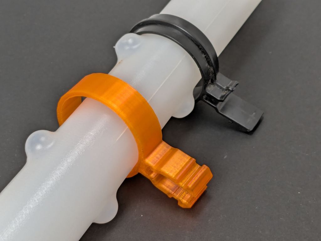
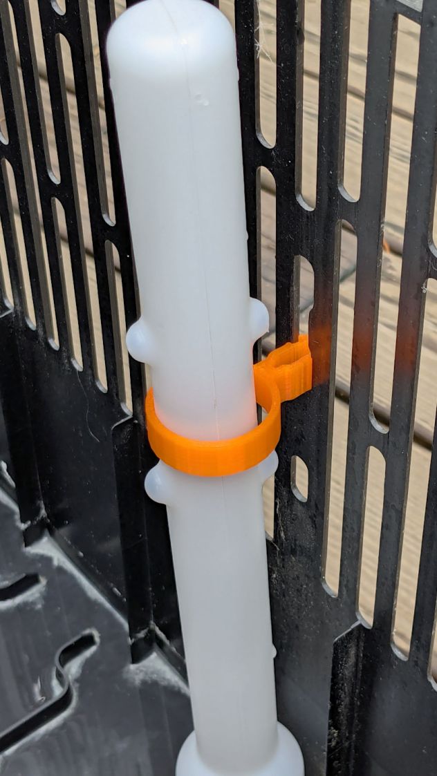
This being the end of the humidifcation season, I tried to set the longsuffering Sears Humidifier’s water level float to dry the thing out. After a few days, it became obvious that wasn’t working and I eventually found the clip intended to hold the float at the top of its travel had broken:
Humidifier float clips – on float
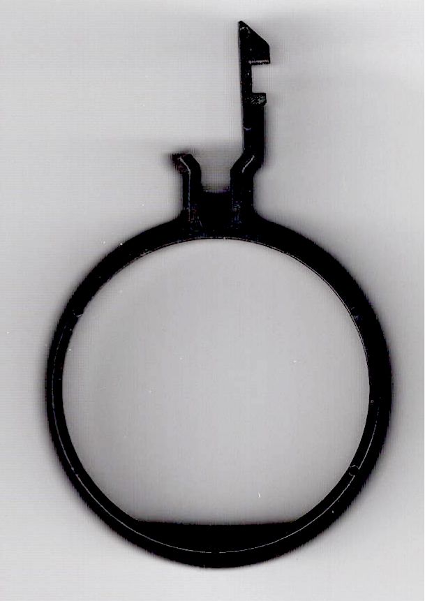
Building the retina-burn orange replacement started with a scan of the original:
Humidifier float clip
The black segment at the bottom is a shadow due to the scanner’s light bar being offset from the imaging sensor.
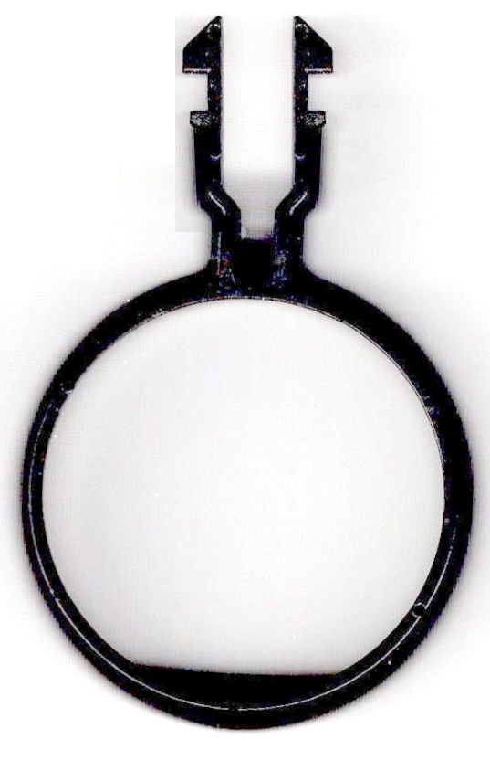
Using GIMP, duplicate the remaining part of the latch, flip it left-to-right, then align it at the proper position:
Humidifier float clip – repaired
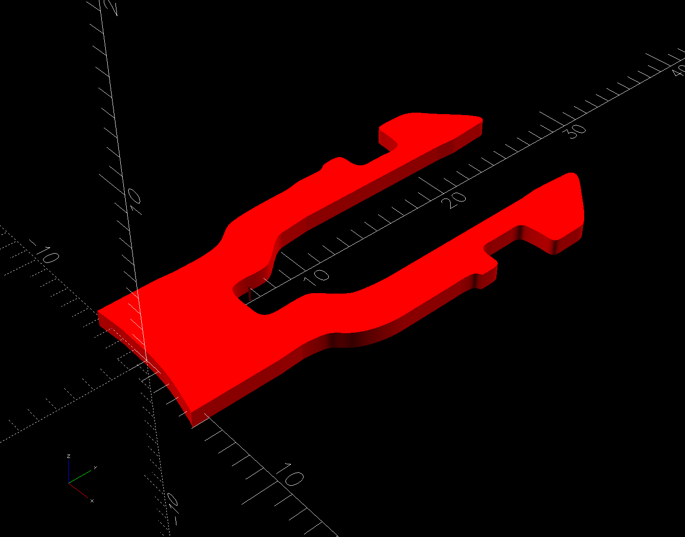
The latch is the only tricky part and the ID of the ring is easy to locate, so (still in GIMP):
Trace the edge of the whole shape
Using Quick Mask mode, remove all but the latch
Convert the selection to a path
Export it as an SVG file
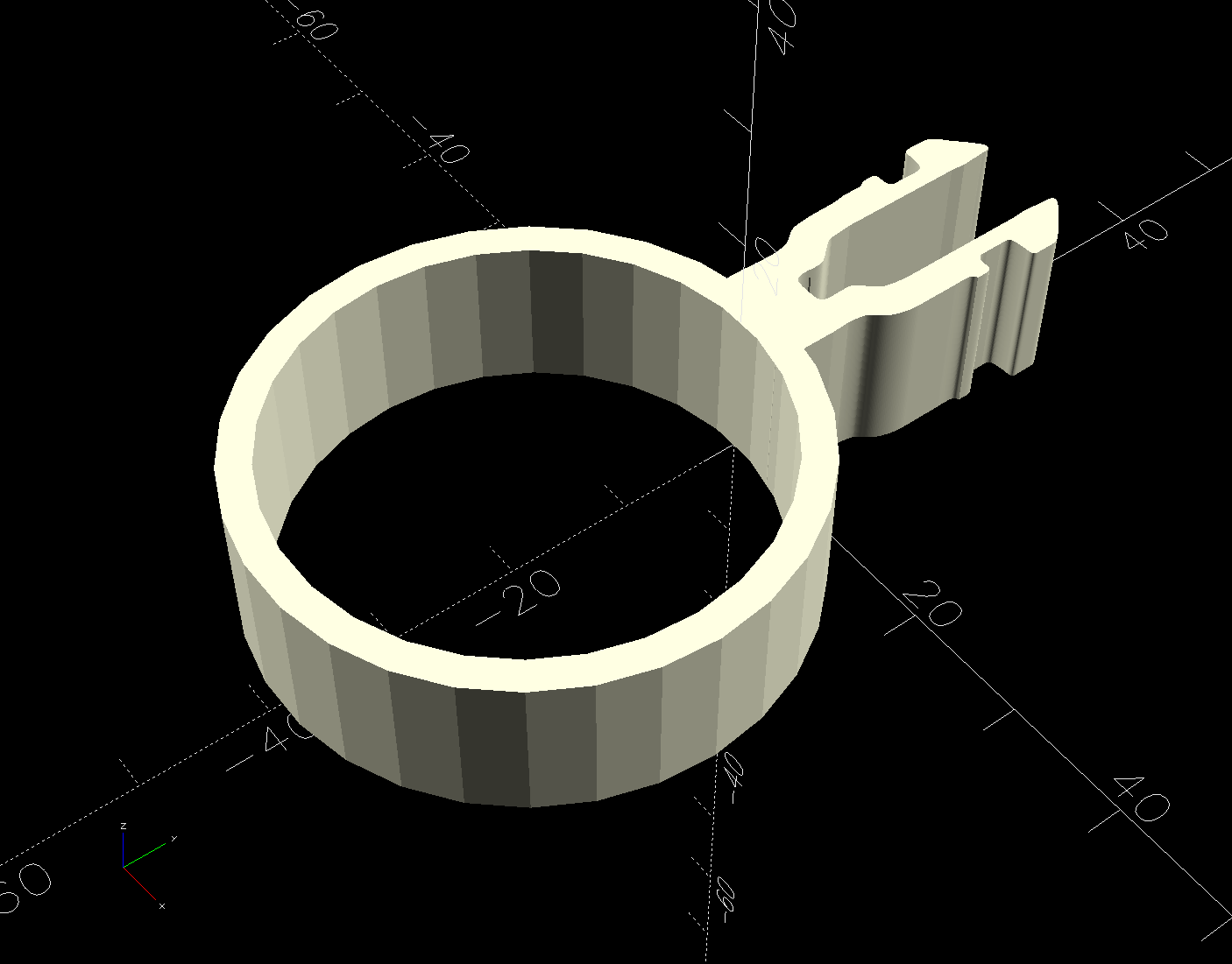
Then import it into OpenSCAD and eyeballometrically translate the shape to put the ring ID at the origin:
There being no obvious affordance to get the ring over the two bumps in the float, I applied Channellock pliers to the float while easing the ring into place.
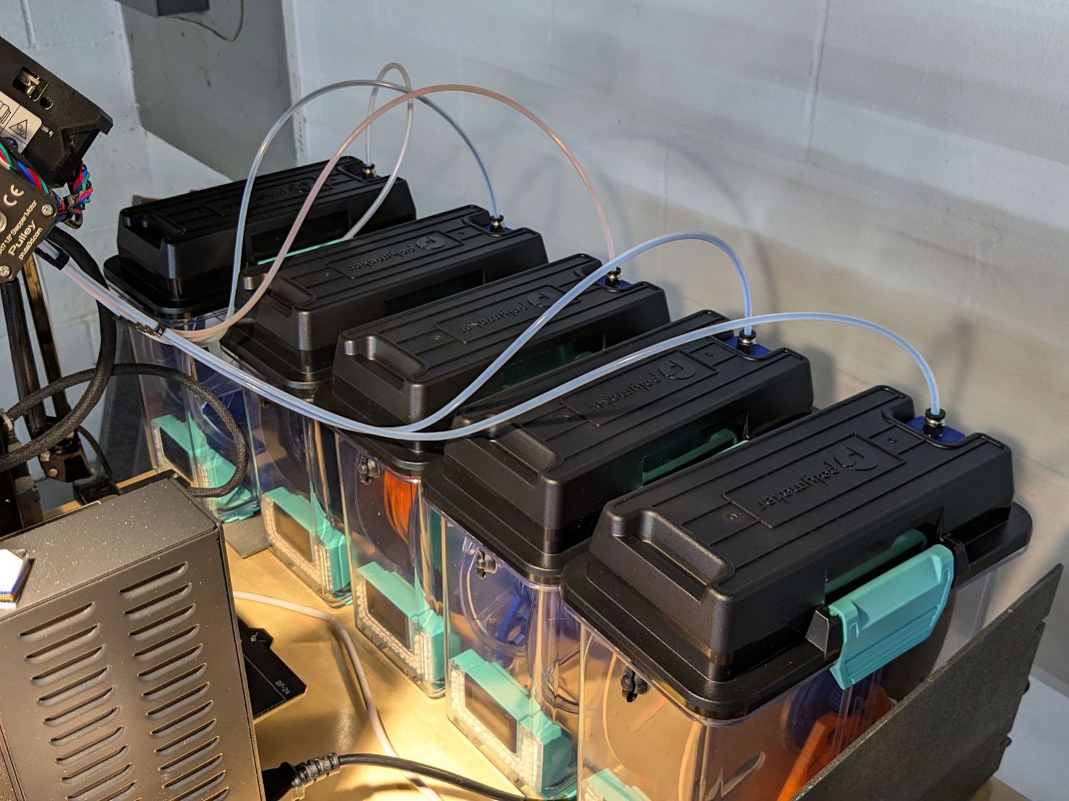
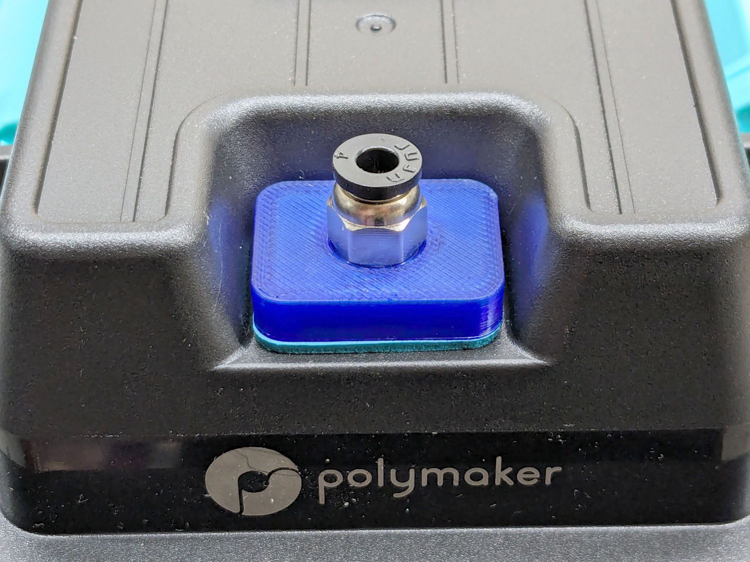
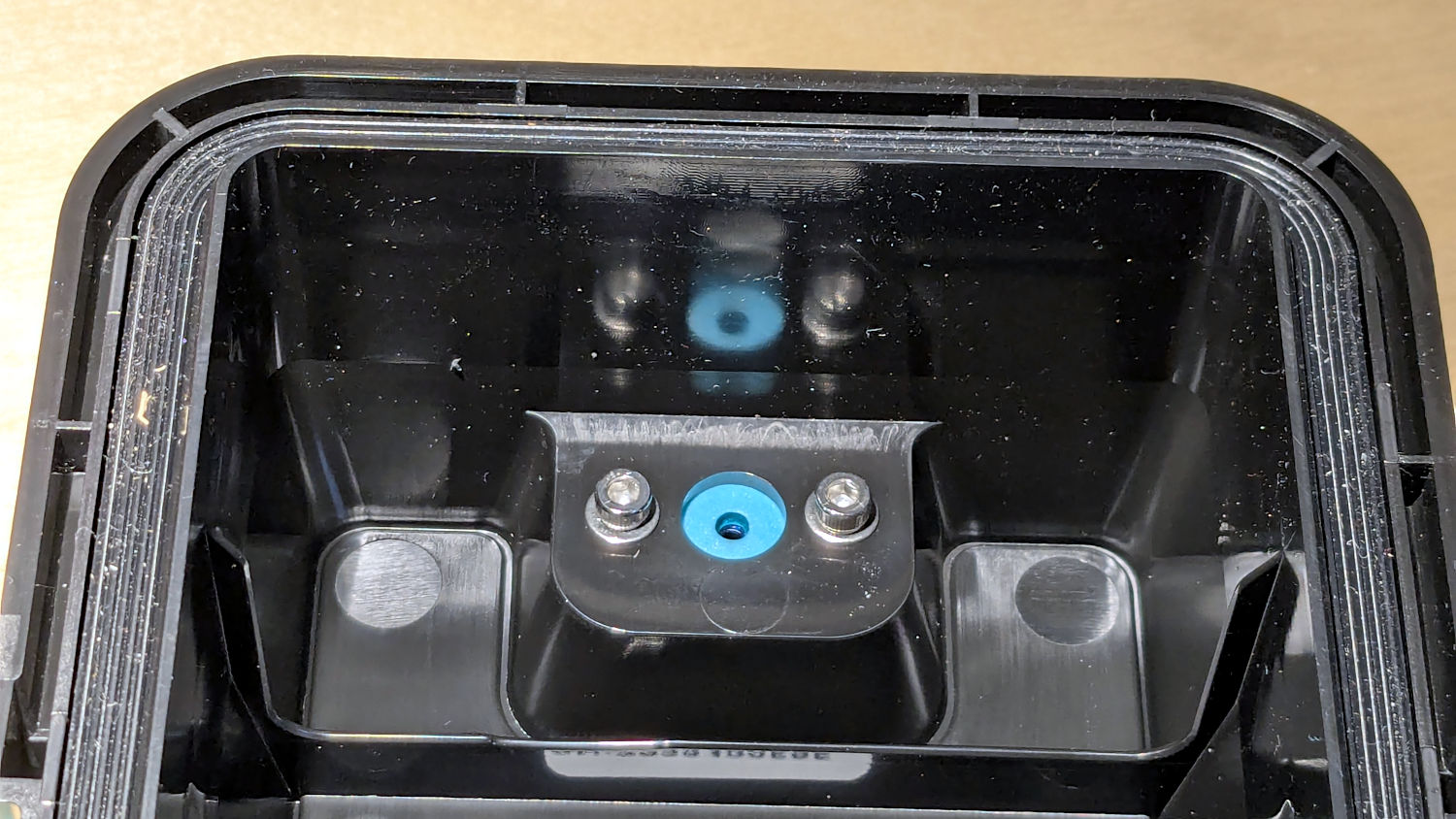
Their rubbery port covers work best with 6 mm OD PTFE tubes, but let the MMU3’s 4 mm tubes slide into / out of the boxes under normal filament extrusion / retraction forces, so I conjured an adapter for PC4-M10 pneumatic fittings:
PolyDryer PC4 Fitting – installed
A pair of M3 screws hold the adapter plate in place, with an EVA foam gasket sealing against the cover:
PolyDryer PC4 Fitting – interior view
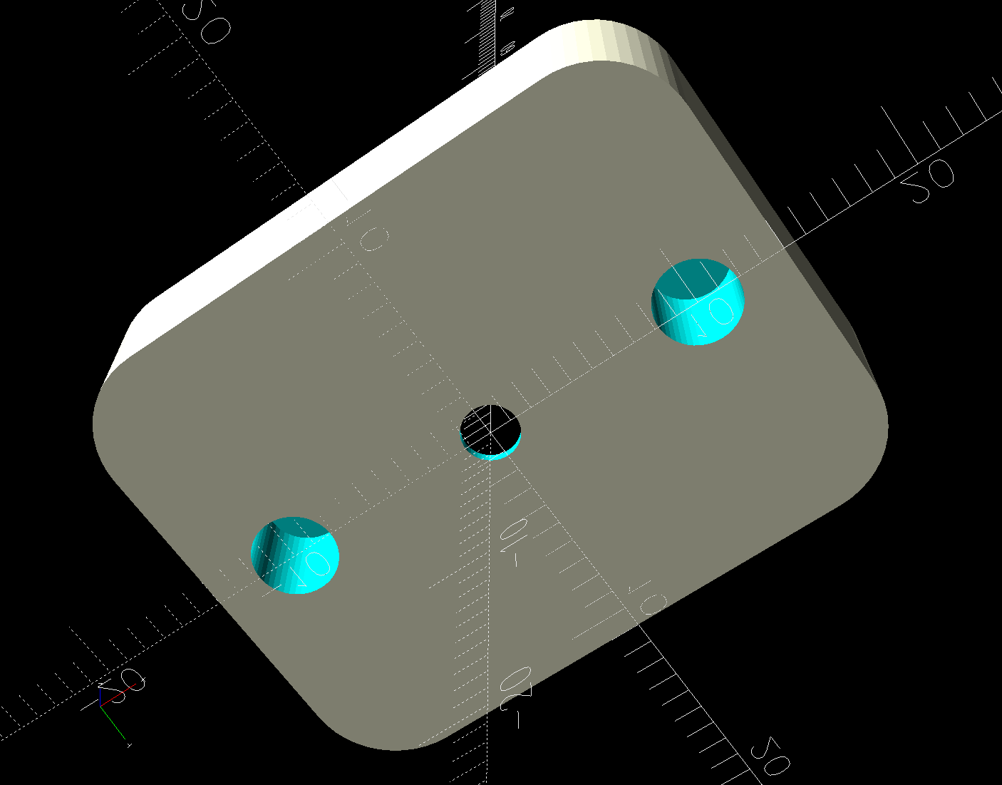
The PC4-M10 fittings let the 4 mm tubing slide right through, so the adapter has a 0.5 mm bottom sheet to block the tube, with a small hole for the filament:
PC4 Fitting Plates – bottom – solid model
You could use PC4-M6 fittings to block the tubing, but the 2 mm lumen on the fittings I have barely pass 1.75 mm nominal filament. Comments found elsewhere suggest identical PC4-M6 fittings have smaller lumens that snag the filament as it moves in one direction or the other.
The two blind holes get heat-staked 4×4mm M3 brass inserts.
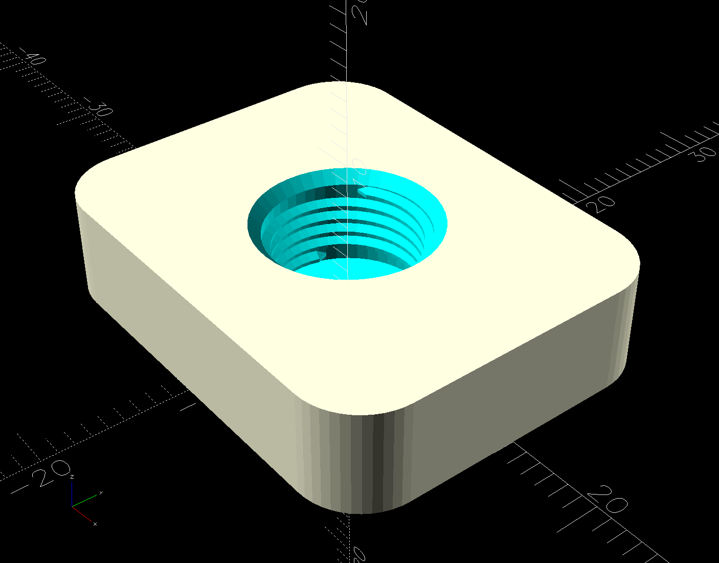
The top has a threaded hole for the fitting:
PC4 Fitting Plates – top – solid model
Despite what the description says, the thread is not an M10 metric straight thread: it is a tapered pipe thread used for gas- and liquid-tight fittings. Considerable measurement & searching suggested a ⅛BSP-28 thread, because:
British Standard Pipe threads are used everywhere in the world except the USA
Both my metric tap sets have a ⅛BSP-28 tap along with all their hard-metric straight taps
The thread is painfully close to ⅛NPT-27, which would probably work in a pinch if it was the only tap you had.
Those PC4-M6 fittings might sport 1/16BSP-28 threads, but you’re on your own.
Further searching suggests nobody uses the corresponding tapered female pipe threads and everybody goes with a straight internal thread, so I conjured a stumpy threaded rod using the BOSL2 library and removed it from the adapter plate:
The 9.7 mm diameter is the ⅛BSP-28 “major diameter”, rather than its “gauge diameter”, simply because it produced a good fit. The beveled top guides the fitting into the hole, but I still managed to cross-thread one.
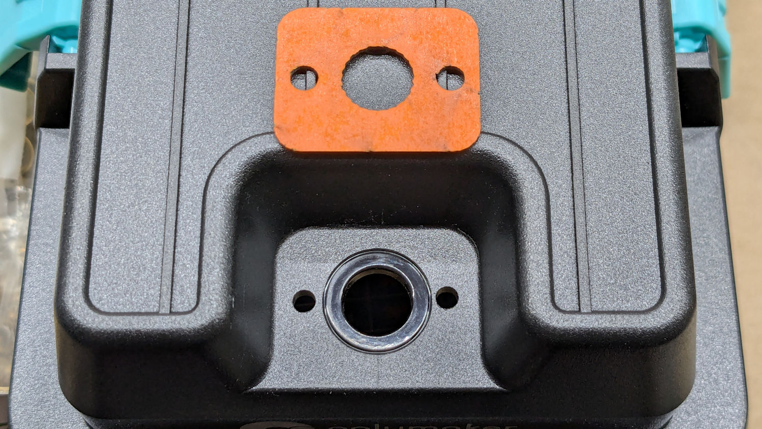
The OpenSCAD code also produces SVG files to laser-cut the foam gasket and a drill template:
PolyDryer PC4 Fitting – drill template
The holes were step-drilled to ⅛ inch (which has a historic relation to the ⅛BSP-28 size, because iron pipe) for a generous fit around the M3 screws.
That was way more complicated than I expected and I’m really glad to live in the future where this is a 3D printer project, not a metalworking project involving an actual tap in, say, steel.
This file contains hidden or bidirectional Unicode text that may be interpreted or compiled differently than what appears below. To review, open the file in an editor that reveals hidden Unicode characters.
Learn more about bidirectional Unicode characters
After about 7.5 years (!) the 64 GB card in my Sony HDR-AS30V helmet camera breathed its last:
SanDisk 64 GB MicroSD card – end of life
Over the course of several rides I noticed many video files ended prematurely or would not play. I gave up attempting to reformat the card in overwrite mode using the Official SD Card formatter after four hours, which says the wear leveler in the card has no spare capacity.
In round numbers, I ride 1700 miles a year at 12 mph, so the card recorded 1000 hours of 1920×1080 video at 60 frame/s, storing one 4.3 GB file every 22.75 minutes for a grand total of 12 TB of data.
A new Sandisk 128 GB High Endurance card cost a third of what the 64 GB card did and, after setting the partition label to AS30V, it’s off to a good start:
Street Lamp Pole – Rombout House Ln – 2025-05-07
That’s the street lamp pole installed on the replaced base at the corner of Rt 376 and Rombout House Lane, with the barrels gradually being pushed closer and closer to the pole by turning traffic on the newly paved lane.
That pole is not going to see the end of this year.
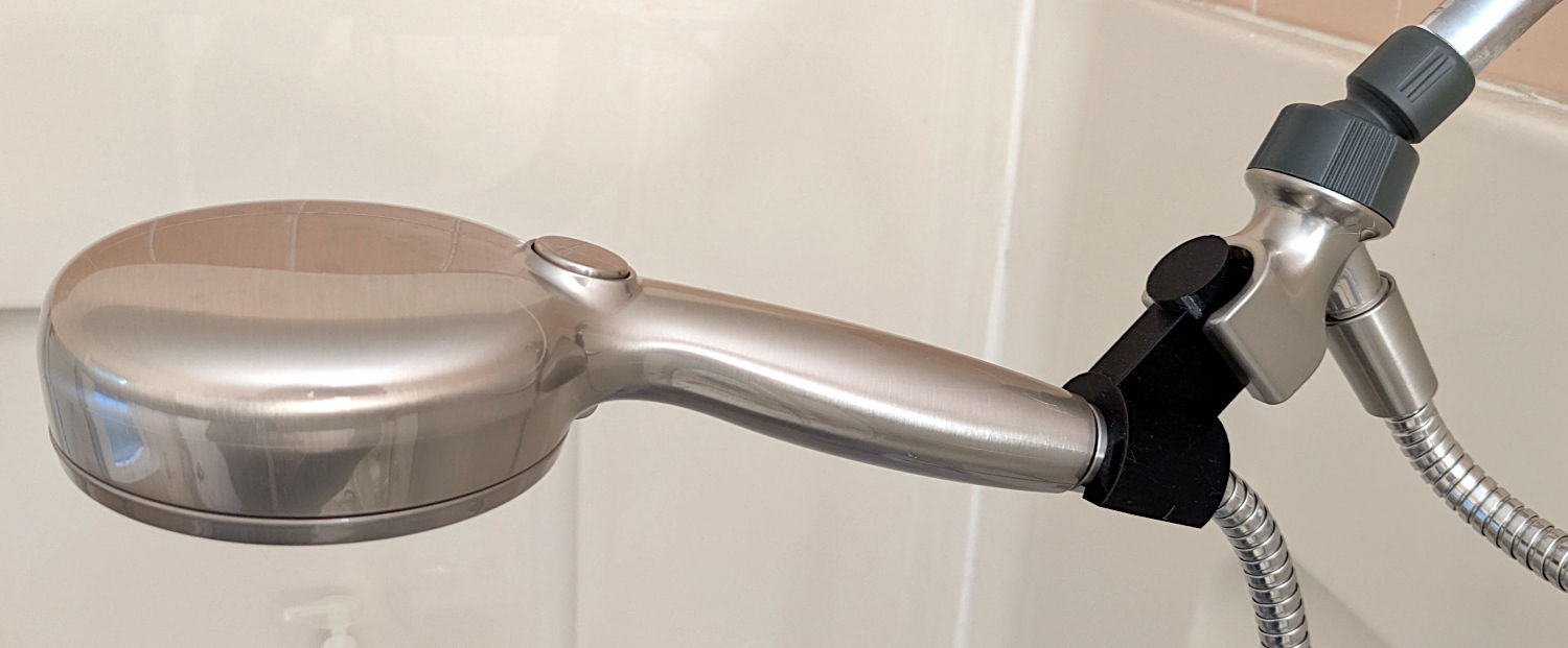
The original shower head being too far overhead for Mary’s reach, I installed a Delta ProClean Shower Head which would also be too high. It has a hose, which means I can adjust the height:
Delta shower head holder extension – installed
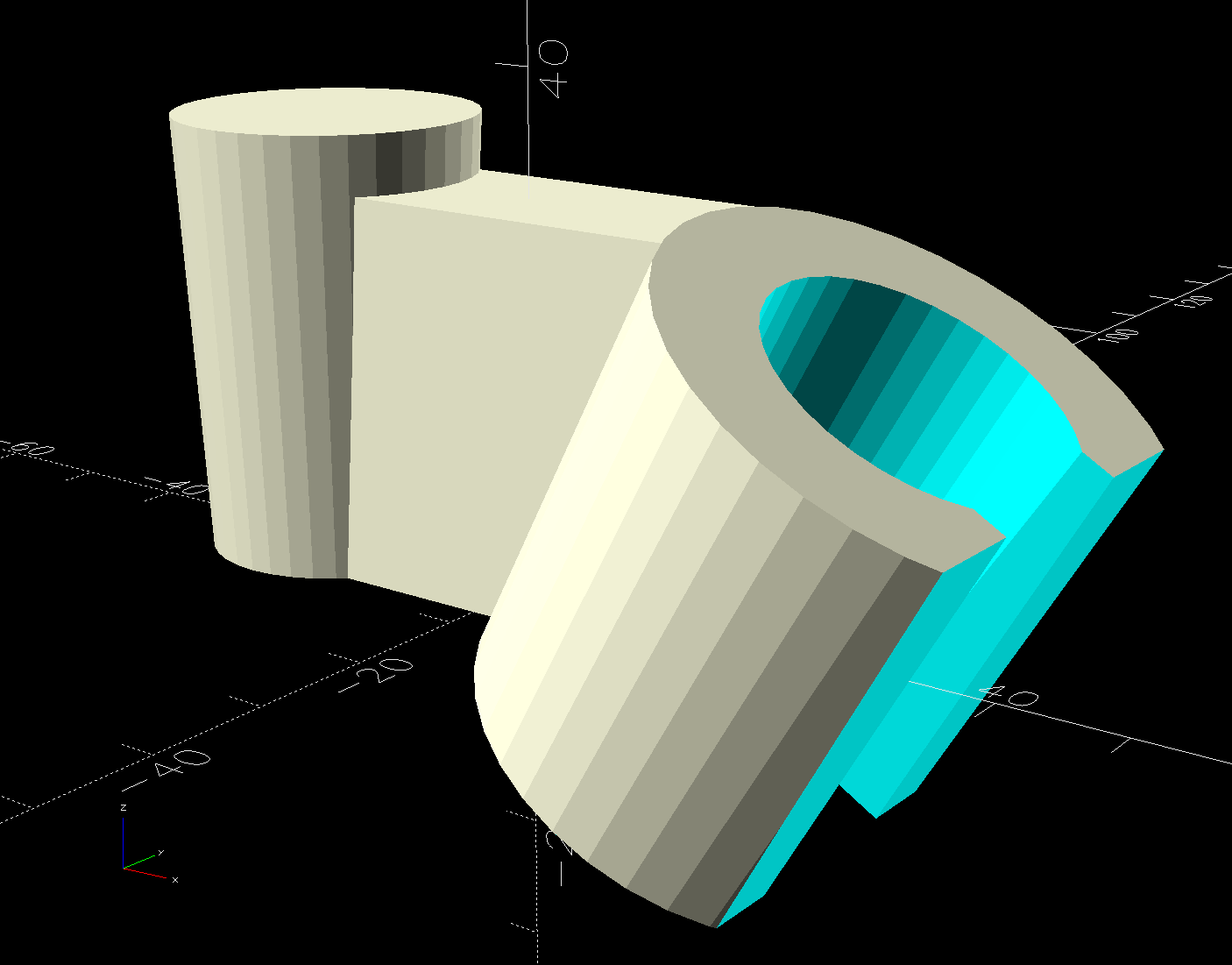
The InterWebs offer several 3D-printable versions of such a thing, but Delta offers many different shower heads, some of which are visually (to my eyes, anyway) indistinguishable from the 75740SN you see here. The model I tried did not fit the holder I have, so I conjured one from the vasty digital deep:
Delta shower head holder extension – solid model
It builds standing on that tidy cutoff:
Delta shower head holder extension – PrusaSlicer warning
Despite PrusaSlicer’s kvetching about the “collapsing overhang” inside the socket, it came out fine.
The shower head is still slightly too high for her, but now I can print another one with a longer offset and a slightly smaller plug to fit deeper in the OEM socket.
Worst case, there’s a wall-mounted holder to put the shower head at shoulder height.
This file contains hidden or bidirectional Unicode text that may be interpreted or compiled differently than what appears below. To review, open the file in an editor that reveals hidden Unicode characters.
Learn more about bidirectional Unicode characters
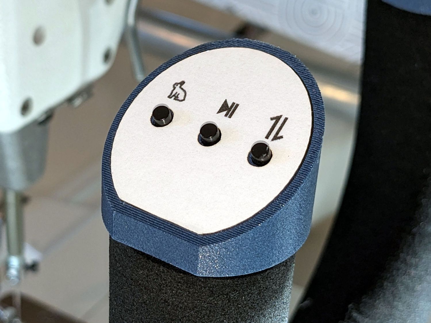
The new control caps on the HQ Sixteen’s handlebars have three switches apiece:
HQ Sixteen – grip cap installed – left
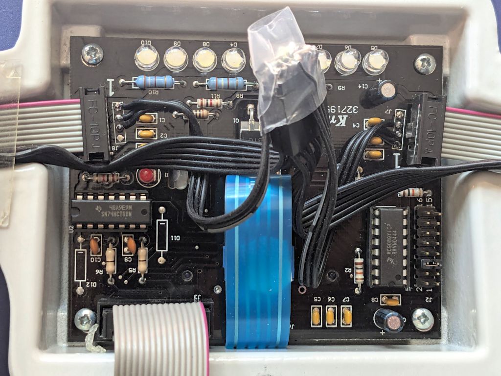
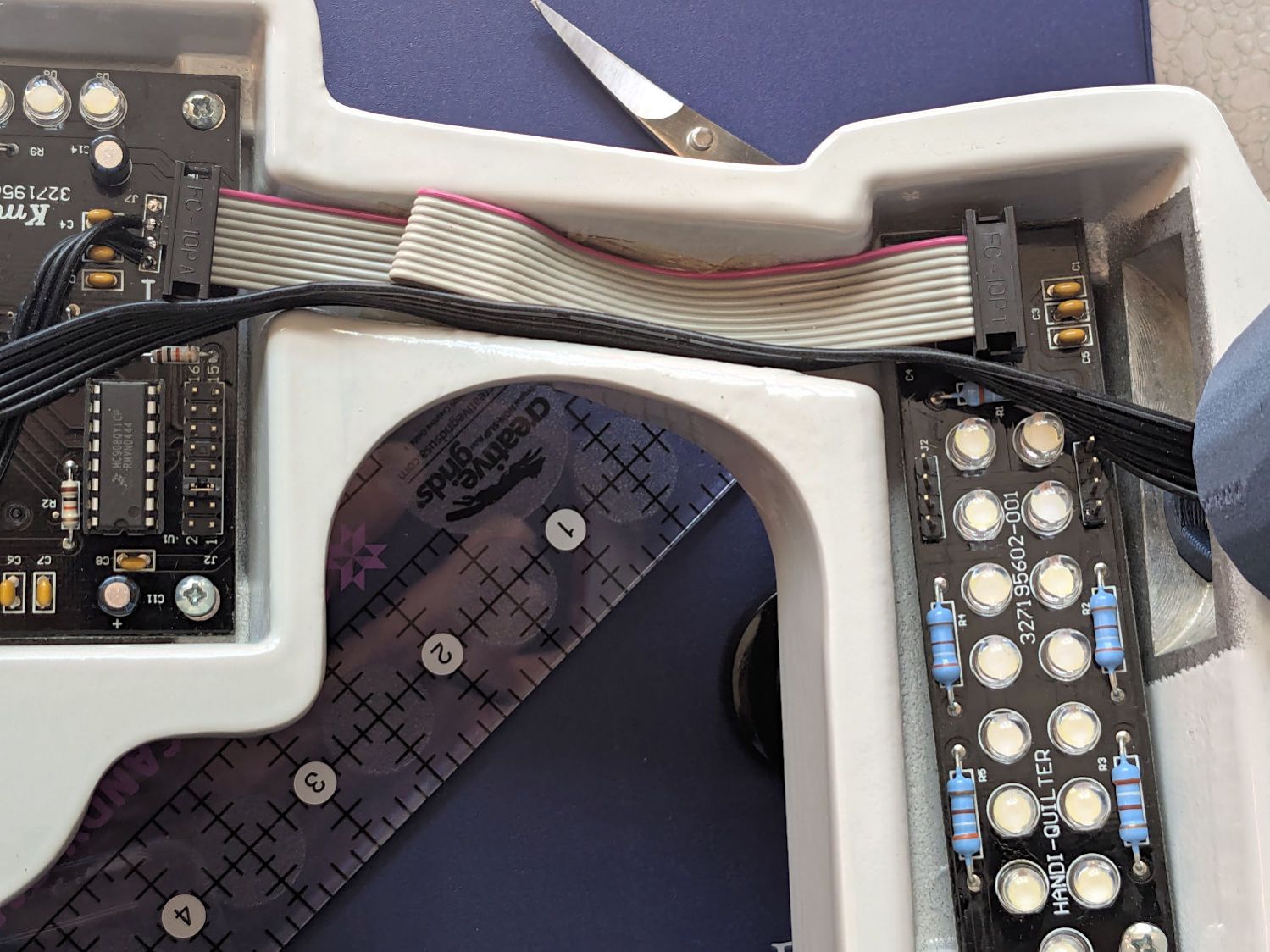
A six-conductor ribbon cable brings those switch terminal through the handlebars, across the smaller PCBs where the original switches plugged in, and atop the main PCB behind / under the LCD panel where they get wired together:
HQ Sixteen – Control Button switch cable
The gray ribbon cable carries power for the LEDs and returns the original switch signals formerly plugged into one of the four-pin headers on the right PCB. The same PCB is used on the other side and the switches over there plug into the other header.
The central PCB is also used for the rear handlebars, which do not have the smaller PCBs, and those switch cables plug directly into four-pin headers mounted instead of the headers for the gray ribbon cables:
HQ Sixteen – Control Button central PCB
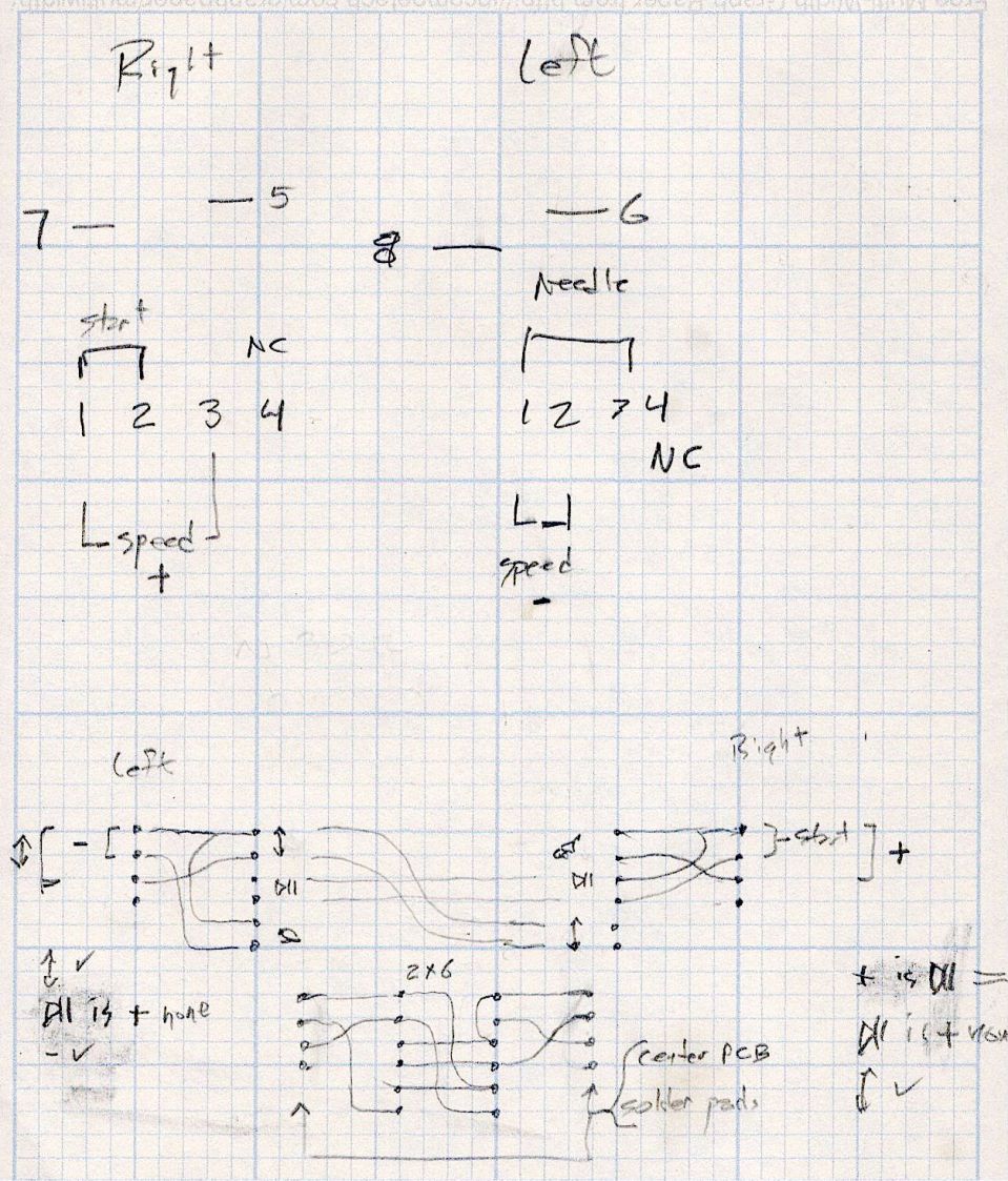
Some probing and doodling produced a diagram of the switch connections:
HQ Sixteen – Control Button Wiring
Working with the handlebars either inverted or flipped left-for-right on the workbench makes this far more confusing than it really should be.
In any event, the bottom diagram shows the connections between the two four-pad header positions on the central PCB and the two six-pin headers for the new switches. I used a 2×6 pin header block to plug in the new switches, connected the pins with soldered Wire-Wrap wire, and used three-wire ribbon cable to the PCB pads.
The general idea was to duplicate the Start-Stop and Needle Up/Down switches on both sides, while maintaining the same relative positions of the Fast / Slow switches. In effect, the two new switches on each side are wired in parallel to the original switch pads on the PCB.
Surprisingly, I got the three-wire ribbon cables from the four-pad headers right on the second try, which involved flipping it over. The top and bottom pads on those headers are connected together, so the three-wire cable can go on either way to reverse the positions of the other two wires.
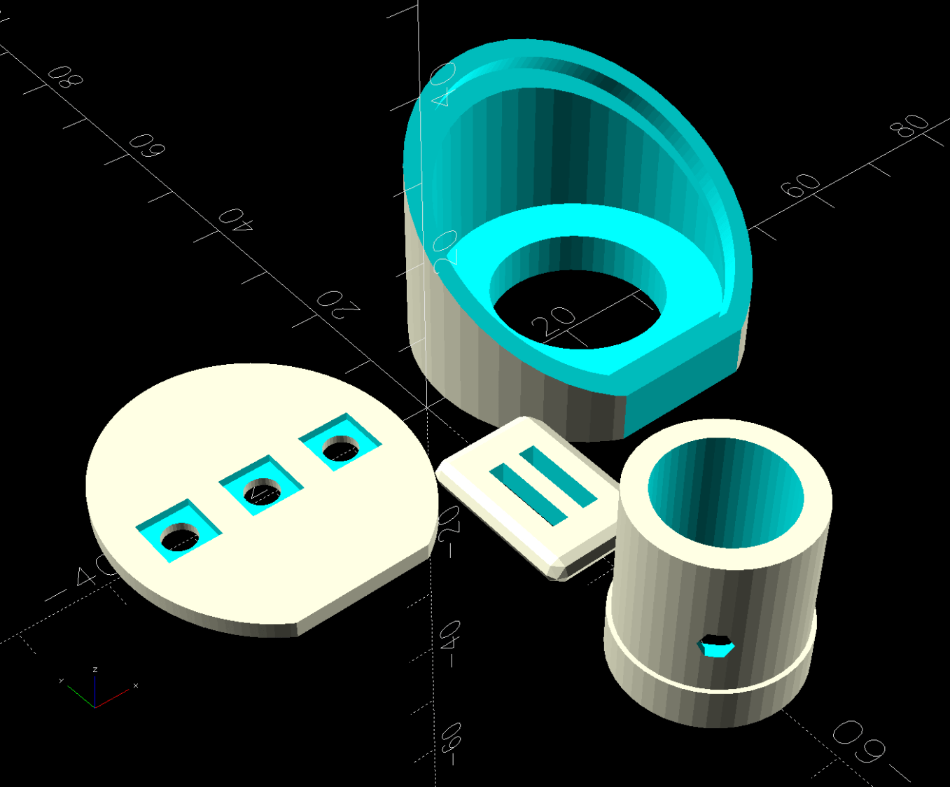
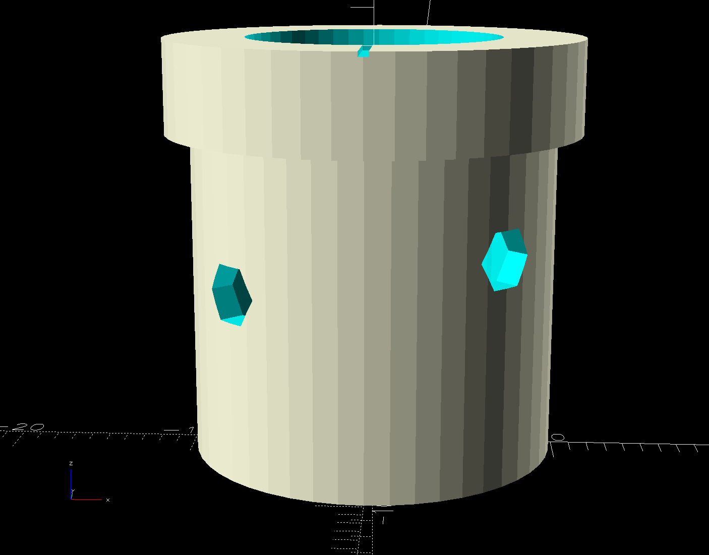
My version of the Handi-Quilter HQ Sixteen grip control caps requires some assembly:
Control Button Caps – solid model – build view
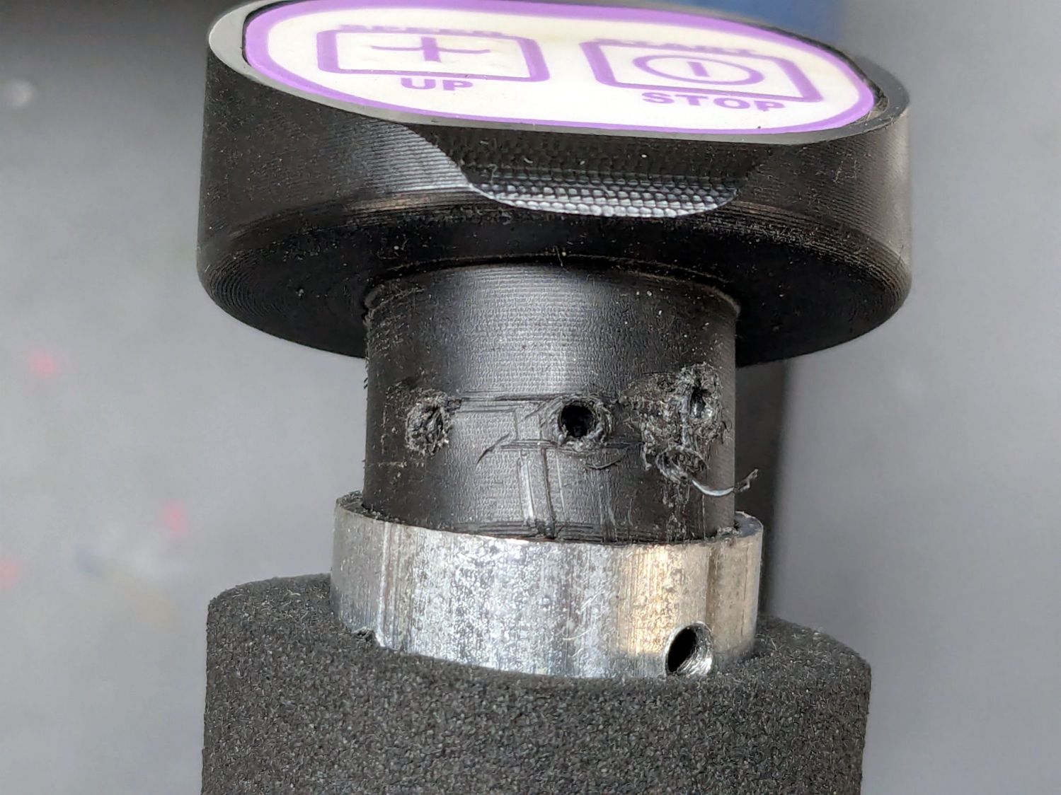
Getting the OEM caps off the handlebars required carefully applying torque through a strap wrench, but they eventually came free:
HQ Sixteen – OEM grip cap – screw holes
I don’t know what the unused screw hole between the two gnarly holes was for; perhaps they discovered one hole was inadequate.
The alert reader will note the two screw holes are not the same distance from the end of the tube, which required rebuilding the plug model to match:
Control Button Caps – solid model – plug holes
Which is why I didn’t glue the plug into the cap before I got the OEM caps off.
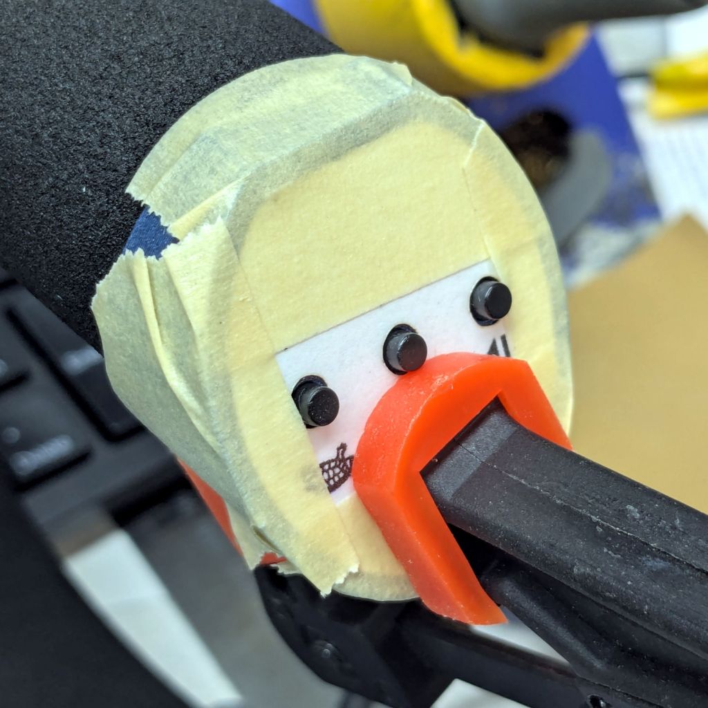
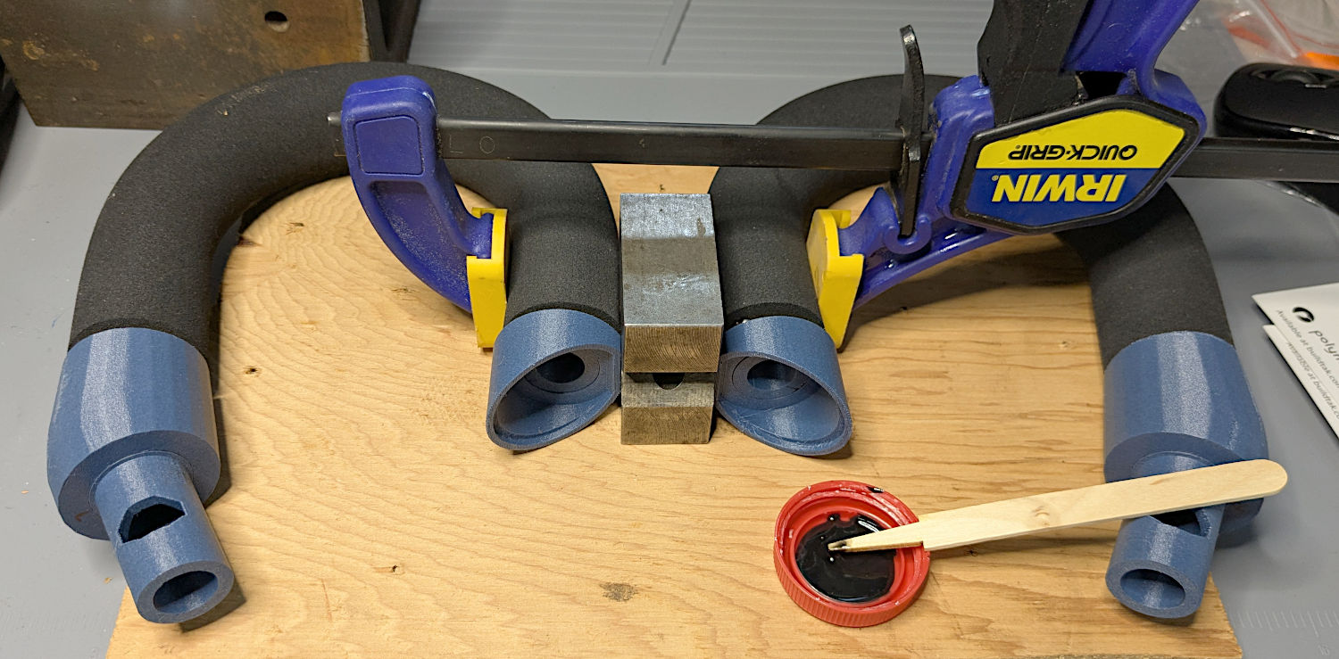
Redrill the tube holes to 3 mm, file the burrs from both the OEM and my drilling, smooth the edges, and the plug fit perfectly. Then I seated the M3 square nuts behind those hole and, after installing the new plugs in the handlebars, glued the caps in place with a simple fixture to ensure the front faced forward:
– HQ Sixteen – grip cap faceplate gluingHQ Sixteen – grip cap gluing
The clamp gently compresses the foam enough to hold the flats against the bench block while the JB Plastic Bonder cures.
After verifying all the buttons worked, I glued the faceplates to the cap bodies:
HQ Sixteen – grip cap faceplate gluing
The tape held the faceplate in place while I snugged the clamps.
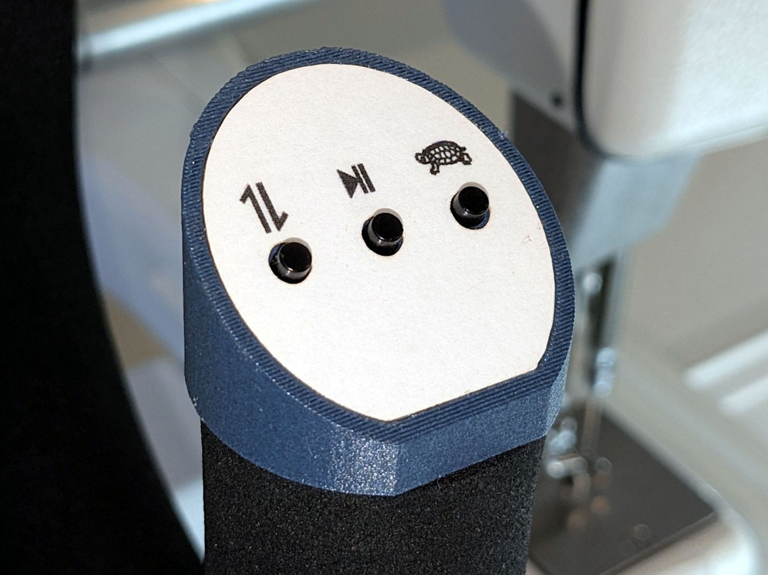
Modulo my weak graphic design skills, the caps look pretty good:
HQ Sixteen – grip cap installed – right
And, after a bit of wiring yet to be described, the buttons do exactly what their legends suggest:
HQ Sixteen – grip cap installed – left
The white sheet with feeble graphics can be peeled off, so I have another chance to tart it up.
The overall idea was to replace the failing Start/Stop switch while duplicating that switch on both caps. While I was at it, I also duplicated the Needle Up/Down button, because who wants asymmetric caps?
Mary is assembling another quilt and the new switches will get plenty of action …
Setting up the Makergear M2 to print TPU (eSun 95A) involved a cold pull to get the remaining PETG out of the nozzle, some manual flushing, then printing test cubes to figure out a reasonable speed / temperature combination:
Makergear M2 – first TPU test cube
A 10 mm solid cube came out overstuffed and the first 20 mm cube lacked enough infill to hold its top up, but the third cube looked surprisingly good at 230 °C and 30 mm/s with 15% 3D Honeycomb infill:
Makergear M2 – TPU test cubes
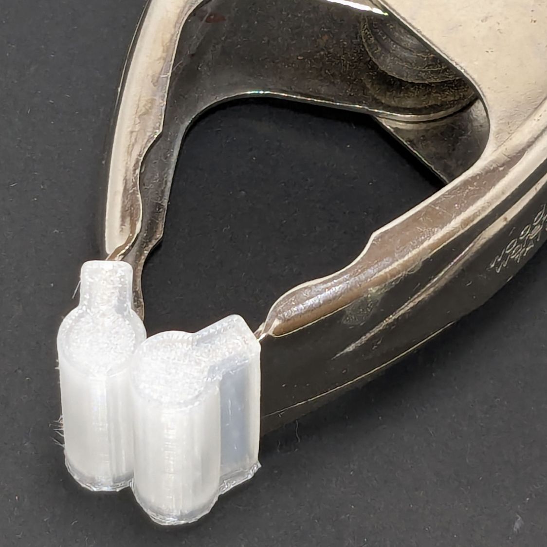
With that settled, I conjured pairs of soft (-ish) jaw pads for the far-too-many metal spring clamps having worn out their vinyl pads:
Spring clamp jaws – installed
Those were the first attempt and worked well enough to suggest nicely rounded endcaps instead of flat cylinders:
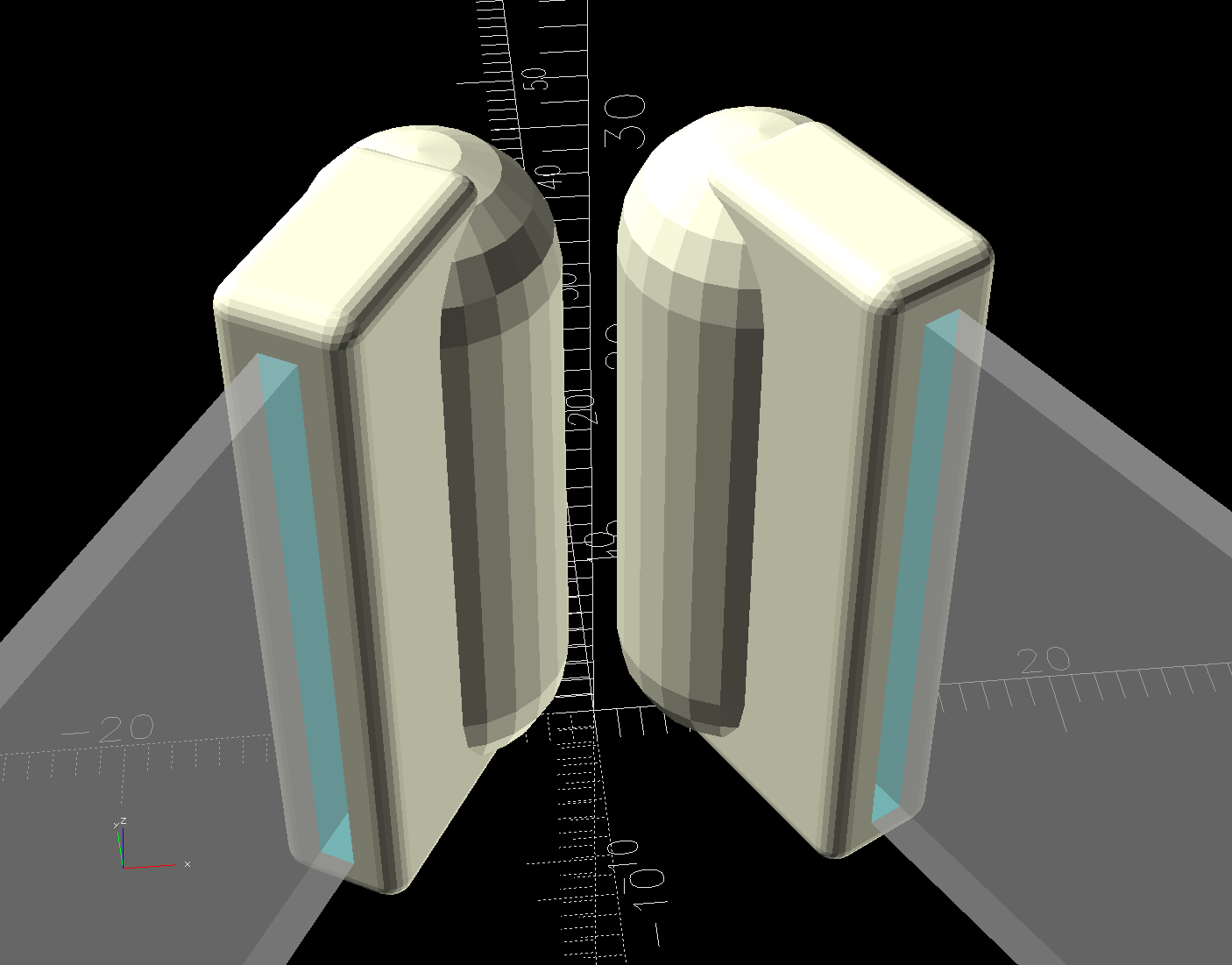
Spring Clamp Jaws – show view
Unlike the first version, they now build standing on their rectangular clamp jaw opening:
Spring Clamp Jaws – show view
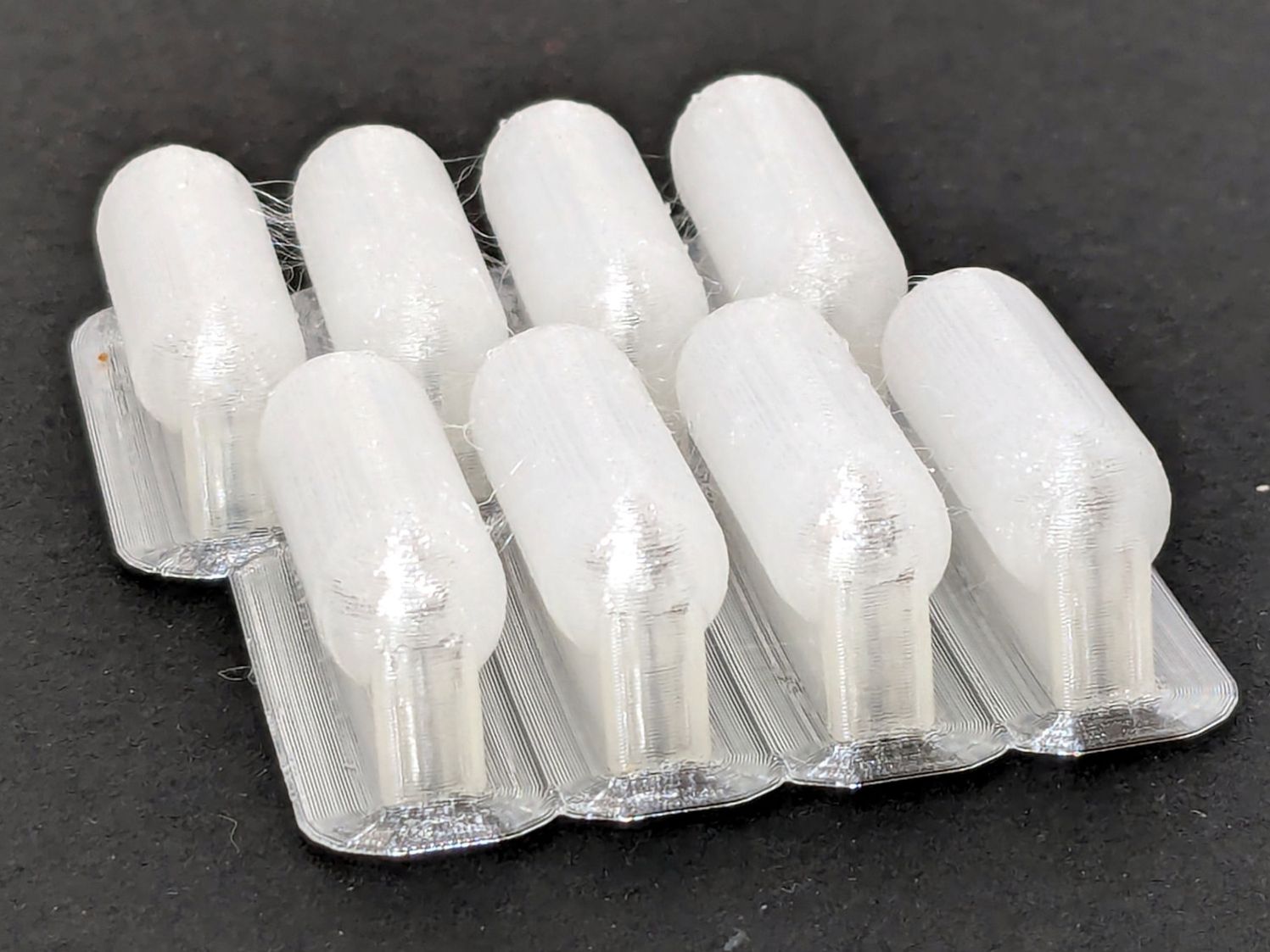
Those two groups have different lengths (1 inch and 1-⅛ inch) with PrusaSlicer combining the OpenSCAD program’s output.
The as-built pads are essentially un-photographable:
Spring clamp jaws – group build
TPU is tough enough to make the single-layer brim un-tearable, but they’re easy enough to separate & trim with scissors. Even the 5 mm brim has a tenuous grip on glass + Suave hair “spray” applied from a dropper bottle, so I should try a BuildTak sheet that’s been on the to-do pile for far too many years.
Similarly, TPU is flexy enough to make a precise fit unnecessary: push firmly to force the pads onto the jaws and you’re done.
This file contains hidden or bidirectional Unicode text that may be interpreted or compiled differently than what appears below. To review, open the file in an editor that reveals hidden Unicode characters.
Learn more about bidirectional Unicode characters