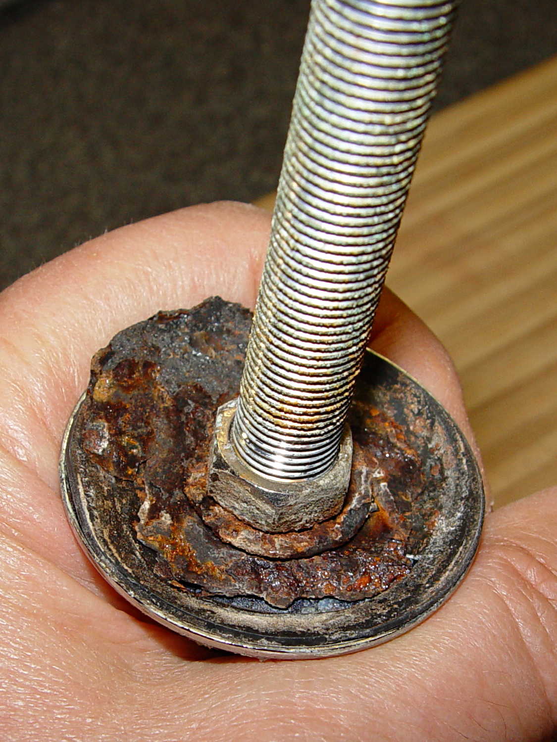
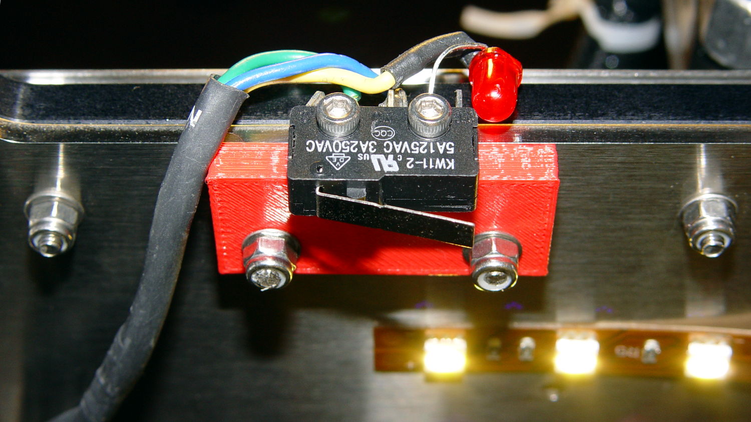
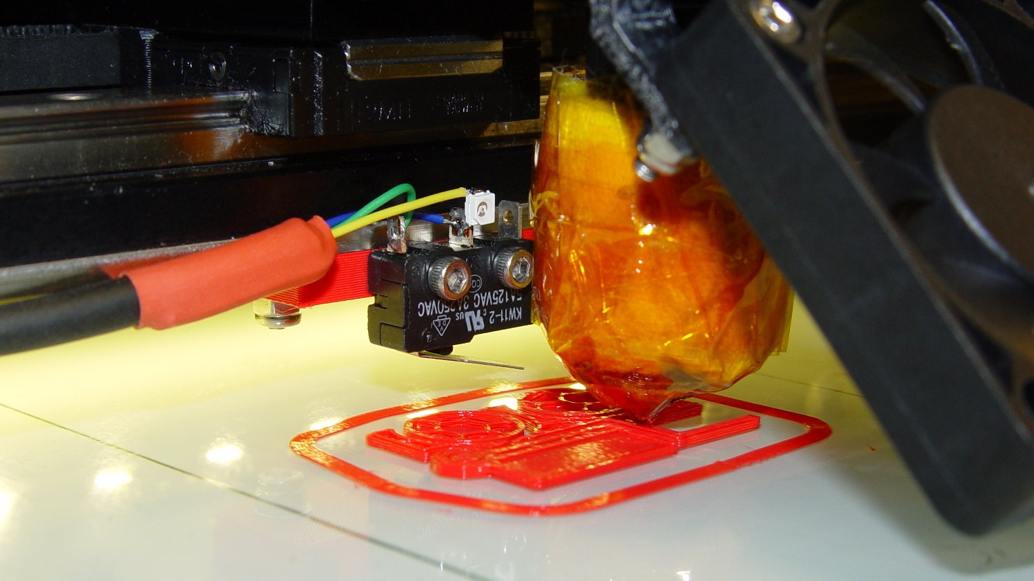
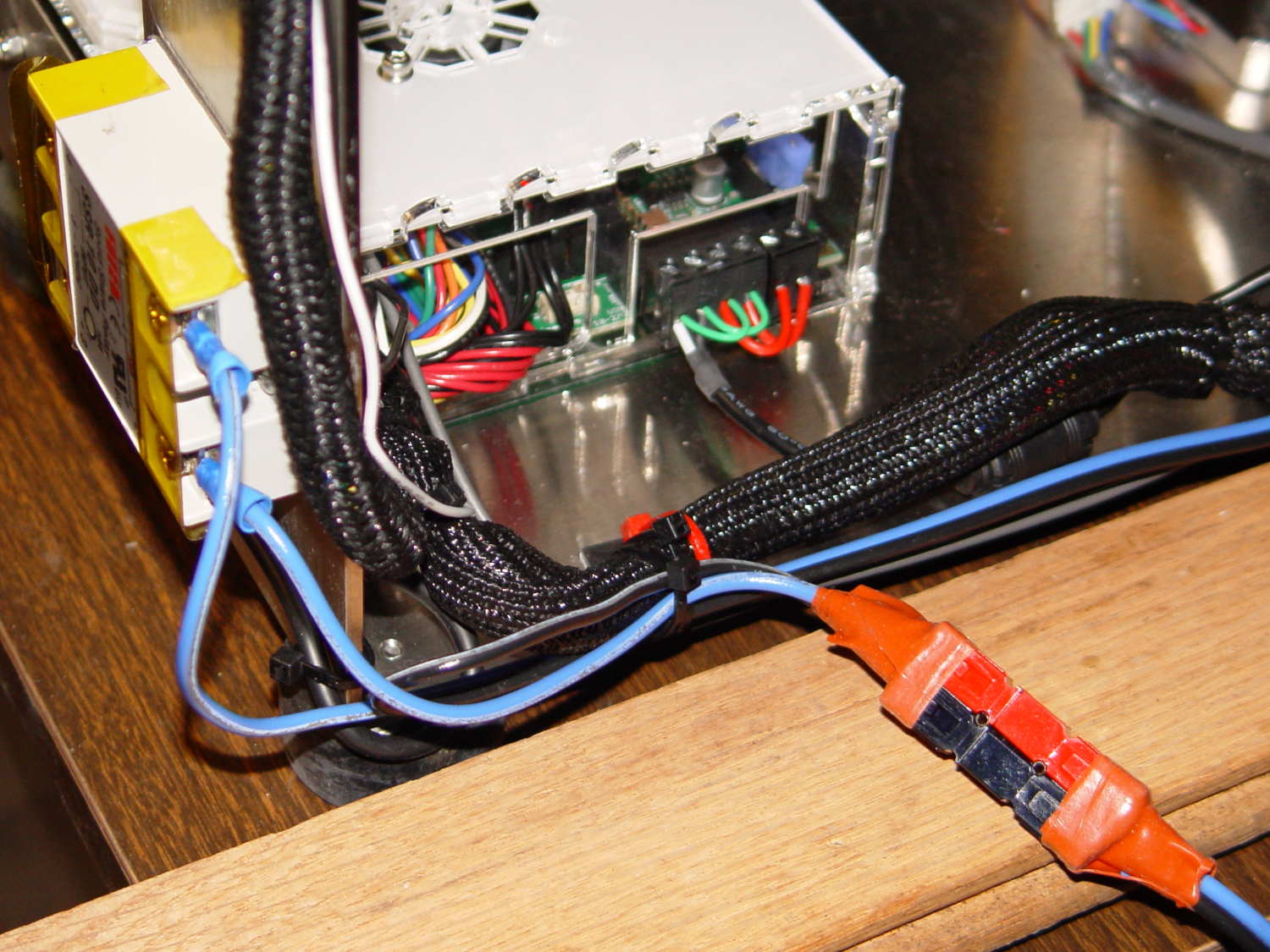
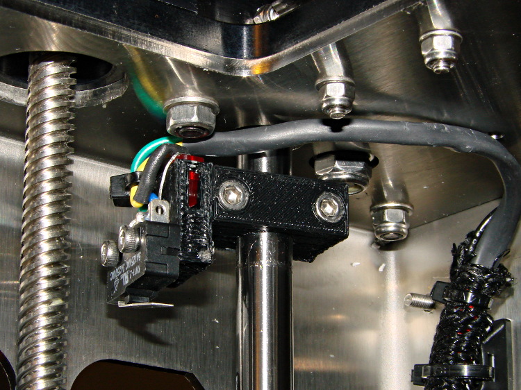
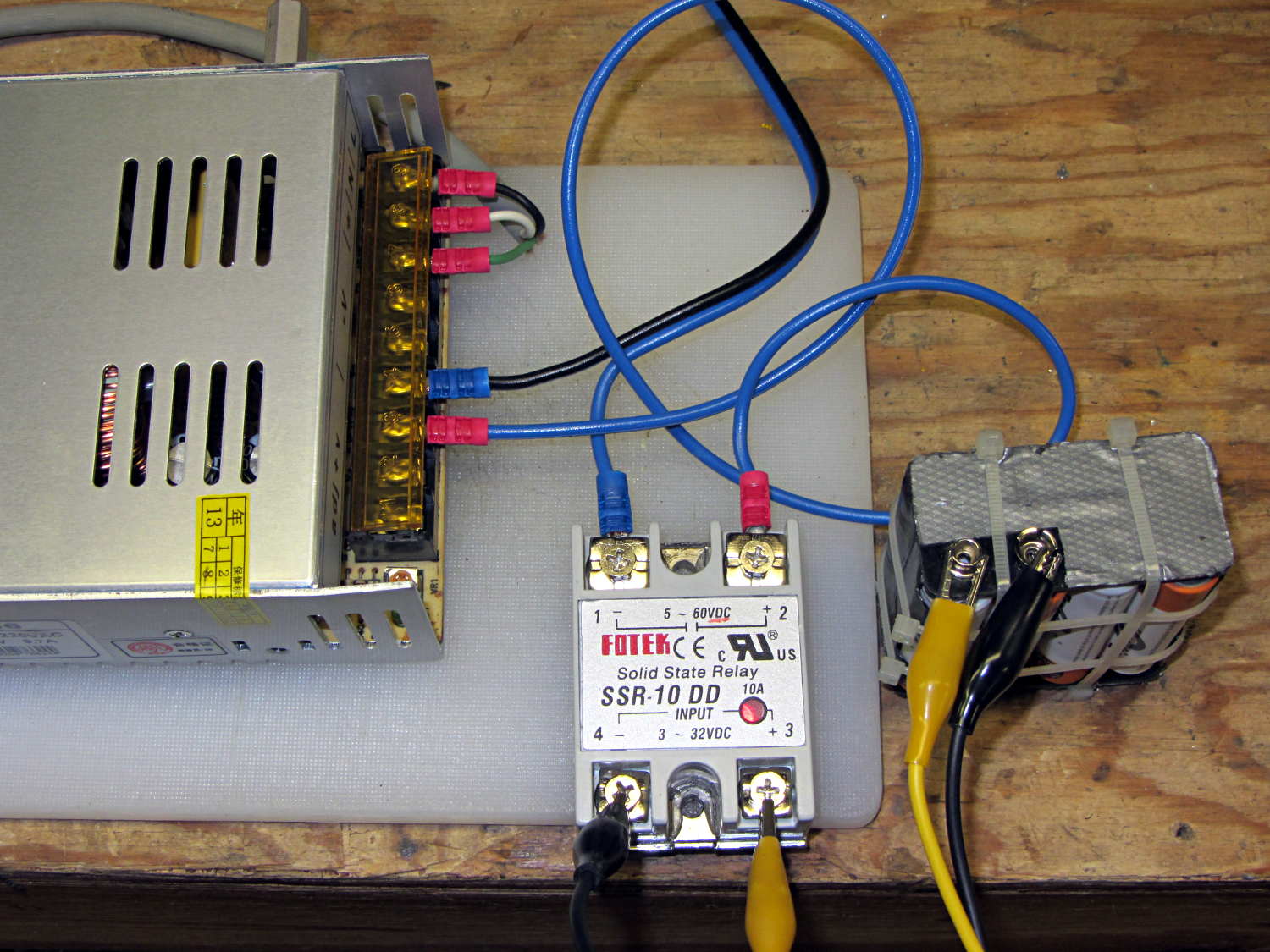
The Makergear M2 comes with a plastic block that covers the X-min switch wiring and anchors the end of the filament guide. Because the guide wasn’t anchored to the block, bumping the guide tended to bend the filament where it exited the block. To prevent that, I hot-melt-glued the guide to the block, which really wasn’t particularly elegant. This picture shows the X-min switch relocated to contact the platform, with the slightly out of focus blob anchoring the guide off to the right:

Makergear provides STL files of the M2’s printable bits, including several versions of the wire cover block. This corresponds to the one on my M2, although the rounded edges don’t come through in the plastic very welll:

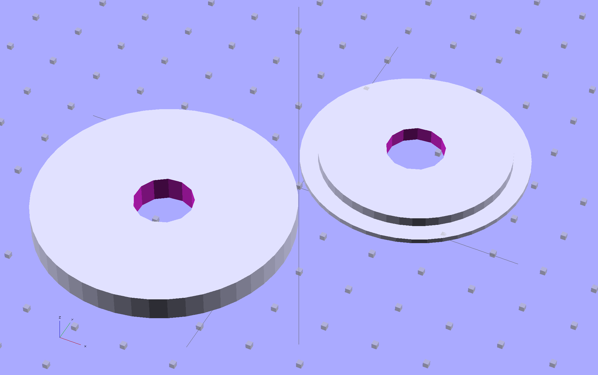
Because STL files aren’t editable, I reverse-engineered the dimensions into an OpenSCAD model that I could use as the basis for a different guide. This is just the basic wire cover, minus the filament guide extension, plus a flat end that wraps around the edge of the chassis:

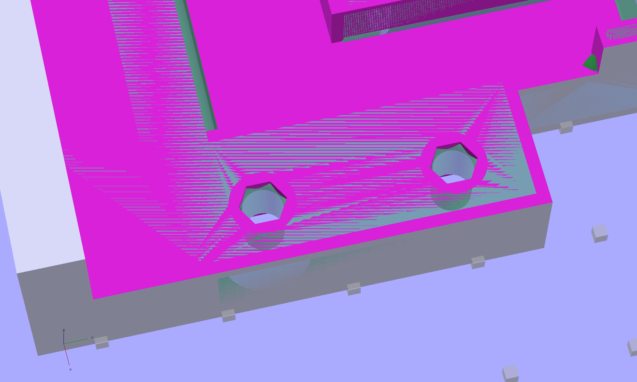
The trick is to import the STL into OpenSCAD, then build a model that matches the key dimensions. Fortunately, Makergear used hard metric sizes for everything, so most of the numbers came out as integers or single-place decimals:

The shimmer indicates coincident surfaces; that’s ordinarily a Very Bad Thing, but in this case it shows that the dimensions match. The top of the holes have neat hexagonal patterns where my straight-sided PolyHoles extend through their chamfered circular holes:
Unlike my from-scratch OpenSCAD models, this one bristles with magic numbers that describe the dimensions of the M2 STL model. The basic shape comes from an extruded polygon matching the outside walls, another extruded polygon knocking out the wire channel, then cubes lopping off the top surfaces:
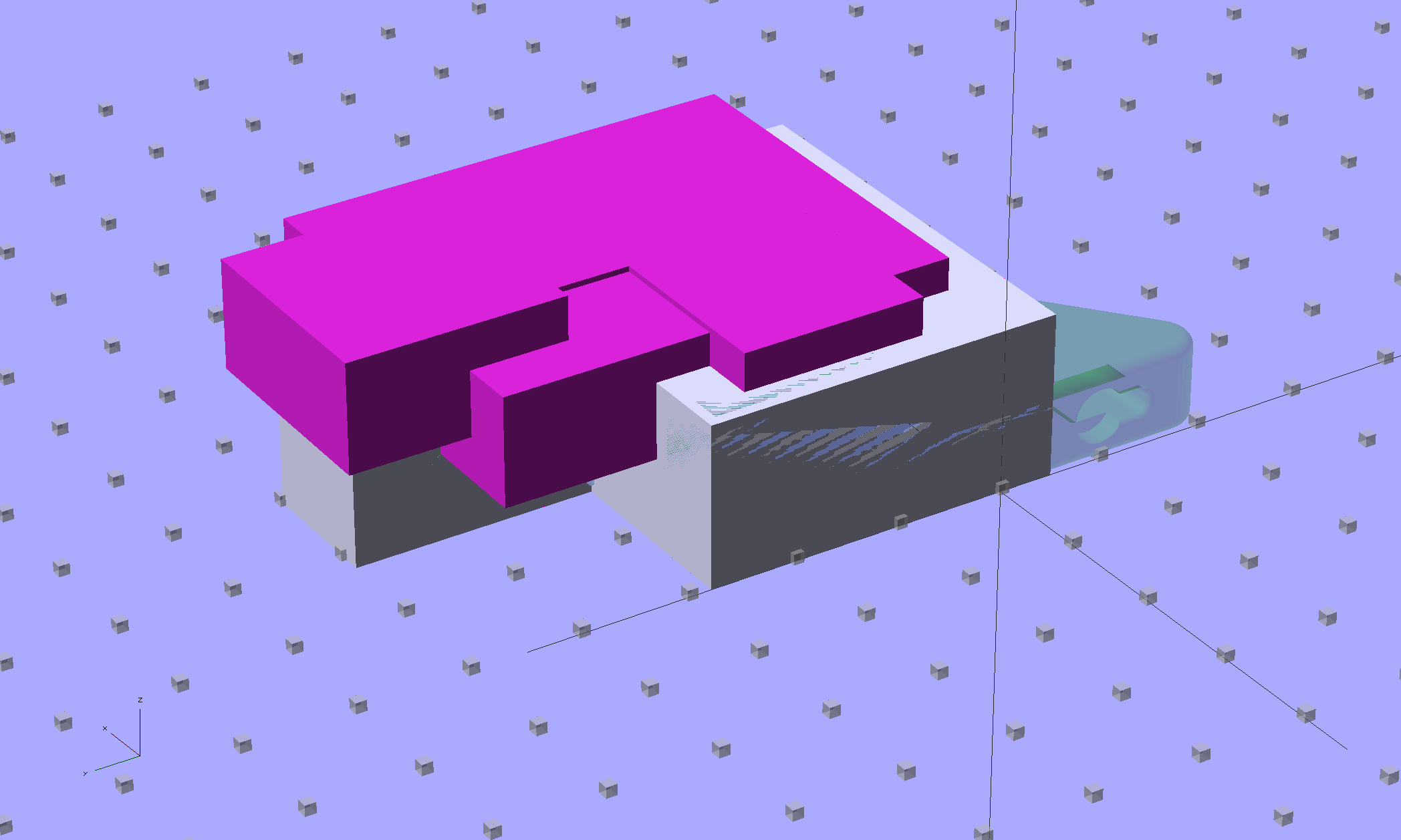
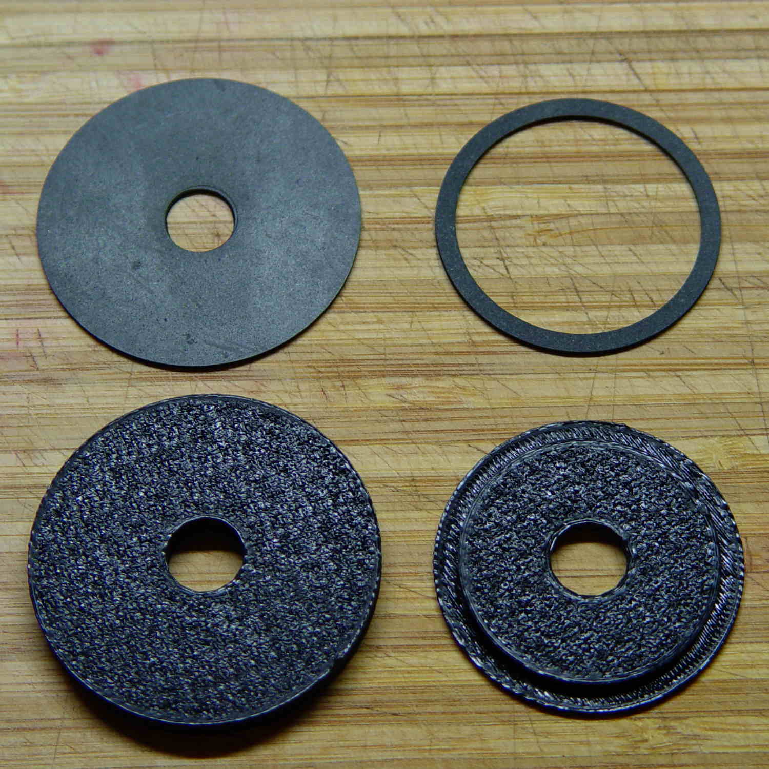
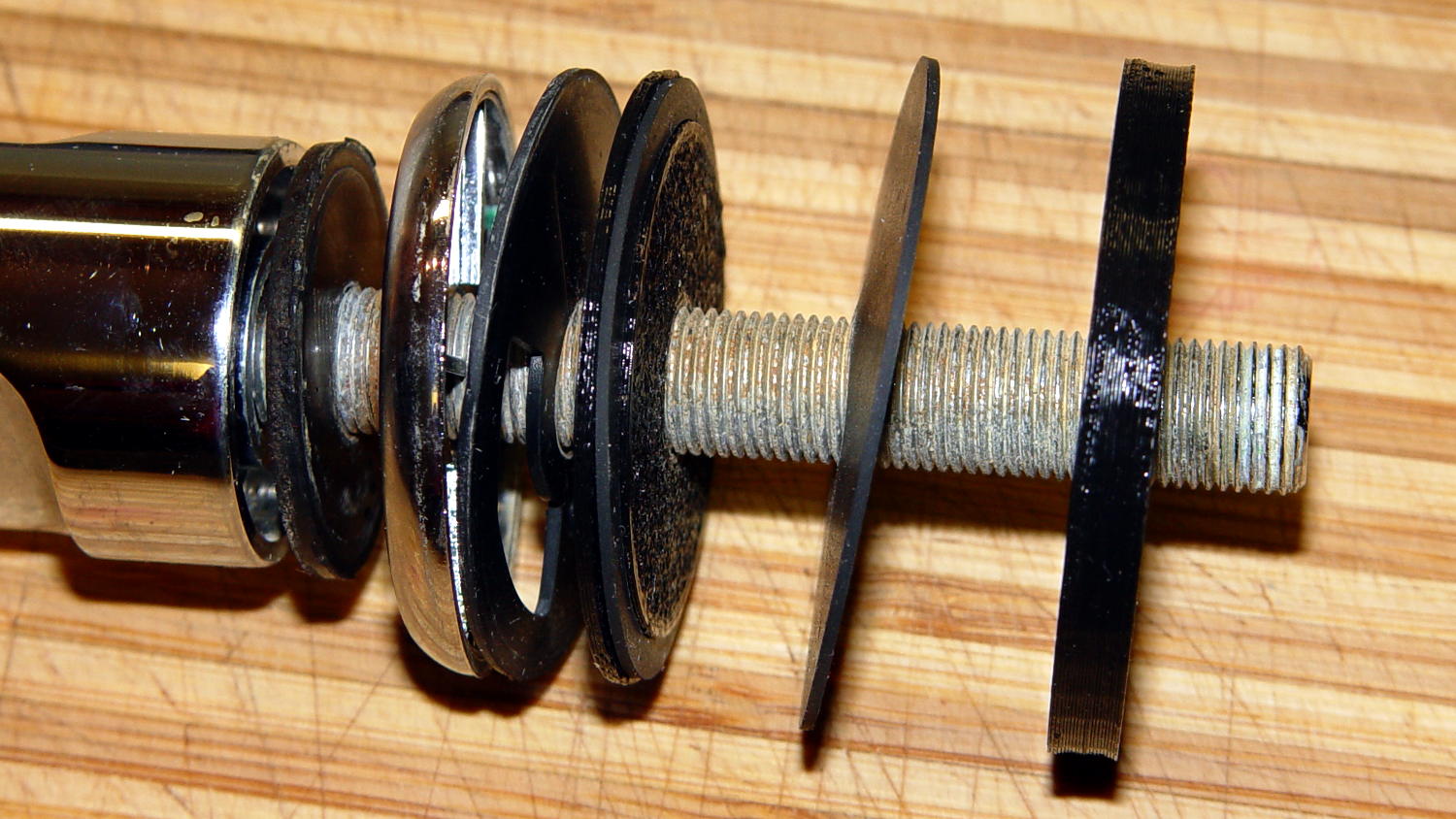
The end result of all that thrashing around has a certain Soviet Concrete look to it:

This version lacks the filament guide; I wanted to make sure all the protrusions and channels fit, which they sort of did:

The next version will have slightly more clearance on the side and slightly less on the top; that’s easy to do now that I have an editable OpenSCAD model.
The OpenSCAD source code:
// Improved M2 filament guide and X-min switch wire guide
// Ed Nisley KE4ZNU - Oct 2013

function IntegerMultiple(Size,Unit) = Unit * ceil(Size / Unit);

Protrusion = 0.1;

HoleWindage = 0.2;

//- Sizes

PlateMinThick = 8.0;				// basic thickness excluding wire guides
PlateLength = 5.0;					// from side of frame beyond top wire guide

TopGuideLength = 7.0;				// protrusion from plate

PlateThick = PlateMinThick + TopGuideLength;

echo(str("Total thickness: ",PlateThick));

//- Adjust hole diameter to make the size come out right

module PolyCyl(Dia,Height,ForceSides=0) {			// based on nophead's polyholes

  Sides = (ForceSides != 0) ? ForceSides : (ceil(Dia) + 2);

  FixDia = Dia / cos(180/Sides);

  cylinder(r=(FixDia + HoleWindage)/2,h=Height,$fn=Sides);
}

//- Put peg grid on build surface

module ShowPegGrid(Space = 10.0,Size = 1.0) {

  RangeX = floor(100 / Space);
  RangeY = floor(125 / Space);

	for (x=[-RangeX:RangeX])
	  for (y=[-RangeY:RangeY])
		translate([x*Space,y*Space,Size/2])
		  %cube(Size,center=true);

}

//- Define basic block shape
//  Mostly reverse engineered from
//    https://github.com/MakerGear/M2/blob/master/Printed%20Parts/STL/M2%20X%20Endstop%20Wire%20Cover%20with%20Filament%20Guide.stl
//	Hence all the magic numbers...

module BaseBlock() {

SideGuideLength = 4.0;				// protrusion = even with frame interior
ChannelDepth = 4.5;					// wiring channel
FrameOffset = 28;

	translate([18,FrameOffset,0]) {			// align neatly for later processing

		if (true)
			color("Green",0.3)
				translate([-18,22,15])
					rotate([-90,0,-90])
						import("/mnt/bulkdata/Project Files/Thing-O-Matic/M2 Parts/Filament Guide/M2+X+Endstop+Wire+Cover+with+Filament+Guide.stl",
								convexity=10);

		difference() {
			linear_extrude(height=PlateThick,convexity=5)		// main block
				polygon(points=[[0,0],[0,22],[12,22],[12,7.5],[22,7.5],
								[22,-(PlateLength + FrameOffset)],[-18,-(PlateLength + FrameOffset)],
								[-18,0]
						]);

			for (i=[-1,0])
				translate([17,((i*15.0)+ 1.05),-Protrusion])
					rotate(180/6) {
						PolyCyl(3.1,(PlateMinThick + 2*Protrusion),6);		// screw holes
						PolyCyl(5.7,(3.0 + Protrusion),6);					//  ... countersink
					}

			translate([0,0,(PlateMinThick - ChannelDepth)])		// wire channel
				linear_extrude(height=15,convexity=5)
					polygon(points=[[2,-5],[2,19],[10,19],[10,-22],[-15,-22],[-15,-5]
							]);

			translate([-10,14,PlateMinThick])				// M2 frame
				rotate(-90)
					cube([42,35,10],center=false);

			translate([-5,5,(PlateMinThick + SideGuideLength)])	// shorten side guide
				cube([20,20,10],center="false");

		}
	}

}

//- Build it

ShowPegGrid();

BaseBlock();