Ed Nisley's Blog: Shop notes, electronics, firmware, machinery, 3D printing, laser cuttery, and curiosities. Contents: 100% human thinking, 0% AI slop.
Tag: Improvements
Making the world a better place, one piece at a time
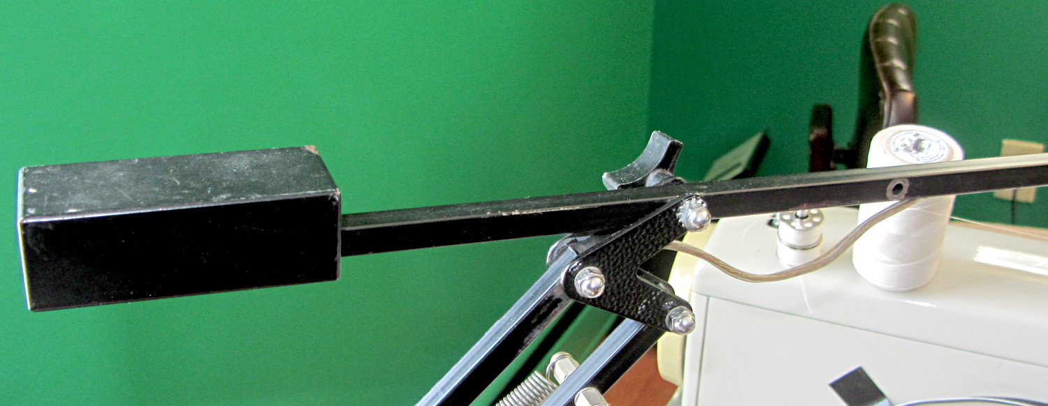
Moving the pivot point of the rebuilt desk lamp arm back about 75 mm put it at the proper spot:
Rebalanced desk lamp boom
That required snaking new wiring from the transformer in the base through the upright and out through the boom to the LED floodlamp. I used a random length of speaker cable from the Big Box o’ Heavy Wires, although it doesn’t take much to carry 300 mA at 12 V.
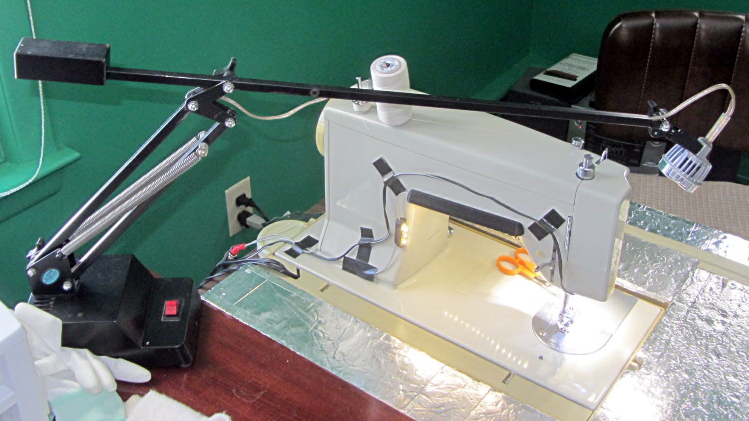
The lamp head now reaches the work area and the base stays out of the way:
Rebuild desk lamp over sewing machine
It is, we both agree, hideously ugly, but it puts plenty of light at the right spot.
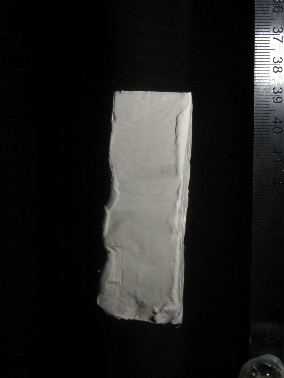
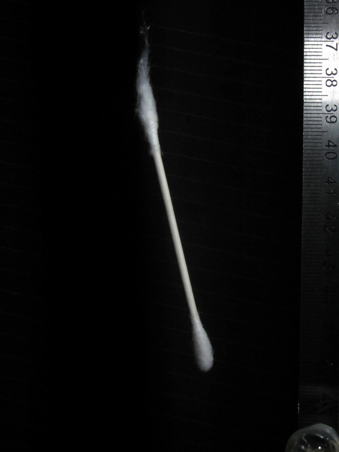
A black background does wonders to improve the presentation:
Clay slab – 180 ms
That’s ISO 800, 1/10 s, f/8, 30 cm manual focus, with the flash about 20 cm away in the right foreground. The Xenon flash has a 1 µF capacitor giving a pulse width of about 100 µs. The LED visible on the lower right flashed 1 ms after the lump broke the laser beam.
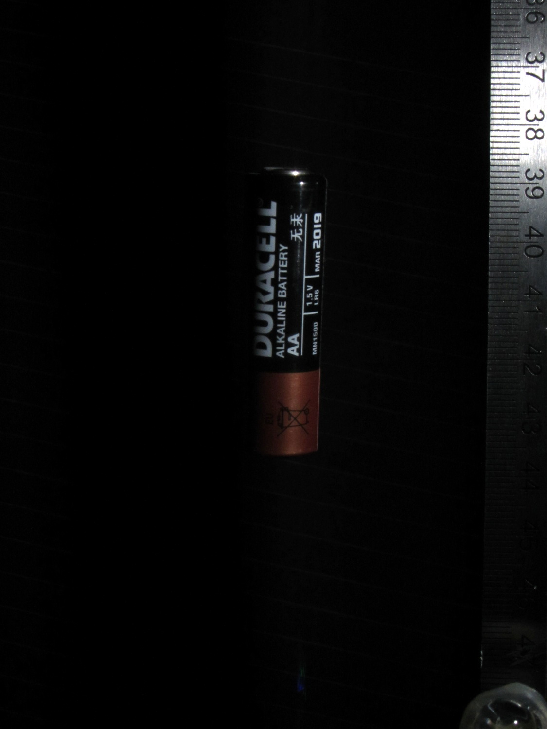
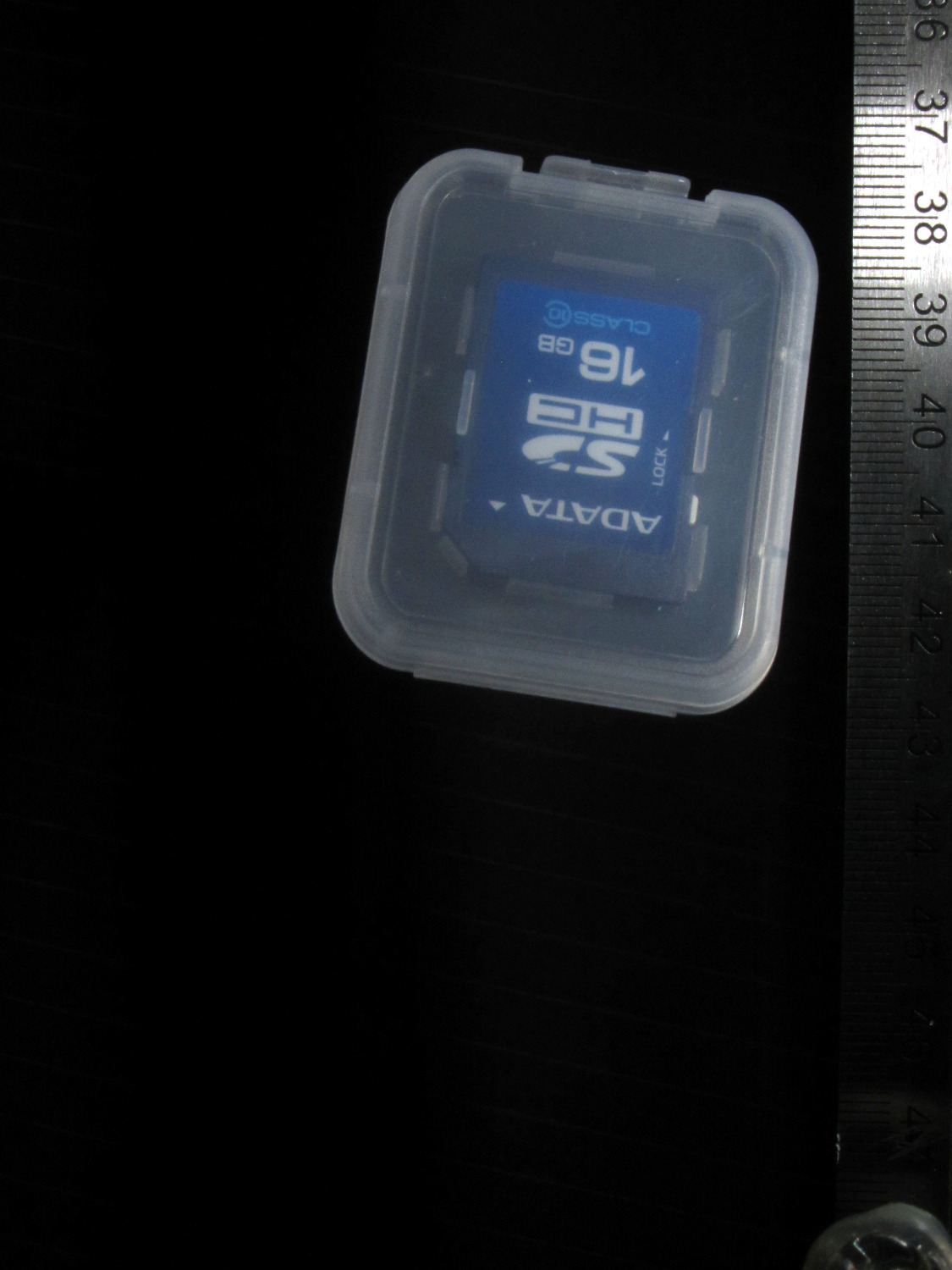
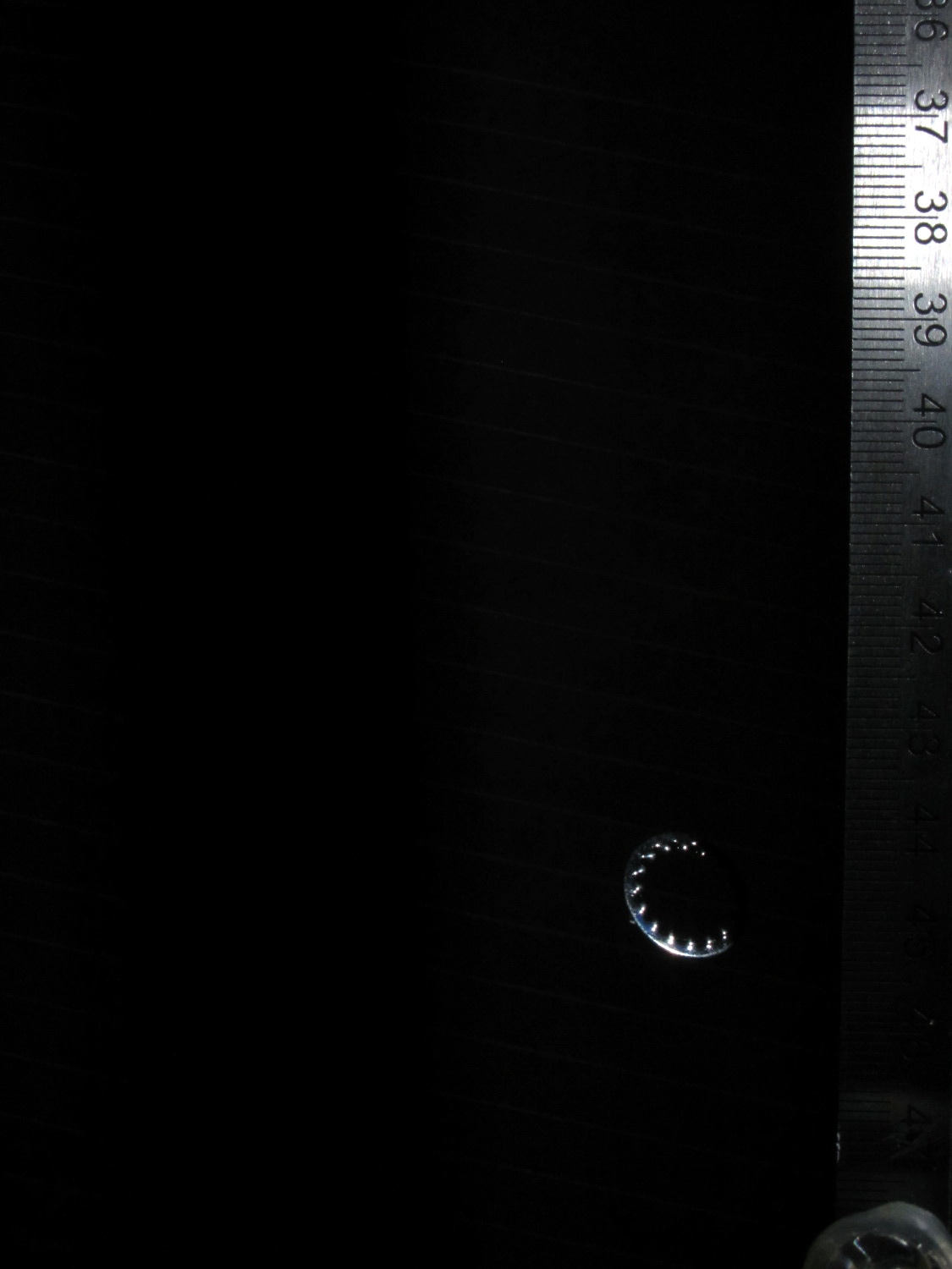
Rather than do science, I shoveled small objects through the aperture…
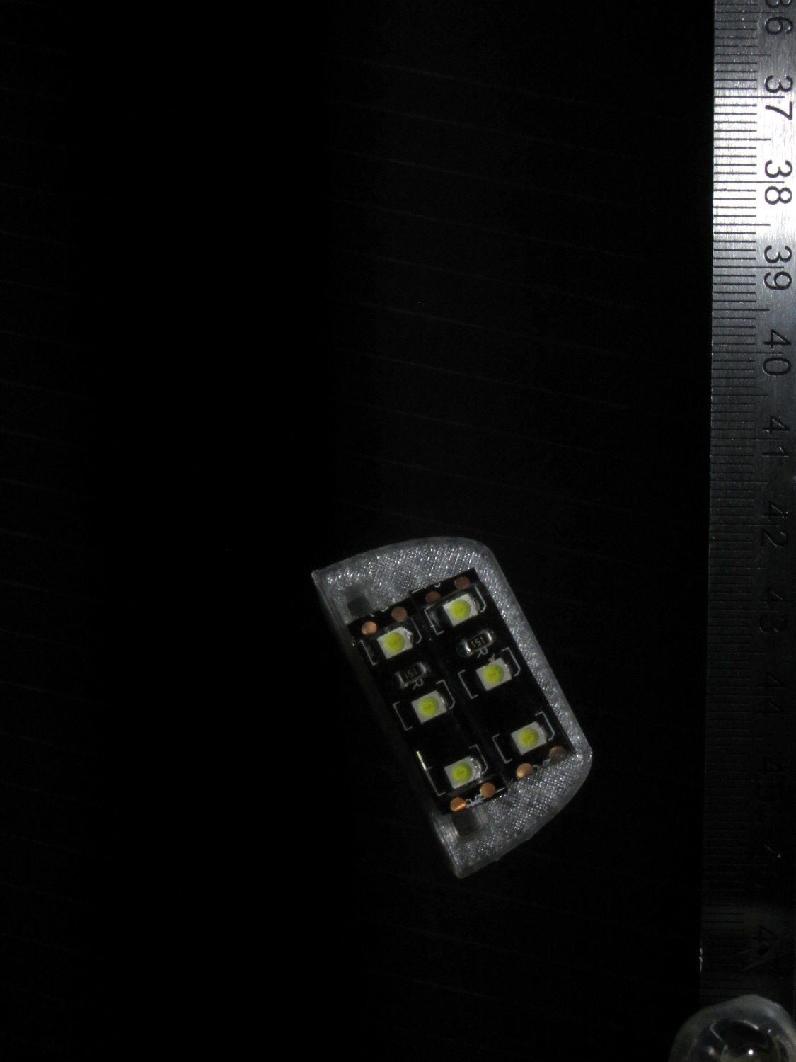
Falling LED striplightFalling Sierpinski gasketFalling clay blockFalling cotton swabFalling AA cellFalling SDHC CardFalling lock washer
Tweaking the Arduino program to fire the LED 10 ms after the beam breaks, then fire the Xenon strobe 180 ms later produces this result:
Drop test – ISO 800 – 100 ms f8 – overexposure
Obviously, that’s far too much light: ISO 800, 1/10 sec, f/8, with the flash a few inches from the action. There aren’t many free variables:
Shutter must be open long enough to span the timing jitter
Aperture is already as small as it gets for good depth of focus
ISO speed may be too high
Flash intensity is fixed for a given capacitor
Throwing a shop rag over the flash helps a bit, capturing the ruler suspended in mid-air:
Drop test – ISO 800 – 100 ms f8 – cloth
However, replacing the 250 µF electrolytic flash capacitor with a 1 µF film cap reduces the stored energy by roughly an order of magnitude and reduces the flash pulse duration to about 100 µs.
The bottom two inches of the ruler now have lighting from the flash, while the rest of the image looks pretty good in natural light:
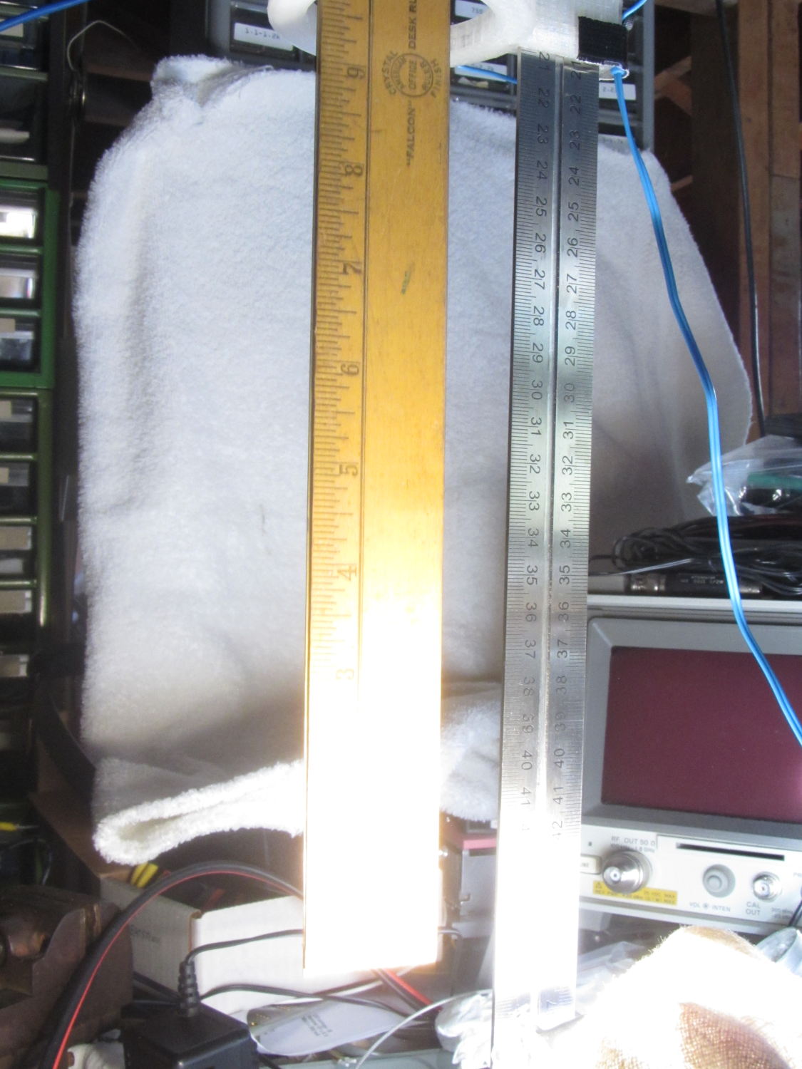
Drop test – ISO 800 – 100 ms f8 – 1 uF
It turns out that having the laser and photodiode beam-break sensor within the view (the white ring at the top) doesn’t work, as the CHDK motion detector will notice the red spot on the ruler and trigger the shutter before the LED (clipped to the right of the vertical steel scale) flashes.
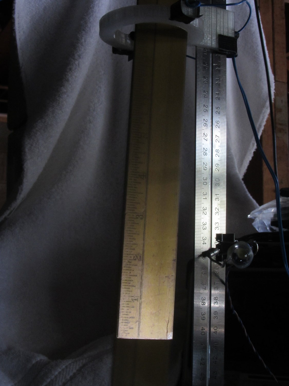
Several more trials showed that the flash fires consistently, but (as expected) the shutter triggering has some jitter. In this case, the shutter remained open after the flash and captured a blurred image as the ruler continued to fall:
Drop test – ISO 800 – 100 ms f8 – tail
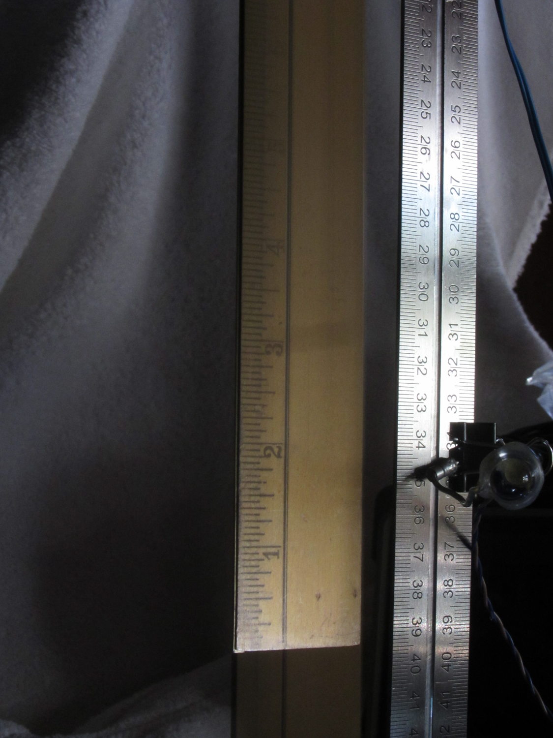
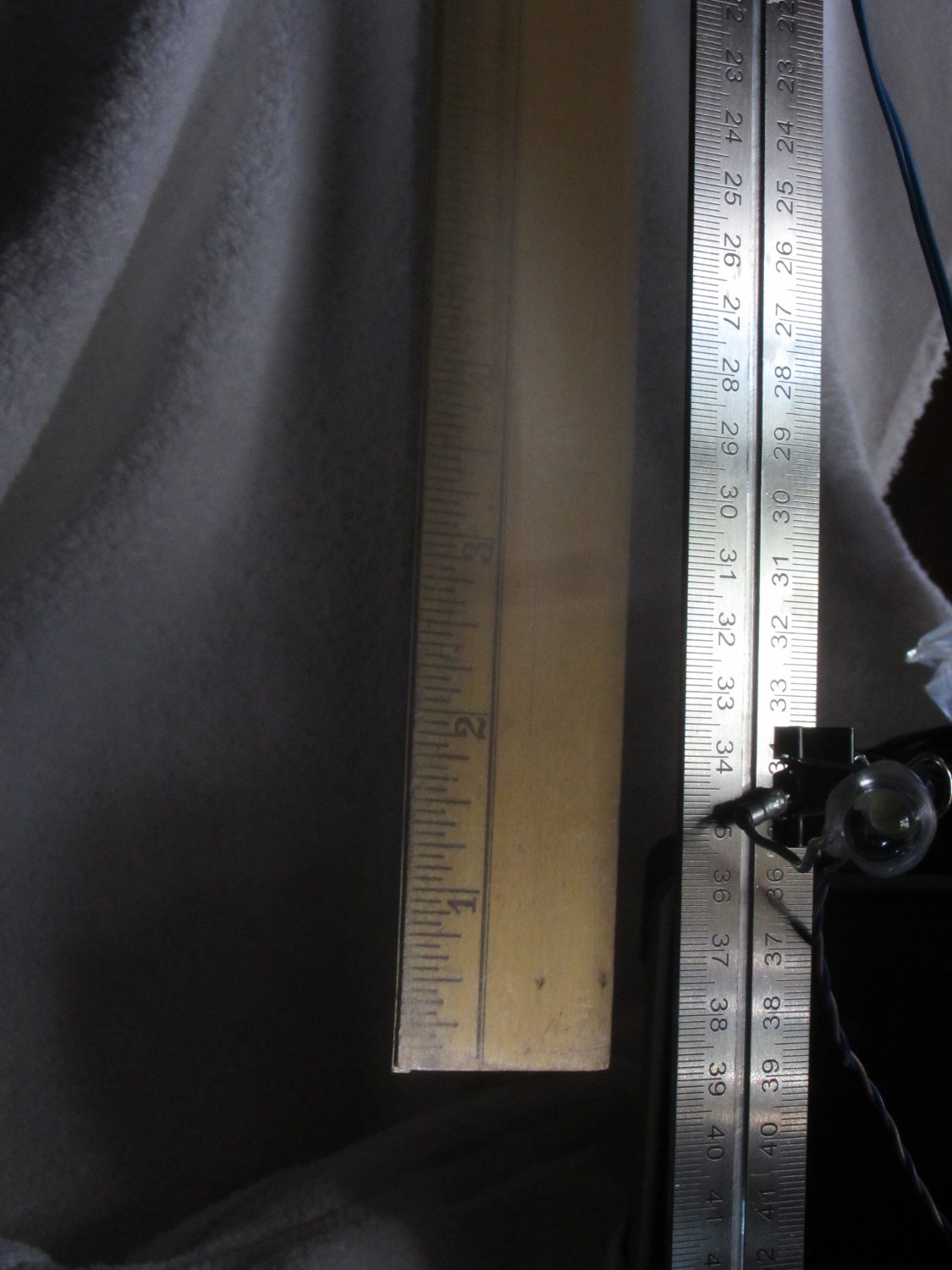
Here, the shutter closed immediately after the flash, eliminating the blurred tail:
Drop test – ISO 800 – 100 ms f8 – no tail
Having the shutter close before the object reaches the bottom of the image is a Bad Thing, as it means the shutter triggered too early.
In both cases, the sharp image of the ruler overlays the blurred image captured in natural light. That’s more visible toward the top of the picture where the flash doesn’t reach very well.
I aligned the laser beam-break detector at 200 mm on the scale and the flash fired when the tip of the ruler was at 390 mm = 190 mm below the beam. The LED blinked 10 ms after the beam break and the Xenon flash fired at 180 ms; given all the vagaries involved, 190 mm is just about spot on the (revised) estimates.
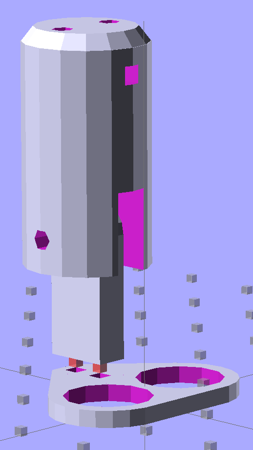
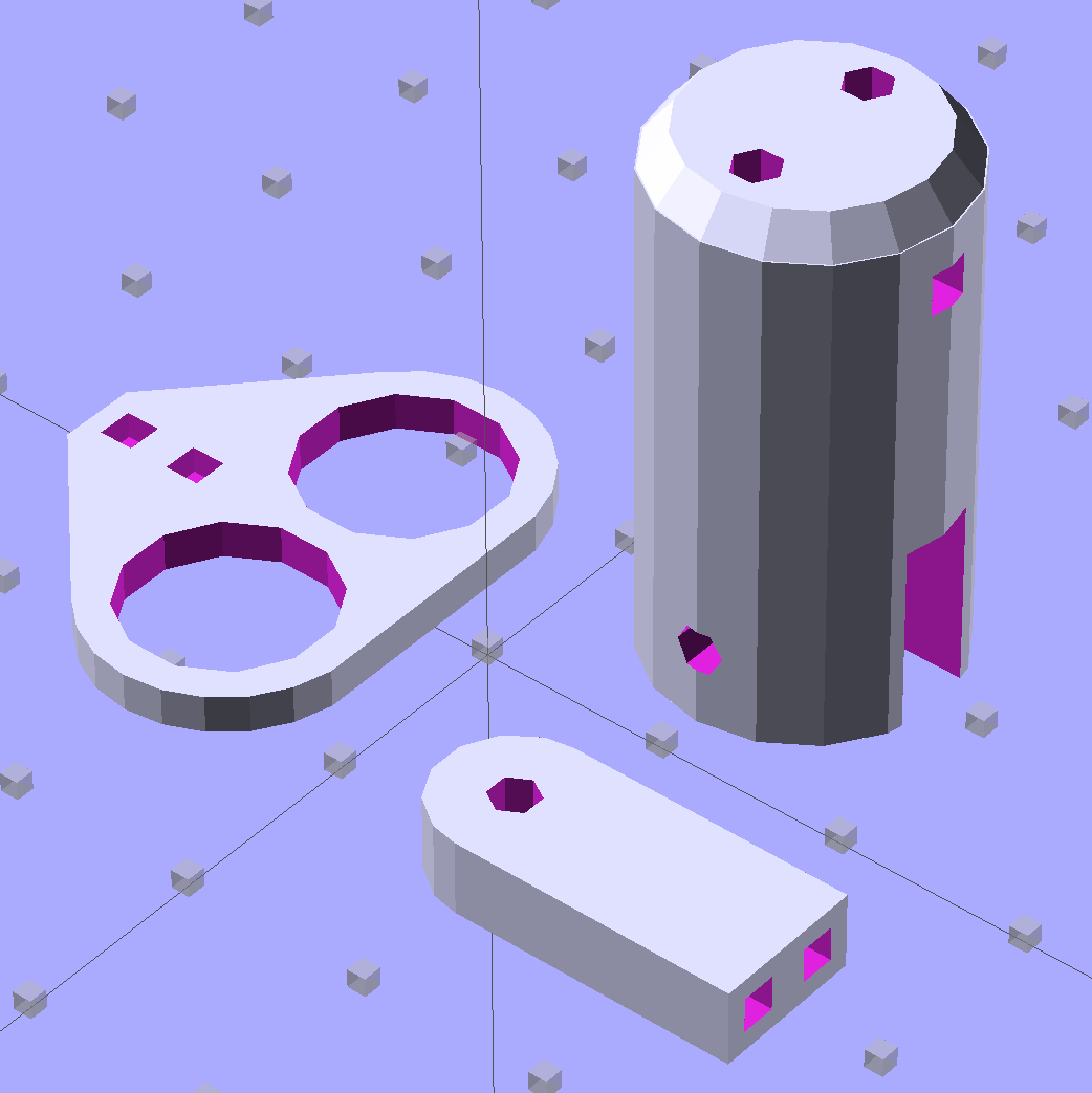
Some trial fitting with the prototype showed that there’s no possible way to route the connections through the socket, no matter how much I wanted that to happen, so I rotated the body to align the LEDs with the socket pin slots:
Sears Lamp LED Adapter – Show view
The body now builds with the flat end down, so the overall finish should be better:
Sears Lamp LED Adapter – Build view
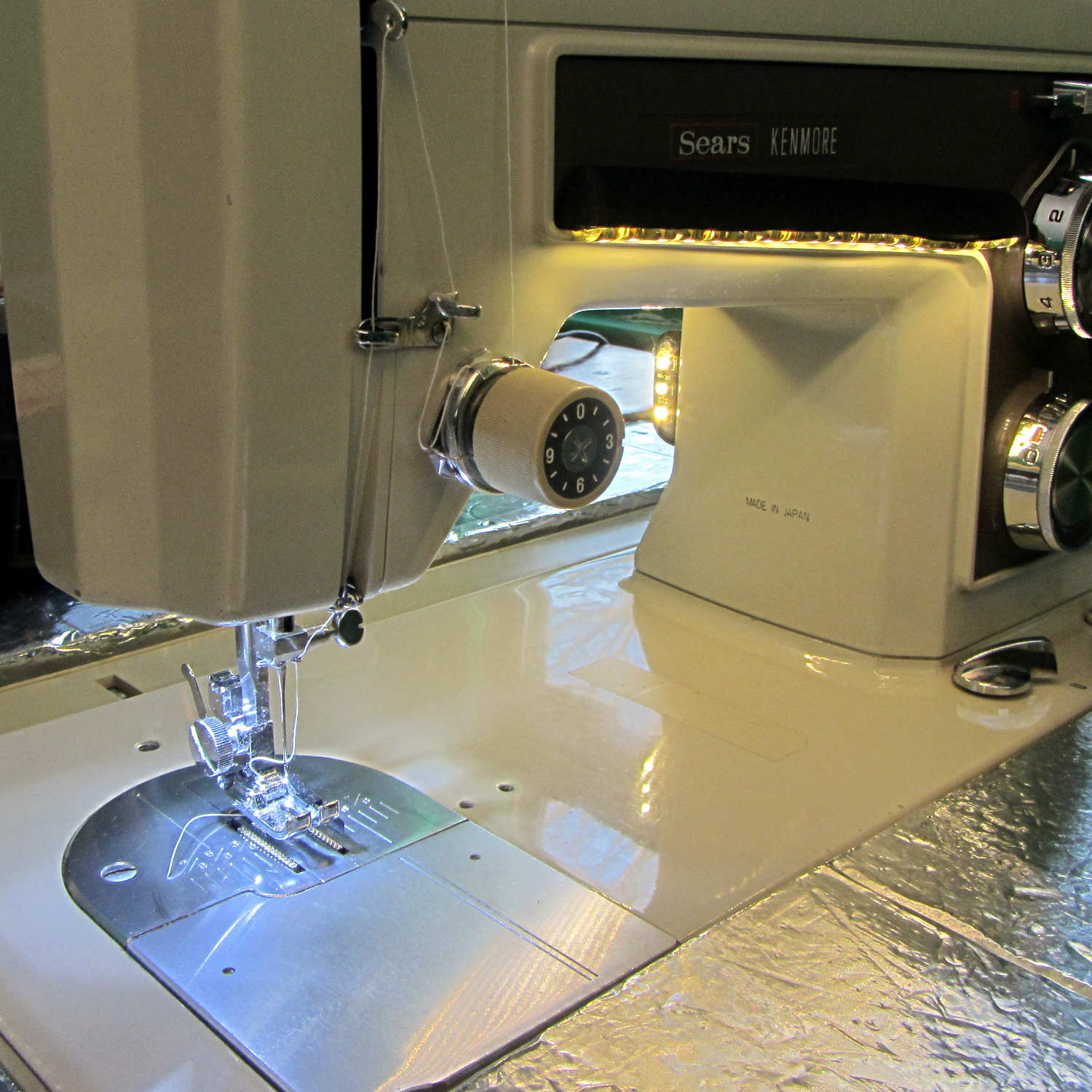
A test run shows why I really, really wanted cool white LEDs in the strips over the arm:
Kenmore 158 Sewing Machine – mixed LED lighting
The LED mount doesn’t have quite enough room inside the end cap for the holder to tilt as I wanted; the two 10 mm LEDs can be about 10 mm lower and slightly closer to the shaft driving the needle, which is what this rapid prototyping stuff is all about. Scrapping the existing lamp socket and (120 VAC!) wiring seems the best way to make this more useful.
Early reports on the arm LEDs indicate a requirement for more light, so the next iteration of those mounts will put two strips side-by-side…
Solder pretty cable with silver plating on the braid (it’s probably mil-spec Teflon dielectric RG-174 coaxial cable) to the LEDs
Conjure a coax power connector and wall wart
Apply foam squares to mounts
Affix to sewing machine
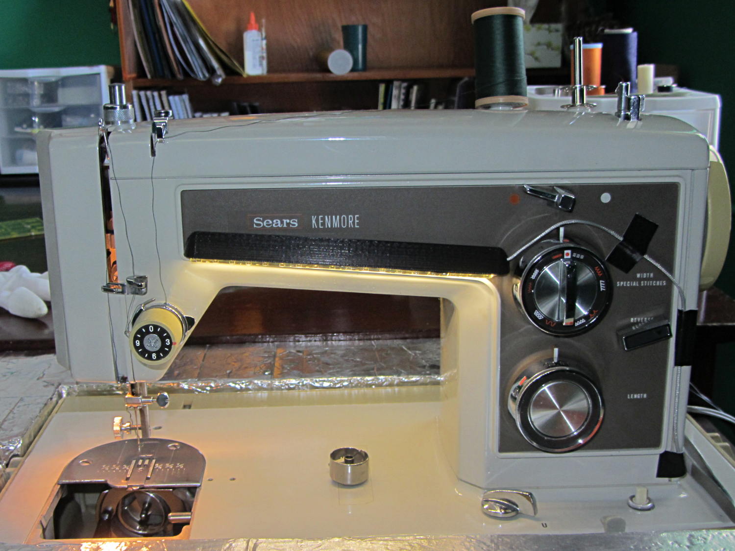
The front LEDs have a jaunty angle along the bottom of the plastic panel:
Kenmore Model 158 Sewing Machine – LED Lights – front
You can see why I want cool-white LEDs, rather than these warm-white ones, to match the daylight from the window to the right. The wash of orange light from the incandescent bulb inside the end bell has got to go, too.
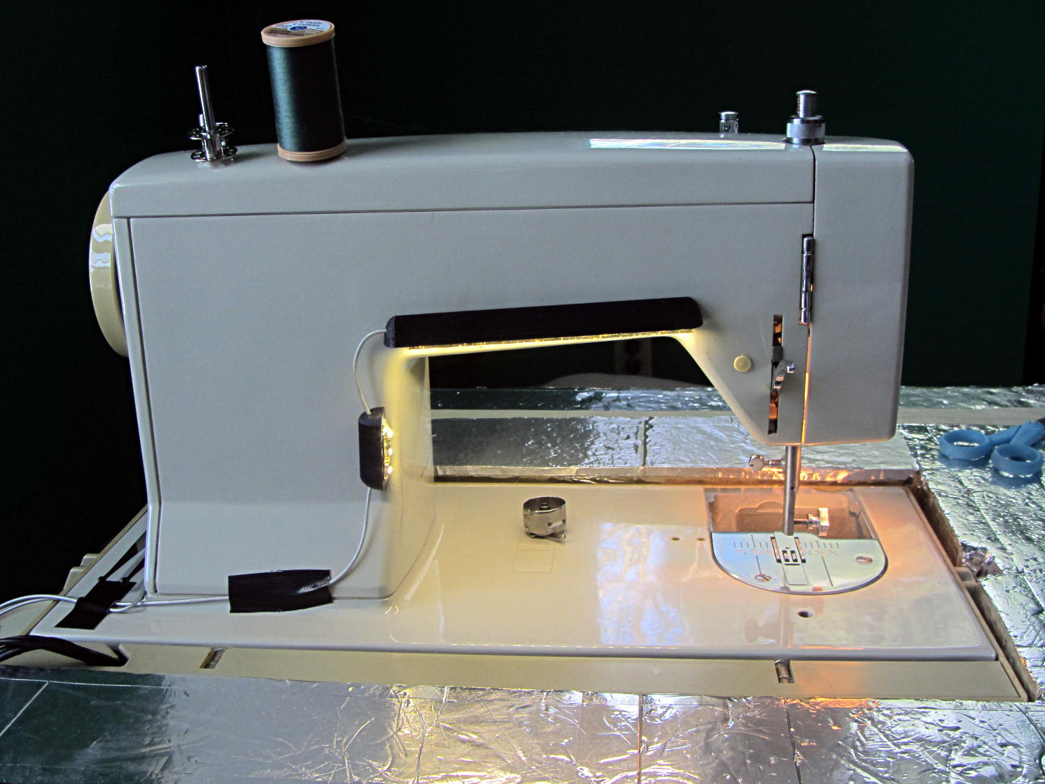
The rear LEDs over the arm may be slightly too close to the opening:
Kenmore Model 158 Sewing Machine – LED Lights – rear
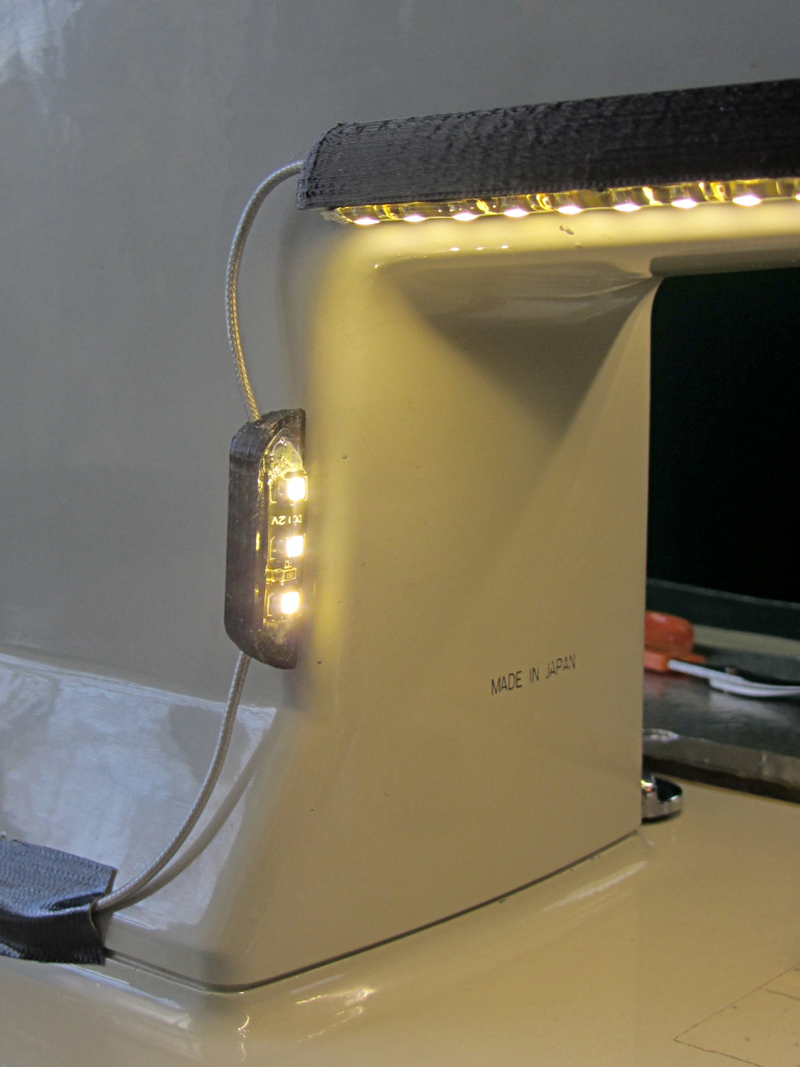
The single-segment strip on the side provides a bit more light for the needle across the opening:
Kenmore Model 158 Sewing Machine – LED Lights – rear detail
Now, I’ll grant you that the strips of of black Gorilla Tape aren’t particularly attractive, but the intent here is to find out whether the LEDs produce enough light, don’t snag the quilt, and generally meet requirements.
My old Thing-O-Matic has new life as the Frank-O-Squid at Squidwrench Galactic HQ, with all the original Makerbot electronics replaced by an Azteeg X3 controller. Over the last several weeks I’ve coaxed it into doing most of the right things at the proper speeds & feeds, so we can now move on to actually making stuff:
Frank-o-Squid in action
The warping on that little digital caliper thumbwheel holder show that I don’t have the tiny-object slowdown settings quite correct, but it’s getting close.
The Marlin firmware is on GitHub. I intended to set it up so that pulling changes from upstream Marlin would be easy, but totally blundered something along the way. I’ll eventually plug the changes from Configuration.h, Configuration_adv.h, and pins.h into a clean branch and start over, but, for now, we’re slowly diverging from consensus reality.
Although the platform still has the Z-min switch over on the right edge, neither the firmware nor Slic3r pay any attention to it. A stub in the startup G-Code sequence does a head fake toward the switch, but doesn’t actually probe it.
I scrapped the original craptastic Makerbot ATX power supply and replaced it with Makergear’s huge 12 V laptop brick that powered the original M2 platform, so the thermal switches on the extruder no longer do anything useful; it’s running bare, pretty much like all other 3D printers.
The Slic3r configuration exports thusly:
# generated by Slic3r 1.0.0RC1 on Mon Mar  3 07:48:29 2014
avoid_crossing_perimeters = 0
bed_size = 105,120
bed_temperature = 100
bottom_solid_layers = 3
bridge_acceleration = 0
bridge_fan_speed = 100
bridge_flow_ratio = 1
bridge_speed = 40
brim_width = 1.0
complete_objects = 0
cooling = 1
default_acceleration = 0
disable_fan_first_layers = 1000
duplicate = 1
duplicate_distance = 6
duplicate_grid = 1,1
end_gcode = ;---- end.gcode starts ----\n; TOM 286 - Al plates + Geared extruder\n; Ed Nisley - KE4ZNU - January 2014\n; Marlin with tweaks for Azteeg X3 with thermocouple\n;- inhale filament blob\nG91\nG1 E-5 F900\nG90\n;- turn off heaters\nM104 S0         ; extruder head\nM140 S0         ; HBP\n;- move to eject position\nG0 Z115 F1000   ; home Z to get nozzle away from object\n;G92 Z115      ; reset Z\nG1 X0 F6000     ; center X axis\nG1 Y35          ; move Y stage forward\n;---- end.gcode ends ----
external_perimeter_speed = 50%
external_perimeters_first = 0
extra_perimeters = 1
extruder_clearance_height = 20
extruder_clearance_radius = 20
extruder_offset = 0x0
extrusion_axis = E
extrusion_multiplier = 0.95
extrusion_width = 0.50
fan_always_on = 0
fan_below_layer_time = 1
filament_diameter = 2.95
fill_angle = 45
fill_density = 0.15
fill_pattern = honeycomb
first_layer_acceleration = 0
first_layer_bed_temperature = 100
first_layer_extrusion_width = 0.50
first_layer_height = 0.25
first_layer_speed = 10
first_layer_temperature = 210
g0 = 0
gap_fill_speed = 30
gcode_arcs = 0
gcode_comments = 0
gcode_flavor = reprap
infill_acceleration = 0
infill_every_layers = 2
infill_extruder = 1
infill_extrusion_width = 0.50
infill_first = 1
infill_only_where_needed = 1
infill_speed = 50
layer_gcode =
layer_height = 0.25
max_fan_speed = 100
min_fan_speed = 35
min_print_speed = 10
min_skirt_length = 3
notes =
nozzle_diameter = 0.4
only_retract_when_crossing_perimeters = 1
ooze_prevention = 0
output_filename_format = [input_filename_base].gcode
overhangs = 1
perimeter_acceleration = 0
perimeter_extruder = 1
perimeter_extrusion_width = 0.50
perimeter_speed = 30
perimeters = 1
post_process =
print_center = 0,0
raft_layers = 0
randomize_start = 1
resolution = 0.05
retract_before_travel = 0.0
retract_layer_change = 0
retract_length = 0.75
retract_length_toolchange = 10
retract_lift = 0
retract_restart_extra = 0
retract_restart_extra_toolchange = 0
retract_speed = 30
rotate = 0
scale = 1
skirt_distance = 2
skirt_height = 1
skirts = 1
slowdown_below_layer_time = 30
small_perimeter_speed = 50%
solid_fill_pattern = rectilinear
solid_infill_below_area = 5
solid_infill_every_layers = 0
solid_infill_extrusion_width = 0.50
solid_infill_speed = 150%
spiral_vase = 0
standby_temperature_delta = -5
start_gcode = ;---- start.gcode begins ----\n; TOM 286 - Al plates + Geared extruder + Zmin platform sense\n; Ed Nisley - KE4ZNU - January 2014\n; Marlin with tweaks for Azteeg X3 with thermocouple\n;\n; Set initial conditions\nG21                 ; set units to mm\nG90                 ; set positioning to absolute\n;----------\n; Begin heating\nM104 S[first_layer_temperature]         ; extruder head\nM140 S[first_layer_bed_temperature]	; start bed heating\n;----------\n; Home axes\nG28 X0 Y0 Z0\nG92 X-53.5 Y-58.5 Z114.5\n;----------\n; Initial nozzle wipe to clear snot for Z touchoff\nG1 X0 Y0 Z3.0 F1000     ; pause at center to build confidence\nG4 P1000\nG1 Z10                  ; ensure clearance\nG1 X39 Y-58.0 F1000    ; move to front, avoid wiper blade\nG1 X55                  ; to wipe station\nG1 Z6.0                 ; to wipe level\nM116                    ; wait for temperature settling\nG1 Y-45 F500            ; slowly wipe nozzle\n;-----------------------------------------------\n; Z platform height touchoff\n; Make sure the XY position is actually over the switch!\n; Home Z downward to platform switch\n; Compensate for 0.05 mm backlash in G92: make it 0.05 too low\nG1 X56.0 Y8.2 F5000\nG1 Z4.0 F1000     ; get over build platform switch\n;G1 Z0 F50                    ; home downward very slowly\n;G92 Z1.45                    ; set Z-min switch height\nG1 Z6.0 F1000                ; back off switch to wipe level\n;-----------------------------------------------\n; Prime extruder to stabilize initial pressure\nG1 X55 Y-45 F5000   ; set up for wipe from rear\nG1 Y-58.0 F500      ; wipe to front\nG91                 ; use incremental motion for extrusion\nG1 F100               ; set decent rate\nG1 E10              ; extrude enough to get good pressure\nG1 F2000            ; set for fast retract\nG1 E-1.0            ; retract\nG90                 ; back to absolute motion\nG1 Y-45 F1000       ; wipe nozzle to rear\n;----------\n; Set up for Skirt start in right front corner\n; Compensate for Z backlash: move upward from zero point\nG1 X40 Y-40 F5000\nG1 Z0.0 F1000     ; kiss platform\nG1 Z0.2 F1000       ; take up Z backlash to less than thread height\n;G92 E1.0            ; preset to avoid huge un-Reversal blob\n;G1 X0 Y0\n;---- start.gcode ends ----
start_perimeters_at_concave_points = 1
start_perimeters_at_non_overhang = 1
support_material = 0
support_material_angle = 0
support_material_enforce_layers = 0
support_material_extruder = 1
support_material_extrusion_width = 0.50
support_material_interface_extruder = 1
support_material_interface_layers = 3
support_material_interface_spacing = 0
support_material_pattern = honeycomb
support_material_spacing = 2.5
support_material_speed = 60
support_material_threshold = 0
temperature = 210
thin_walls = 1
threads = 2
toolchange_gcode =
top_infill_extrusion_width = 0.50
top_solid_infill_speed = 50%
top_solid_layers = 3
travel_speed = 150
use_firmware_retraction = 0
use_relative_e_distances = 0
vibration_limit = 0
wipe = 0
z_offset = 0
All of that should become three TOM286 - Default sub-profiles.
The Pronterface configuration looks like this:
set port /dev/ttyUSB0
set monitor True
set last_bed_temperature 100.0
set last_temperature 210.0
set baudrate 115200
set temperature_abs 210
set xy_feedrate 5000
set z_feedrate 1000
set build_dimensions 110.00x120.00x117.00+0.00+0.00+0.00+0.00+0.00+0.00
set extruders 1
set slic3rintegration True
set tempgauges True
set preview_extrusion_width 0.4
set e_feedrate 100
set last_extrusion 3
set last_file_path /home/ed/Documents/Thing-O-Matic/Calibration/Thread Thickness
set recentfiles ["/home/ed/Documents/Thing-O-Matic/Calibration/Thread Thickness/Caliper Thumbwheel Holder.gcode", "/home/ed/Documents/Thing-O-Matic/Calibration/Thread Thickness/Thinwall Open Box.gcode", "/home/ed/Documents/Thing-O-Matic/Calibration/Thread Thickness/Platform Level.gcode", "/home/ed/Documents/Thing-O-Matic/Calibration/Circle Diameter Calibration/Small Circle Cal - M2 0.2 mm.gcode", "/home/ed/Documents/Thing-O-Matic/Calibration/Circle Diameter Calibration/Small Circle Cal - TOM.gcode"]
As you can see, it’s all running from a directory on my old laptop. The next step involves migrating everything to a dedicated PC next to the printer, so nobody else need worry about this stuff…
No snagging on a bulky quilt shoved through the machine
Not completely butt-ugly
Reasonably durable
I picked up reels of cool-white and warm-white waterproof LED strips (12 V, 3528-size chips, 5 m, 600 LED, 25 mm segments) from the usual eBay supplier, who promptly charged for both and shipped only the warm-white reel. Cool-white LEDs will be a better color match to daylight from the window and the little Ottlite she uses for detail work, but I ran some prototypes while we wait for the replacement.
The Chinese New Year really comes in handy as an excuse for screwing things up and not responding for a week or two. ‘Nuff said.
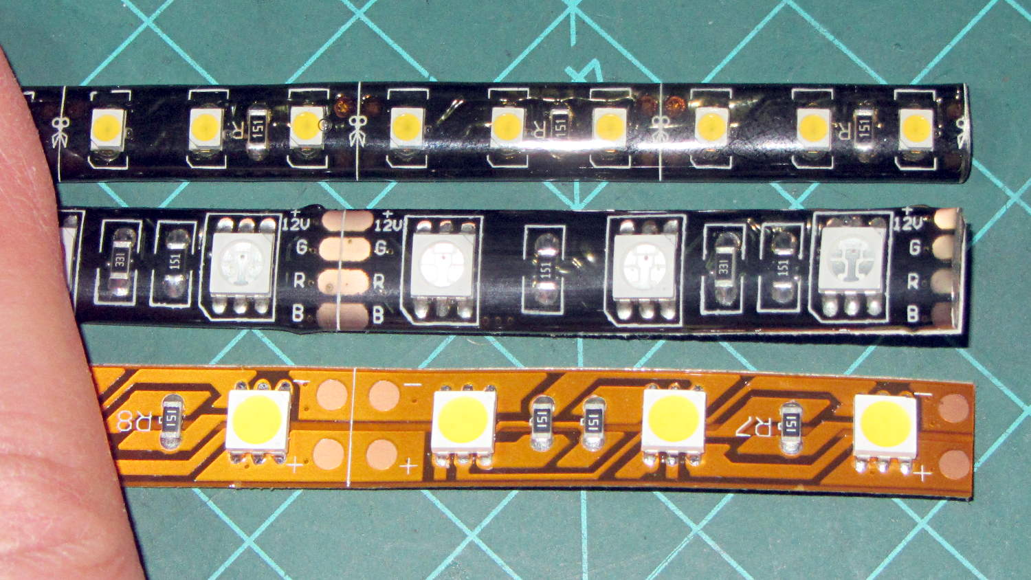
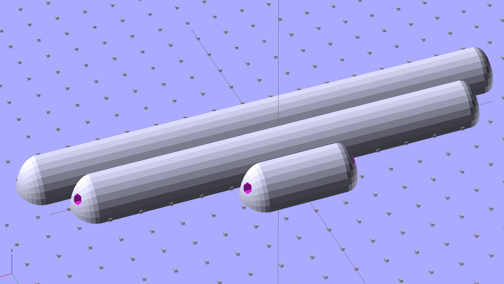
They’re similar to the RGB LEDs from a while ago, with even gummier “waterproof” encapsulation. I got double-density 600 LED strips to put more light emitters across the arm:
Various LED strip lights
The smaller 3528 SMD LEDs (vs. 5050 chips in the others) allow a narrower strip and the double-density layout means each three-LED segment is half as long long. The as-measured dimensions work out to:
25.0 mm segment length
8.2 mm strip width
2.5 mm thickness
The sealant thickness varies considerably, so I’d allow 3.0 mm for that in case it mattered. It slobbers over the edge of the strip here and there; allowing at least 9.0 mm would be wise.
The SMD resistor in each segment is 150 Ω. A 5 segment length drew 85 mA @ 12 V = 17 mA/segment. Boosting the voltage to 12.8 V got the current to the expected 100 mA = 20 mA/segment.
The LEDs are noticeably less bright than the 5050 LEDs, even at 20 mA/segment, but I think they’ll suffice for the task.