Ed Nisley's Blog: Shop notes, electronics, firmware, machinery, 3D printing, laser cuttery, and curiosities. Contents: 100% human thinking, 0% AI slop.
Tag: Improvements
Making the world a better place, one piece at a time
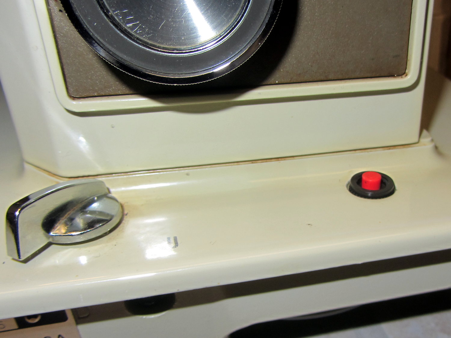
The crash test dummy sewing machine now has a cheerful red momentary pushbutton in the same spot the original machine sported a 120 VAC push-on/push-off power switch:
Kenmore 158 – Digital Power Switch
It’s held in place by a dab of epoxy on the bottom. The threads aren’t quite long enough to engage the ring, so another dab of epoxy holds that in place. In the unlikely event I must replace the button, I’ll deploy a punch and hammer it out from the top; the slick paint on the sides of the straight-sided hole doesn’t provide much griptivity.
The button connects in parallel with the GX270’s front-panel button and the one on the Low Voltage Interface Board, so it operates exactly the same way. My original code didn’t include a delay before turning the power off, which meant that brushing the switch while doing something else would kill the power.
This is not to be tolerated…
You (well, I) must now hold the button down for one second to turn the power off. Releasing it before the deadline has no effect, other than blinking the green power LED on the front panel a few times.
The routine maintains a timer that allows it to yield control to the mainline code, rather than depend on a blocking timer that would screw up anything else that’s in progress:
//------------------
// Handle shutdown timing when power button closes
// Called every time around the main loop

void TestShutdown(void) {

	if (LOW == digitalRead(PIN_BUTTON_SENSE)) {			// power button pressed?
		if (ShutdownPending) {
			if (1000ul < (millis() - ShutdownPending)) {
				printf("Power going off!\r\n");
				digitalWrite(PIN_ENABLE_AC,LOW);
				digitalWrite(PIN_ENABLE_ATX,LOW);
				while(true) {
					delay(20);
					TogglePin(PIN_PWR_G);				// show we have shut down
				}
			}
		}
		else {
			ShutdownPending = millis();					// record button press time
			printf("Shutdown pending...\r\n");
		}
	}
	else {
		if (ShutdownPending) {
			ShutdownPending = 0ul;						// glitch or button released
			printf("Shutdown cancelled\r\n");
		}
	}
}
The normal Arduino bootloader imposes a similar delay while turning the power on, which means that you can’t accidentally light the machine up by bumping the switch. All in all, it’s much more user-friendly this way.
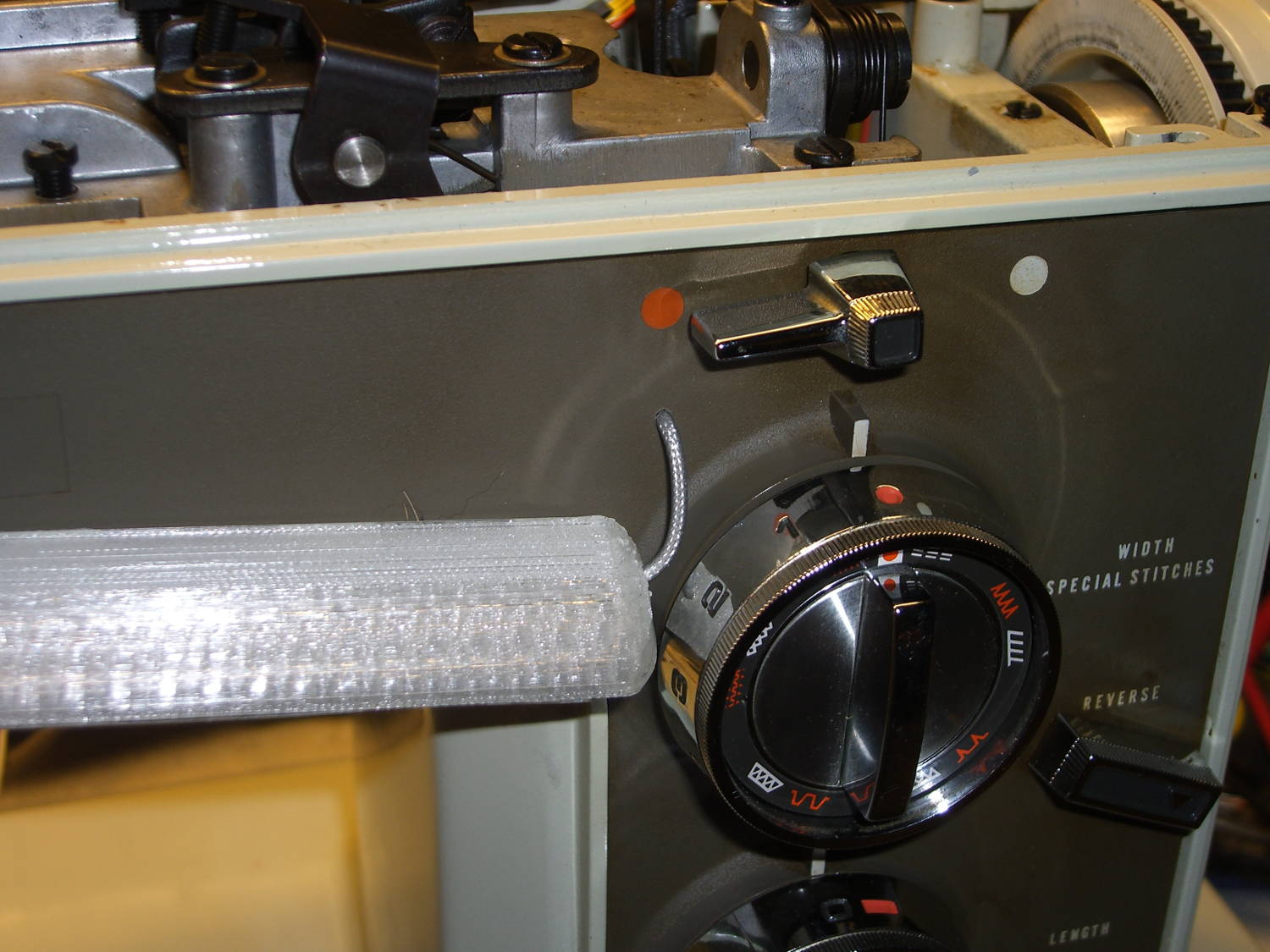
It Has Been Decided (in that place where what is decided must be) to allow a single hole in the sewing machine’s front panel:
Kenmore 158 – Front LED strip – wire routing
The hole barely passes the 2 mm coaxial cable I’m misusing for the LED strips and is located where it:
Clears the machine’s metal frame to the upper left
Isn’t blocked by the knob’s mounting bracket to the lower right
Doesn’t snag the knob’s cam followers all over the insides
Lines up directly below the orange dot for pretty
The first three of those happen behind the front panel, inside the frame, where you (well, I) can neither see nor measure the locations. I used a large outside caliper to get a feel for where the hole could possibly fit, then got it right on the first try!
On the rear panel, it turns out that the presser foot lever doesn’t quite touch the top of its slot in the frame, so the cable for those LED strips can sneak through:
Kenmore 158 – Rear LED strips – wire routing
Just inside that slot, the cable turns right, passes into the endcap, then goes upward to re-emerge at the top, inside the channel used for the old 120 VAC zip cord that powered the incandescent bulb in the endcap.
I had some square cable clips lying around, so I used them, but the (yet to be designed) round versions will look better.
The grody frame tells you this is the crash test dummy machine I’m using to verify things before installing them in Mary’s machine.
The improved cable routing required different hole positions in the LED strip mounts:
Strip Light Mount – Drilled cable routing
The internal wire route follows the original 120 VAC zip cord’s route from the bottom of the machine to the endcap (on the left), with the new branch for the front LEDs curving over the main shaft:
Kenmore 158 – LED strips – internal wire routing
The four-conductor ribbon cable also carries the supply voltage for the yet-to-be-built high intensity LED emitters in the end cap that will replace the 10 mm LEDs, with the ends terminated under the clamp in the middle. Those old steel wire clamps seem grossly oversized for the job, but that’s OK with me.
The ribbon cable eases past that whirling crank arm, then passes through the frame to the outside cover under the handwheel, where it just barely clears the drive belts. A few zip ties hold it out of the way.
The OpenSCAD source code offsets the wiring holes by 0.5 mm from the ends of the LED strips for easier wire bending, but is otherwise pretty much the same as before:
// LED Strip Lighting Brackets for Kenmore Model 158 Sewing Machine
// Ed Nisley - KE4ZNU - March 2014
//  October 2014 - tweak endcap length & channel position

Layout = "Build";			// Build Show Channels Strip

//- Extrusion parameters must match reality!
//  Print with 2 shells and 3 solid layers

ThreadThick = 0.20;
ThreadWidth = 0.40;

HoleWindage = 0.2;			// extra clearance

Protrusion = 0.1;			// make holes end cleanly

AlignPinOD = 1.70;			// assembly alignment pins: filament dia

inch = 25.4;

function IntegerMultiple(Size,Unit) = Unit * ceil(Size / Unit);

//----------------------
// Dimensions

LEDSegment = [25.0,10.0,3.0];		//  size of each LED segment
SEGLENGTH = 0;
SEGWIDTH = 1;
SEGHEIGHT = 2;

WireChannel = 3.0;				// wire routing channel diameter

StripHeight = 12.0;				// sticky tape width

DefaultLayout = [1,2,"Wire","NoWire"];
NUMSEGS = 0;
NUMSTRIPS = 1;
WIRELEFT = 2;
WIRERIGHT = 3;

EndCapSides = 8*4;				// endcap smoothness
EndCapShim = 0.5;				// additional space for easier wire bending

function EndCapSize(Layout) = [(2*WireChannel + EndCapShim),Layout[NUMSTRIPS]*LEDSegment[SEGWIDTH],StripHeight];

//----------------------
// Useful routines

module PolyCyl(Dia,Height,ForceSides=0) {			// based on nophead's polyholes

  Sides = (ForceSides != 0) ? ForceSides : (ceil(Dia) + 2);

  FixDia = Dia / cos(180/Sides);

  cylinder(r=(FixDia + HoleWindage)/2,
           h=Height,
           $fn=Sides);
}

module ShowPegGrid(Space = 10.0,Size = 1.0) {

  RangeX = floor(100 / Space);
  RangeY = floor(125 / Space);

	for (x=[-RangeX:RangeX])
	  for (y=[-RangeY:RangeY])
		translate([x*Space,y*Space,Size/2])
		  %cube(Size,center=true);

}

//-- The negative space used to thread wires into the endcap

module MakeWireChannel(Layout = DefaultLayout,Which = "Left") {

	EndCap = EndCapSize(Layout);	// radii of end cap spheroid

	HalfSpace = EndCap[0] * ((Which == "Left") ? 1 : -1);

	render(convexity=2)
	translate([0,LEDSegment[SEGWIDTH]/2,0])
		intersection() {
			union() {
				cube([2*WireChannel,WireChannel,EndCap[2]],center=true);
				translate([-2*EndCap[0],0,EndCap[2]/2])
					rotate([0,90,0]) rotate(180/6)
						PolyCyl(WireChannel,4*EndCap[0],6);
			}
			translate([HalfSpace,0,(EndCap[2] - Protrusion)]) {
				cube(2*EndCap,center=true);
			}
		}
}

//-- The whole strip, minus wiring channels

module MakeStrip(Layout = DefaultLayout) {

	EndCap = EndCapSize(Layout);	// radii of end cap spheroid

	BarLength = Layout[NUMSEGS] * LEDSegment[SEGLENGTH];				// central bar length

	echo(str("Strip OAL: ",BarLength + 2*EndCap[SEGLENGTH]));

	hull()
		difference() {
			for (x = [-1,1])						// endcaps as spheroids
				translate([x*BarLength/2,0,0])
					resize(2*EndCap) rotate([0,90,0]) sphere(1.0,$fn=EndCapSides);
			translate([0,0,-EndCap[2]])
				cube([2*BarLength,3*EndCap[1],2*EndCap[2]],center=true);
			translate([0,-EndCap[1],0])
				cube([2*BarLength,2*EndCap[1],3*EndCap[2]],center=true);
		}

}

//-- Cut wiring channels out of strip

module MakeMount(Layout = DefaultLayout) {

	BarLength = Layout[NUMSEGS] * LEDSegment[SEGLENGTH];

	difference() {
		MakeStrip(Layout);
		if (Layout[WIRELEFT] == "Wire")
			translate([(BarLength/2 + EndCapShim),0,0])
				MakeWireChannel(Layout,"Left");
		if (Layout[WIRERIGHT] == "Wire")
			translate([-(BarLength/2 + EndCapShim),0,0])
				MakeWireChannel(Layout,"Right");
	}
}

//- Build it

ShowPegGrid();

if (Layout == "Channels") {
	translate([ (2*WireChannel + 1.0),0,0]) MakeWireChannel(DefaultLayout,"Left");
	translate([-(2*WireChannel + 1.0),0,0]) MakeWireChannel(DefaultLayout,"Right");
}

if (Layout == "Strip") {
	MakeStrip(DefaultLayout);
}

if (Layout == "Show") {
	MakeMount(DefaultLayout);
}

if (Layout == "Build") {

	if (false) {					// original no-drill wiring
		translate([0,(3*LEDSegment[SEGWIDTH]),0]) MakeMount([1,2,"Wire","Wire"]);		// rear left side, vertical
		translate([0,0,0]) MakeMount([5,2,"Wire","NoWire"]);				// rear top, across arm
		translate([0,-(3*LEDSegment[SEGWIDTH]),0]) MakeMount([6,2,"NoWire","Wire"]);	// front top, across arm
	}

	if (true) {						// front: drill panel, rear: route through foot lift lever
		translate([0,(3*LEDSegment[SEGWIDTH]),0])
			MakeMount([1,2,"NoWire","Wire"]);				// rear left side, vertical
		translate([0,0,0])
			MakeMount([5,2,"Wire","Wire"]);					// rear top, across arm
		translate([0,-(1*LEDSegment[SEGWIDTH]),0])
			rotate(180)
			MakeMount([6,2,"NoWire","Wire"]);				// front top, across arm
	}
}
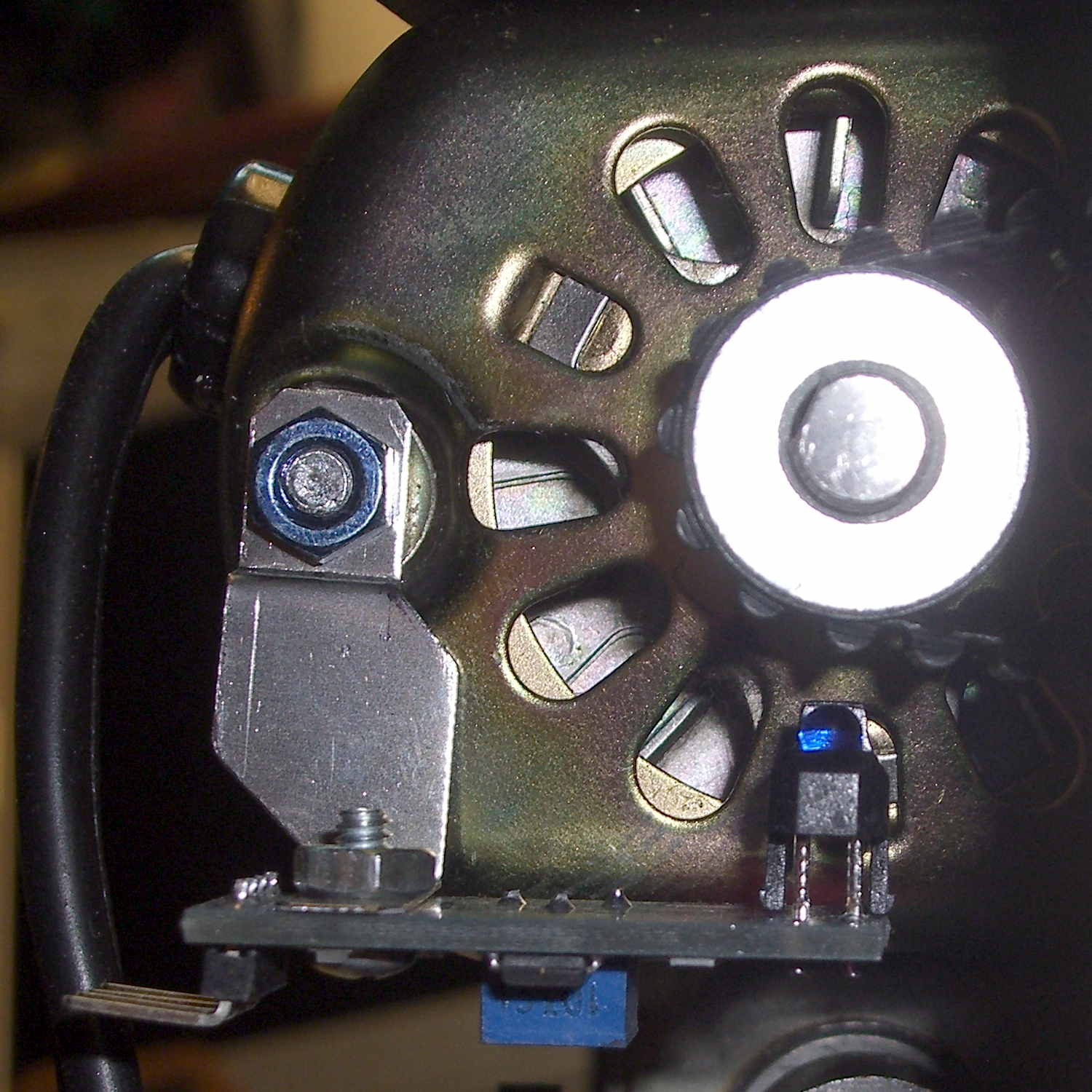
The first sensor bracket came from the scrap pile, but showed that it would produce 1/rev pulses from the motor shaft pulley. The positioning wasn’t quite right, so I made another bracket that put the TCRT5000 sensor at right angles to the pulley:
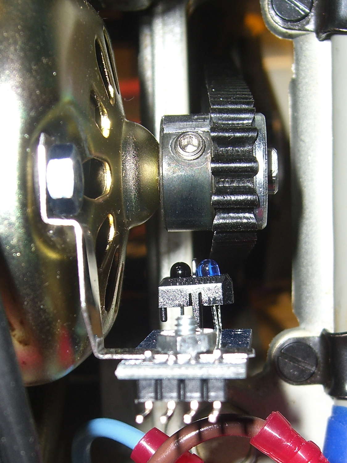
TCTR5000 Motor RPM Sensor – end view
All of the sensors have a rakish tilt over their PCB, so at some point I must resolder them:
TCTR5000 Motor RPM Sensor – side view
It might not matter, as the phototransistor on the left peers directly at the pulley, with the LED on the right acting as a floodlight.
“Made another bracket” sounds like the metal sprang fully formed from the concept. Herewith, the early contestants atop a sketch and the flat layout for The Ultimate Bracket:
Motor RPM Sensor Brackets
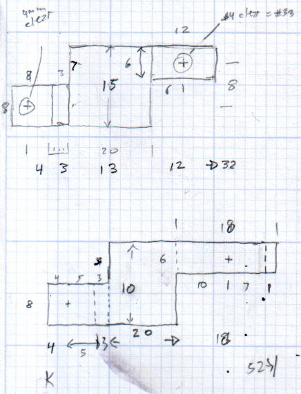
A closer look at that final dimension sketch, because I’ll need it again:
RPM Bracket Dimensions
The vertical size of the center section (12 mm) sets the perpendicular distance of the sensor from the shaft. The horizontal size (14 mm) controls the pulley-to-sensor spacing.
The horizontal distance from the center section to the hole on the right (10 mm) adjusts the sensor spacing parallel to the shaft.
I cut the overall rectangle with tin snips, drilled & cleaned the holes, applied a nibbling tool to the details, trimmed the corners, filed off sharp edges & spines, and it was all good.
The doodles for the first few attempts, as I don’t want to repeat those mistakes:
Bracket Doodles
All in all, a few more hours of Quality Shop Time than I expected…
At some point I got two strap wrenches with rubber straps. No reinforcements, just pure rubber or neoprene or whatever. I’d cinch up on something, apply some torque, and the straps would stretch beyond belief. I’d always wanted to replace the straps and, finally, when I had the shop replace the van’s belts, I asked for a timing(*) belt from their scrap can.
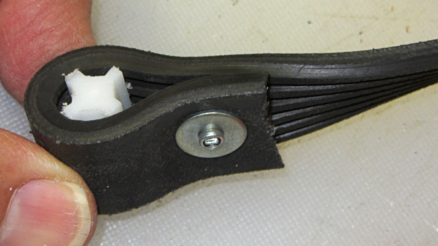
The smaller wrench required slitting the belt lengthwise and discarding two ribs. A pop rivet attaches two small chunks of the belt to form a block; the original belt had a molded-in triangular end:
Strap Wrench timing belt refit – small
The larger belt required a plastic filler, cut from something that might once have been a flag holder, riveted into a loop that firmly jams inside the wrench handle:
Strap Wrench timing belt refit – large
Nothing fancy, but strap wrenches work much better when the straps don’t stretch!
Found these pix while I was looking for something else…
(*) As Dan points out in the comments, this is a serpentine belt. I got it while the shop replaced the Sienna’s timing belt; that’s my story and I’m sticking with it…
For whatever reason, the handle of the ceramic knife extended a few millimeters below the blade heel:
Farberware ceramic knife
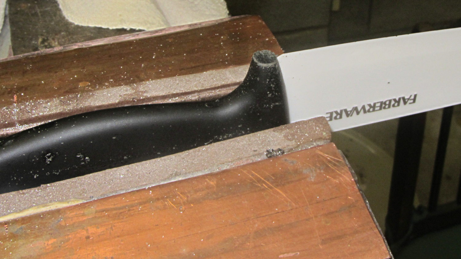
Now it doesn’t:
Farberware ceramic knife – trimmed handle
Which makes it much more usable for the kind of chopping I do around here: the blade hits the cutting board squarely, producing chunks of veggies along its entire length.
A coarse file removed most of the stub, followed with a fine file and a little sandpaper action to round the edges.
Amazingly enough, none of that fussing around touched the blade, nor did I gash myself!
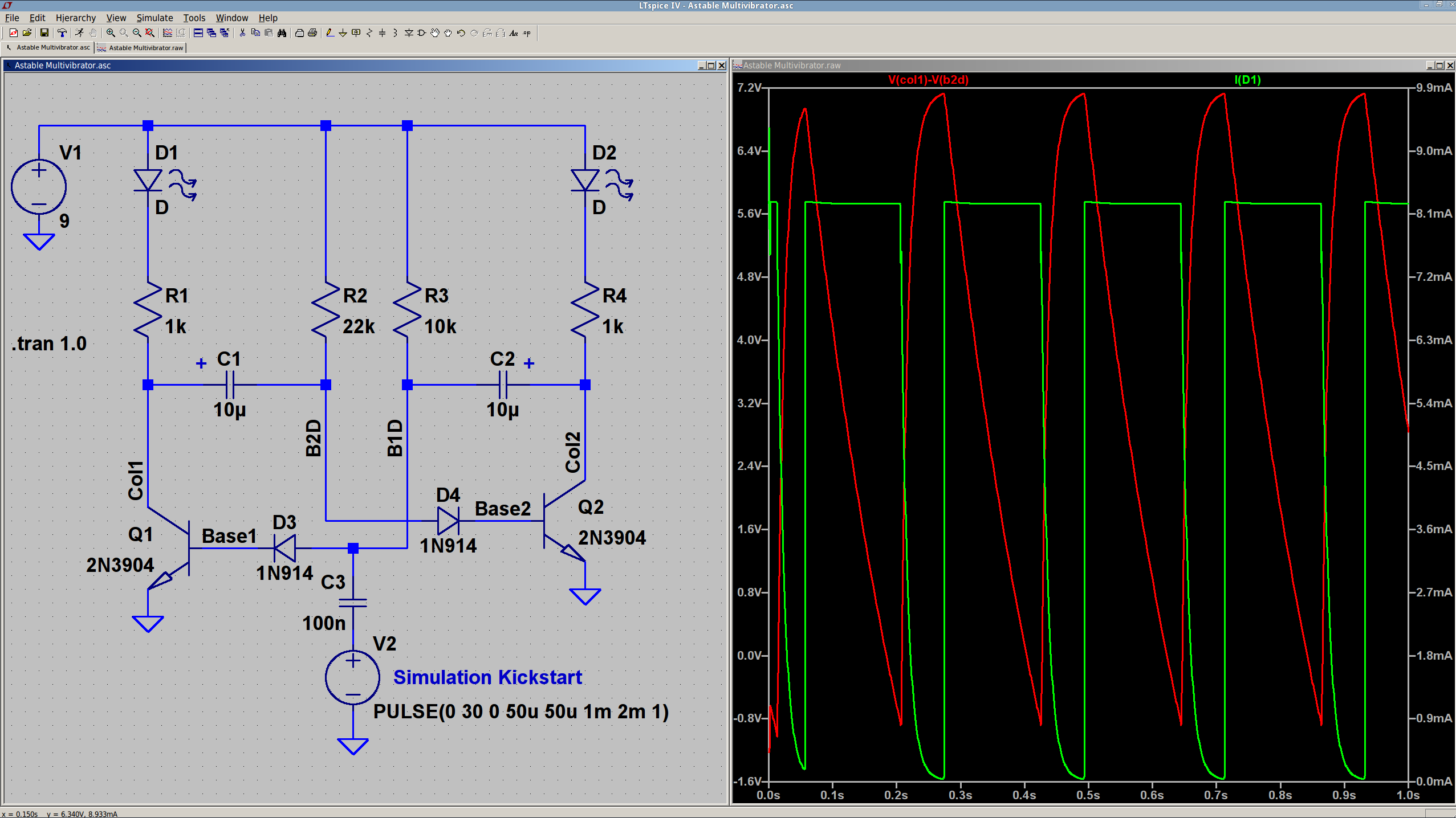
The 10 µF caps scale the output to visible blinkiness. Their polarity may seem backwards, but the red trace in the simulation shows that the net voltage is positive in that direction for nearly the entire cycle. They see only two forward biased junctions in the other direction, so they shouldn’t blow up.
I built it with resistors from the SqWr junk box parts cabinet that were close to the nominal values.
Connecting the transistor base / cap charging resistors to the power supply, rather than the LEDs, gets rid of the tiny current when the LEDs should be off.
The cap-and-pulse-generator dingus on the bottom kickstarts the simulation; it doesn’t have any physical significance.
Memo to Self: Build one with a pair of ET227 transistors and some 100 W tungsten bulbs…
Commercial LED strip lights for sewing machines mount their cables with little stick-on anchors and cable ties. I wasn’t happy with the cable tie thing and finally figured this out:
Kenmore 158 – LED strip light cable clips
The clips have that size & shape because they fit exactly atop some pre-cut foam squares from the Tape Lookaside Buffer:
LED strip light cable clips
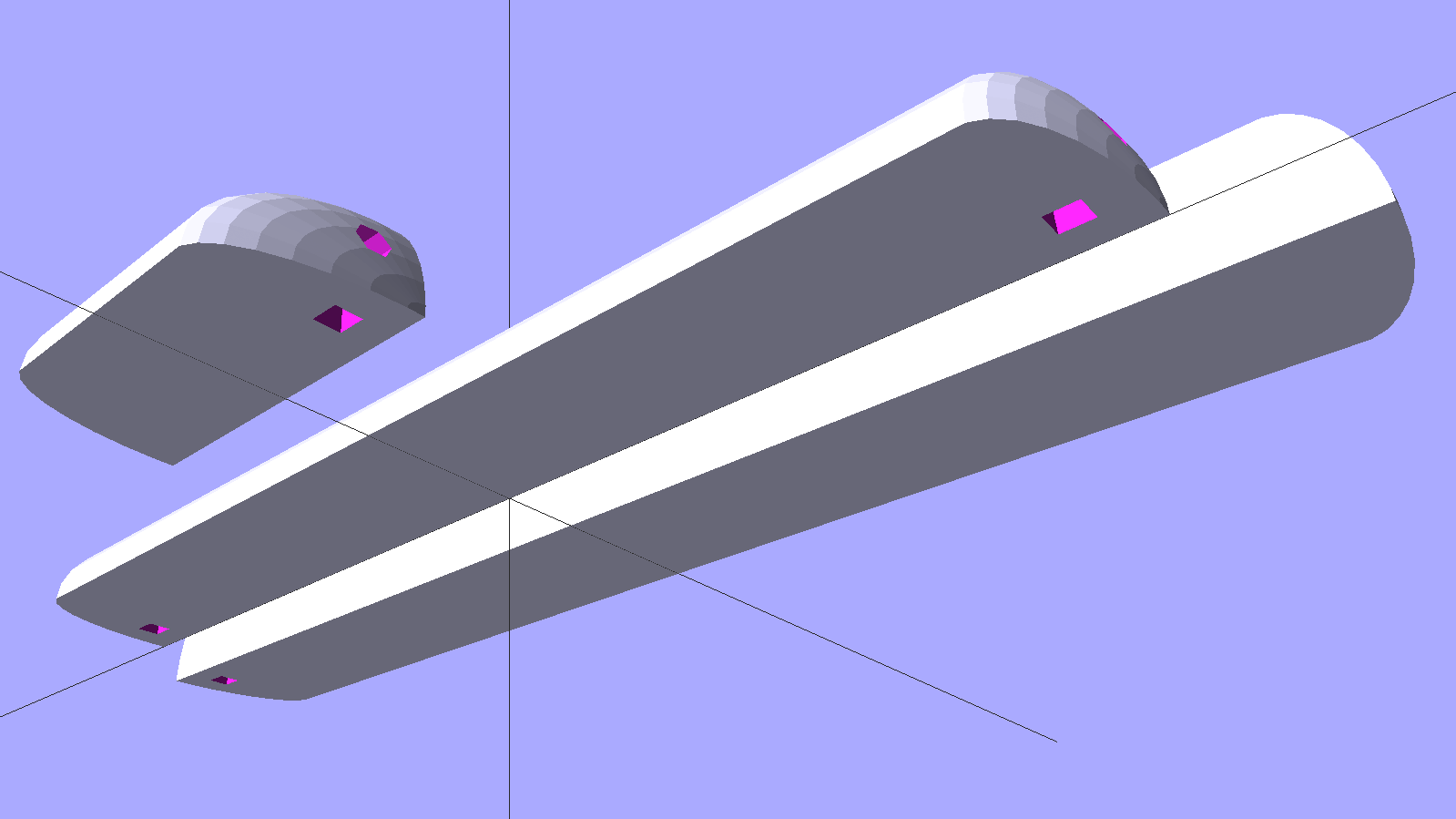
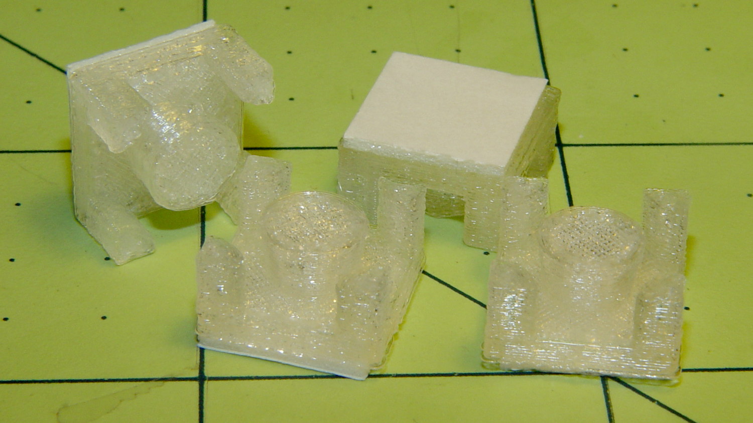
You can see the shape better in the solid model:
LED Cable Clips
The central bollard has a slight taper to retain the cable, the quarter-posts are straight, and they’re both twice the cable diameter tall. The clearance between the center and corner posts at the top matches the cable diameter, so there’s a bit of bending room at the bottom, and, with the cable bent around the center, it won’t fall out on its own.
The cute coaxial cable I’m misusing for the LED strips measures just shy of 2 mm, making these into little bitty things. The corner posts seem surprisingly strong, despite 3D printing’s reputation for crappy quality; I haven’t been able to break one off with more effort than seemed warranted.
The OpenSCAD source code:
// LED Cable Clips
// Ed Nisley - KE4ZNU - October 2014

//- Extrusion parameters must match reality!

ThreadThick = 0.20;
ThreadWidth = 0.40;

HoleWindage = 0.2;			// extra clearance

Protrusion = 0.1;			// make holes end cleanly

AlignPinOD = 1.70;			// assembly alignment pins: filament dia

function IntegerMultiple(Size,Unit) = Unit * ceil(Size / Unit);

//----------------------
// Dimensions

Base = [12.0,12.0,IntegerMultiple(2.0,ThreadThick)];	// base over sticky square

CableOD = 2.0;

BendRadius = 3.0;

Bollard = [BendRadius,(sqrt(2)*Base[0]/2 - CableOD - BendRadius),2*CableOD];
B_BOT = 0;
B_TOP = 1;
B_LEN = 2;

NumSides = 5*4;

//----------------------
// Useful routines

module PolyCyl(Dia,Height,ForceSides=0) {			// based on nophead's polyholes

  Sides = (ForceSides != 0) ? ForceSides : (ceil(Dia) + 2);

  FixDia = Dia / cos(180/Sides);

  cylinder(r=(FixDia + HoleWindage)/2,
           h=Height,
           $fn=Sides);
}

module ShowPegGrid(Space = 10.0,Size = 1.0) {

  RangeX = floor(100 / Space);
  RangeY = floor(125 / Space);

	for (x=[-RangeX:RangeX])
	  for (y=[-RangeY:RangeY])
		translate([x*Space,y*Space,Size/2])
		  %cube(Size,center=true);

}

//----------------------
// Build it

ShowPegGrid();

intersection() {
	translate([0,0,(Base[2] + Bollard[2])/2])			// overall XYZ outline
		cube(Base + [0,0,Bollard[2]],center=true);

	union() {
		translate([0,0,Base[2]/2])						// oversize mount base
			scale([2,2,1])
				cube(Base,center=true);

		for (i=[-1,1] , j=[-1,1]) {						// corner bollards
			translate([i*Base[0]/2,j*Base[1]/2,(Base[2] - Protrusion)])
				rotate(180/NumSides)
				cylinder(r=Bollard[B_BOT],h=(Bollard[B_LEN] + Protrusion),center=false,$fn=NumSides);

		translate([0,0,(Base[2] - Protrusion)])			// center tapered bollard
			cylinder(r1=Bollard[B_BOT],r2=Bollard[B_TOP],h=(Bollard[B_LEN] + Protrusion),center=false,$fn=NumSides);
		}
	}
}
Now that I think of it, maybe a round clip would look nicer. The central bollard would stay, but the circular outside rim could have three cutouts. When these fall off, I’ll give that a try.
They may be square and clunky, but they look much better than Gorilla Tape…