Ed Nisley's Blog: Shop notes, electronics, firmware, machinery, 3D printing, laser cuttery, and curiosities. Contents: 100% human thinking, 0% AI slop.
Tag: Improvements
Making the world a better place, one piece at a time
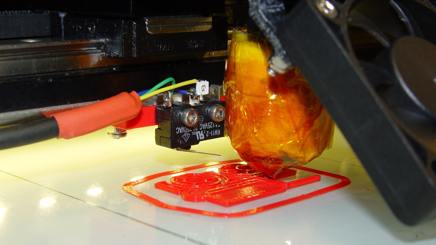
Mounting the Z-axis platform switch on the X gantry to sense the actual platform position worked perfectly with the original MakerGear V3 hot end, at least after I relocated the switch a bit further from the balance point. It does require moving the nozzle off the platform before homing the Z axis, for the obvious reason:
M2 Z-min switch – center gantry – in action
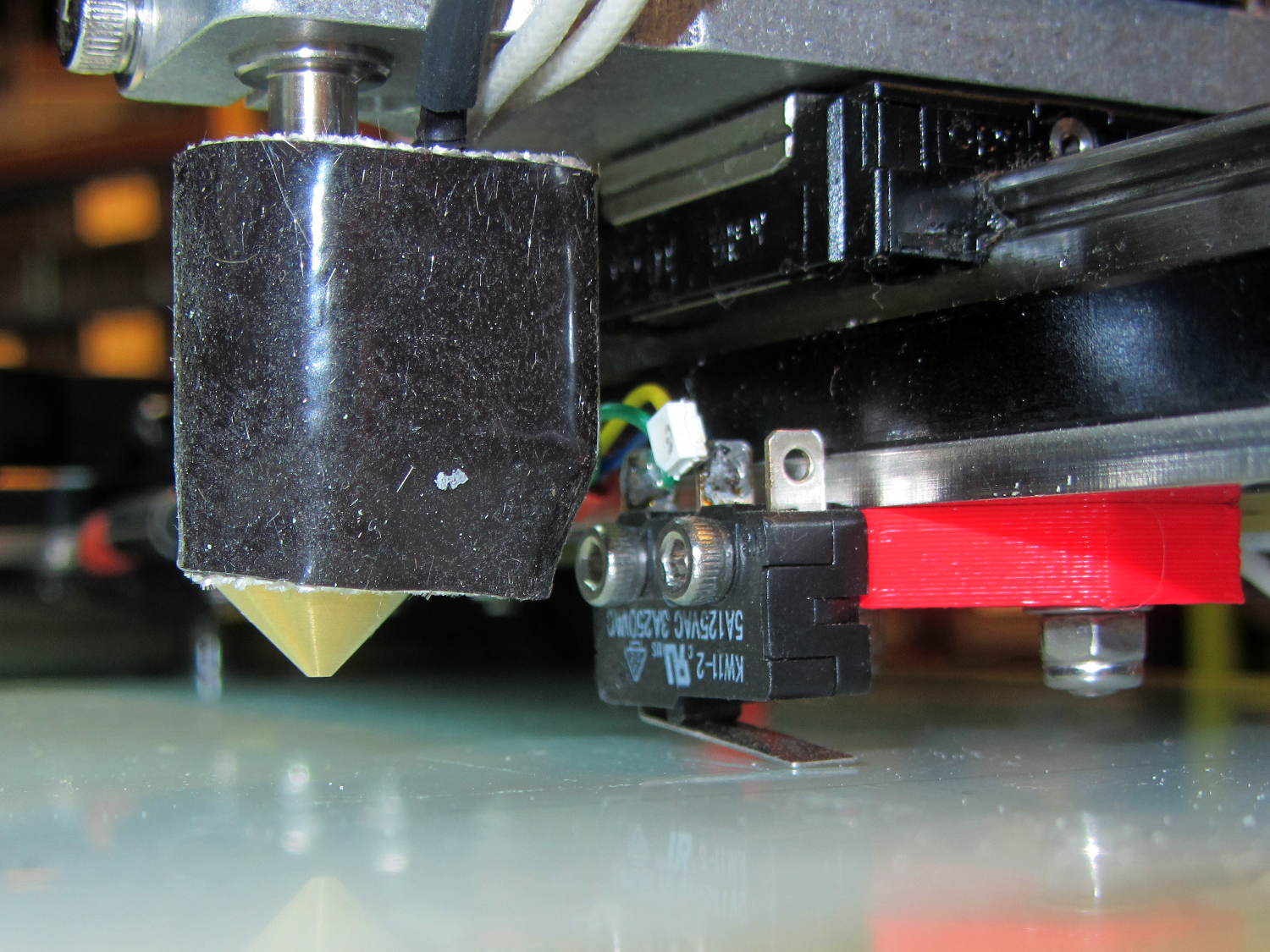
The smaller MakerGear V4 hot end uses a completely different mount that puts the nozzle higher than the switch lever:
M2 V4 hot end vs platform Z switch
The clearances were close enough to rule out plastic, so I bandsawed some 33 mil (1/32 inch) brass shim stock and drilled holes in the appropriate spots:
Brass switch bracket – drilling
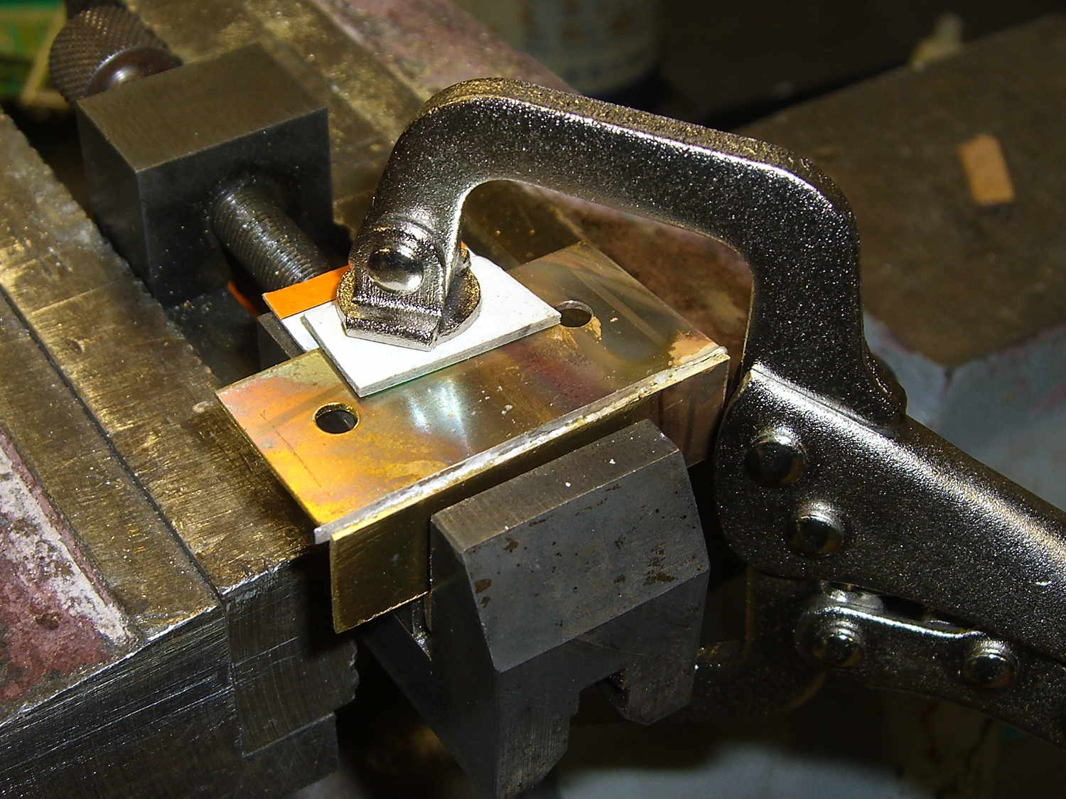
After discovering the blindingly obvious fact that you can’t heat brass sheets clamped to a steel vise enough to melt silver solder, I padded the brass with cardboard insulation and tried again:
Brass switch bracket – clamped for soldering
The cardboard charred and burned and stank up the shop, but held everything in alignment long enough:
Brass switch bracket – soldered
A bit of file & sandpaper work shined it up just fine, then I slotted the lower mounting holes enough to accommodate 2-56 nuts between the gantry and the bracket:
Brass switch bracket – mounted – front view
Yeah, I could tap 2-56 holes into the brass sheet, but let’s be reasonable: two turns does not a secure fitting make.
Here’s why a plastic bracket wouldn’t work:
Brass switch bracket – side view
That’s with the V4 hot end aligned per instructions, although I may rotate it 1/4 turn clockwise at some point. Note that there’s no filament going in the top, as I did all this before firing that devil up for the first time.
The switch lever had enough free travel that the platform would hit the bottom of the X axis linear slide screws before activating the switch, but lowering the switch would put the lever below the nozzle. I added a 15 mil brass shim to the lever and it’s all good:
Brass switch bracket – lever shim detail
Admittedly, the lever rests a bit less than 1.000 mm above the nozzle, but we’ll see how much trouble that causes.
The switch trips 2.0 mm above the nozzle, so the new startup G-Code looks like this:
;-- Slic3r Start G-Code for M2 starts --
;  Ed Nisley KE4NZU - 2015-03-01
;  Makergear V4 hot end
; Z-min switch at platform, must move nozzle to X=135 to clear
M140 S[first_layer_bed_temperature]	; start bed heating
G90				; absolute coordinates
G21				; millimeters
M83				; relative extrusion distance
G92 Z0			; set Z to zero, wherever it might be now
G1 Z10 F1000	; move platform downward to clear nozzle; may crash at bottom
G28 Y0			; home Y to clear plate, origin in middle
G92 Y-127
G28 X0			; home X, origin in middle
G92 X-100
G1 X130 Y0 F30000	; move off platform to right side, center Y
G28 Z0			; home Z to platform switch, with measured offset
G92 Z-2.00
G0 Z2.0			; get air under switch
G0 Y-127 F10000	; set up for priming, zig around corner
G0 X0			;  center X
G0 Y-125.0		; just over platform edge
G0 Z0 F500	; exactly at platform
M109 S[first_layer_temperature]	; set extruder temperature and wait
M190 S[first_layer_bed_temperature]	; wait for bed to finish heating
G1 E20 F300		; prime to get pressure, generate blob on edge
G0 Y-123		; shear off blob
G1 X15 F20000	; jerk away from blob, move over surface
G4 P500			; pause to attach
G1 X45 F500		; slowly smear snot to clear nozzle
G1 Z1.0 F2000	; clear bed for travel
;-- Slic3r Start G-Code ends --
The prime-and-wipe section accommodates gooey PETG, although that will require more attention.
A Netgear GS308 gigabit switch replaced an older 100 Mb/s switch below the living room window across from my desk:
Netgear switch mounted
Of course, the mounting slots in the new switch didn’t match those in the old switch. A scrap of plastic sheet serves as a space transformer:
Netgear switch backplate
The odd-looking knife plows a furrow in the plastic, after which you capture the sheet between two flat surfaces and snap it along the scribe. Faster / easier / more accurate / less exciting than bandsawing, cleans up with quick swipes from an edge deburring tool, not much can go wrong.
The top holes are 3/16 inch for the existing mounting screws. The center holes are tapped 6-32 with nuts to hold them in place.
A block of closed-cell foam behind the sheet holds it vertical so I can just barely see the activity LEDs at each port from my desk.
Yes, I scrubbed the sheet before mounting it…
Memo to Self: put the screw holes slightly higher, so they’re properly centered after sliding the case into position. Otherwise, you must cut another slice off the top of the sheet before mounting it.
For whatever reason, the audio books we get at the library sale generally don’t have CDDB database entries, so I fill in the appropriate values by hand. Weirdly, some individual CDs within a single book do have entries, which confuses the process (well, me) no end unless I notice it first; I’ve turned off auto-lookup to make that problem Go Away. Perhaps a different database would help, but I don’t do this nearly often enough to care that much.
Given that:
Mary plays the tracks sequentially from start to finish
The tracks don’t correspond to book divisions
She doesn’t care about the details
I concluded a simple track naming convention that sorts in ascending alphabetic order would suffice.
Asunder auto-fills the fields after the first CD. After a bit of manual wrestling to extract an error-filled track, I had a directory full of MP3 files with informative, albeit slightly redundant, names:
1901-01 - Track 01.mp3
Alas, the ID3 fields apply to a single music CD, with track numbers and names within a single album and no notion of a multi-CD set. I use the “year” field as a CD sequence number; it must be a four-digit year and, seeing as how Asunder defaults to 1900, the first CD becomes 1901.
So the following fields apply:
Genre: “Audio Book” (for v2 tags) or Speech (v1 tag = 101)
Artist: author
Album: book title
Year: 19 + CD number within set as 1901
Track Name = CD number + track number as “D:01 T:01”
But the real gotcha is that the Most Favorite MP3 Player (remember MP3 players?) recognizes only ID3 v1 tags and Asunder writes only ID3 v2 tags.
Fortunately, the id3v2 utility can do this thing. Rather than screw around selecting each file, extracting the v2 tags, doing something horrible involving bash or sed or awk or whatever, and ramming the results into v1 tags, I just fed in the appropriate number of CDs and more than enough tracks, then ignored any errors concerning missing files.
Firing a Bash cannon broadside:
for d in {01..15} ; do id3v2 -1 -a "Who Wrote It" -A "The Book Title" -y 19$d -g Speech 19${d}* ; done
for d in {01..15} ; do for t in {01..15} ; do id3v2 -1 -t "D:${d} T:$t" -T $t 19${d}-${t}* ; done ; done
for d in {01..15} ; do for t in {01..15} ; do id3v2 -2 -t "D:${d} T:$t" -T $t 19${d}-${t}* ; done ; done
The last line tightens up the title name tag in v2 format to fit the MP3 player’s teeny display. The next time around, I should remove the “Track” text from the file name for consistency.
Part of the flailing about while working around the Ubuntu video driver update glitch included blindly swapping a Displayport cable, which triggered another failure after everything settled down: the (empty) DVD drive’s activity light remained dimly lit with the PC off and both monitors in power-save mode. Unplugging the PC’s power cord extinguished all the internal LEDs on the system board, but left the drive light shining the same dim green. Disconnecting the USB cables to the monitors (they both have USB hubs) had no effect. Unplugging the monitors extinguished the LED after a bit. Unplugging one of the Displayport cables turned it off instantly, which was a clue that took a while to recognize.
Worse, the landscape monitor, a year-old Dell U2711, now refused to wake up from power-save mode during boot, even when it was the only monitor connected to the PC. Searching with an assortment of relevant keywords produced severalinterestingresults, including a lengthy Dell support forum thread, all suggesting a deeper and surprisingly longstanding problem with Displayport connections on big Dell monitors.
I knew most of the remedies weren’t relevant, because this failure happened while the BIOS felt around to identify the monitors: not a driver issue (not in effect yet), not a Windows issue (fer shure!), not a Linux issue, and not a BIOS configuration issue (nothing changed, plus Dell doesn’t allow much configuration).
It turns out that the original pair of Displayport cables bore Amphenol logos on the connector shells and cable. One of the replacements was a Genuine eBay cable from halfway around the planet, bearing no markings of any sort. Given the hints in those search hits, I discovered that the Amphenol-branded cables did not carry pin 20 between the connectors, but the eBay cables did: just a little something extra from eBay!
Installing the two Amphenol cables extinguished the DVD drive light by preventing the monitor standby power from backfeeding the PC through the video card and the monitor woke up correctly on the next two boots. Whether that will permanently cure the startup problem remains to be seen, as it was somewhat intermittent with the wrong cable and the forum threads suggest that the monitor will continue to work for a while before failing again.
While pondering all that, I severed the pin 20 connection in one of the eBay cables, just to have a different cable in hand. This diagram from the Wikipedia article, with pin 20 highlighted, shows it sitting under the longer blank section above one of the keys:
DisplayPort Connector – pin 20 highlight
The connector shell has snap latches that succumb to gentle prying with a razor knife, revealing the hot-melt-glue potted interior, with the orange wire snaking away from pin 20 at the top of the other side:
DP connector – latch side
One snip, a bit of prying to extract the end from the glue, and it’s ready to be buttoned up again:
DP connector – pin 20 wire cut
Both Amphenol cables and the modified eBay cable now have labels noting that they do not connect pin 20. We’ll see if that makes any difference…
case PD_RUN :
	if (PedalPosition > 5) {
		if (MotorDrive.State != RUNNING) {
			EnableMotor();
			MotorDrive.State = RUNNING;
		}

		BaseDAC.setVoltage(0x0fff,false);								// give it a solid pulse
		SampleCurrent(PIN_CURRENT_SENSE);								// sample over a half cycle
		if (DriveOnTime > CurrentSamplingTime) {
			delay(DriveOnTime - CurrentSamplingTime);
		}

// Pedal to the metal?
//   ... if so, stall here with motor drive fully on until the pedal releases

		while ((MotorDrive.SpeedRange == SPEED_HIGH) && (PedalPosition >= 100)) {
			PedalPosition = PedalPercent(ReadAI(PIN_PEDAL));
		}

		BaseDAC.setVoltage(0,false);									//  ... then turn it off

		delay(map(constrain(PedalPosition,0,PedalMaxClamp),
				0,100,
				DriveOffTime,0));
	}
	else {
		if (MotorDrive.State == RUNNING) {
			if (MotorSensor.RPM) {
				printf("Coast: %d\r\n",MotorSensor.RPM);
				delay(100);
			}
			else {
				printf("Parking ");
				ParkNeedle(MotorDrive.ParkPosition);
				MotorDrive.State = STOPPED;
				printf(" stopped\r\n");
			}
		}
	}
	break;
The magic happens in highlighted statement, which flips the sense of the pedal motion and linearly scales the result into a delay() value ranging from 120 ms (pedal barely pressed) down to 0 ms (pedal almost fully pressed). If the pedal is all the way down, then the preceding while() locks up until it’s released a bit, whereafter the delay will be nearly zero.
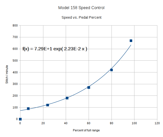
That sorta-kinda worked, but the user community said that the pedal response required pushing too hard for top speed: it should get faster, sooner. The problem came from the simplistic way I set the speed: it was inversely proportional to the position.
Plotting speed against pedal position shows the problem:
Speed vs pedal – period control
I figured the right approach was to make the speed vary linearly with the pedal position, so the trick was to plot the off-time delay vs. the actual speed:
Off-time delay vs speed – period control
The second-order equation bottles up a bunch of nonlinear things. Given that this was using the original code, I made the dubious assumption that more-or-less the same delay in the new code would produce more-or-less the same speed.
The new code discards the current-sampling routine that I was using to get a fixed delay (because I don’t need to know the current in pulse-drive mode), then used that time for the floating-point calculation required to find the off-time delay. That chunk of code took a bit of fiddling to get right:
case PD_RUN :
	if (PedalPosition > 5) {
		if (MotorDrive.State != RUNNING) {
			EnableMotor();
			MotorDrive.State = RUNNING;
		}

		BaseDAC.setVoltage(0x0fff,false);								// give it a solid pulse
		MillisOn = millis() + (unsigned long)DriveOnTime;

		TargetSpeed = (float)map(constrain(PedalPosition,0,PedalMaxClamp),
				0,100,
				0,700);						// quick and dirty 0 to 700 stitch/min range
		OffTime = (int)((1.94e-4*TargetSpeed - 0.286)*TargetSpeed + 106.0);
		OffTime = constrain(OffTime,0,120);								// clamp to reasonable range
		MillisOff = MillisOn + (unsigned long)OffTime;					// compute end of off time

		while (millis() <= MillisOn) {									// wait for end of pulse
			continue;
		}

		if ((PedalPosition >= 100) && (MotorDrive.SpeedRange == SPEED_HIGH)) {	// pedal down in full speed mode?
			printf("Full speed ... ");
			OffTime = 0;
			while (PedalPosition >= 100) {								//  ... full throttle!
				PedalPosition = PedalPercent(ReadAI(PIN_PEDAL));
			}
			BaseDAC.setVoltage(0,false);								//  pedal released, start coasting
			printf(" done\r\n");
		}
		else {															// pedal partially pressed
			BaseDAC.setVoltage(0,false);								// pulse done, turn motor off
			while (millis() <= MillisOff) {								// wait for end of off period
				continue;
			}
		}
	}
But the result looks as pretty as you could possibly expect:
Speed vs pedal – linearized speed control
The pedal still provides a soft-start transition from not moving to minimum speed, which remains an absolute requirement: having an abrupt transition to that straight line would be a Bad Thing. Fortunately, the nature of the magnet moving toward the Hall effect sensor gives you that for free.
Although we’re still evaluating the results, the user community seems happier…
Adjusting the output voltage vs. position for the sewing machine’s food pedal quickly revealed that the code shouldn’t depend on the actual ADC values. That’s blindingly obvious in hindsight, of course.
The maximum with the pedal in its overtravel region doesn’t change by much, because the Hall effect sensor output voltage saturates in a high magnetic field. I used a hardcoded word PedalMax = 870; which comes from 4.25 V at the ADC input.
On the low end, the sensor output can change by a few counts depending on small position changes, so I sampled the (presumably released) pedal output during the power-on reset:
	PedalMin = ReadAI(PIN_PEDAL);				// set minimum pedal input value
	printf("Set PedalMin: %u\r\n",PedalMin);
	PedalMaxClamp = 100;						// set upper speed limit
Given the complete ADC range, this function normalizes a value to the range [0,100], conveniently converting the pedal position into a percent of full scale:
int PedalPercent(word RawPos) {
int Clamped;

	Clamped = constrain(RawPos,PedalMin,PedalMax);
	return map(Clamped,PedalMin,PedalMax,0,100);
}
Graphing the normalized values against pedal position would have the same shape as the ADC values. All I’m doing is rescaling the Y axis to match the actual input limits.
The top of the main loop captures the pedal position:
Now, it’s easy to add a slight deadband that ensures the sewing machine doesn’t start when you give the pedal a harsh look; the deadband is now a percent of full travel, rather than a hard-coded ADC count or voltage.
For example, in needle-follows-pedal mode, you must press the pedal by more than 10% to start the stitch, slightly release it to finish the stitch, and then almost completely release it to proceed to the next stitch:
	case PD_FOLLOW:
		if (PedalPosition > 10) {
			printf("Pedal Follow\r\n");
			ParkNeedle(NS_DOWN);
			do {
				PedalPosition = PedalPercent(ReadAI(PIN_PEDAL));
			} while (PedalPosition > 10);
			ParkNeedle(NS_UP);
			do {
				PedalPosition = PedalPercent(ReadAI(PIN_PEDAL));
			} while (PedalPosition > 2);
		}
		break;
Adjusting percentages turns out to be much easier than fiddling with ADC values.