Ed Nisley's Blog: Shop notes, electronics, firmware, machinery, 3D printing, laser cuttery, and curiosities. Contents: 100% human thinking, 0% AI slop.
Tag: Improvements
Making the world a better place, one piece at a time
That lets me position the whole affair to the right of the sewing machine, in what seems to be its natural position, without having the cable form a loop that would push it off the platform. It’s not entirely clear how we’ll keep a straight cable from pulling it off, but that’s in the nature of fine tuning.
Anyhow, rotating the LCD isn’t a big deal, because the Adafruit library does all the heavy lifting:
// LCD orientation: always landscape, 1=USB upper left / 3=USB lower right
#define LCDROTATION 3

... snippage ...
tft.begin();
tft.setRotation(LCDROTATION);	// landscape, 1=USB upper left / 3=USB lower right
Flipping the touch screen coordinates required just interchanging the “to” bounds of the map() functions, with a conditional serving as institutional memory in the not-so-unlikely event I must undo this:
#if LCDROTATION == 1
	p->x = map(t.y, TS_Min.y, TS_Max.y, 0, tft.width());	// rotate & scale to TFT boundaries
	p->y = map(t.x, TS_Min.x, TS_Max.x, tft.height(), 0);	//   ... USB port at upper left
#elif LCDROTATION == 3
	p->x = map(t.y, TS_Min.y, TS_Max.y, tft.width(), 0);	// rotate & scale to TFT boundaries
	p->y = map(t.x, TS_Min.x, TS_Max.x, 0, tft.height());	//   ... USB port at lower right
#endif
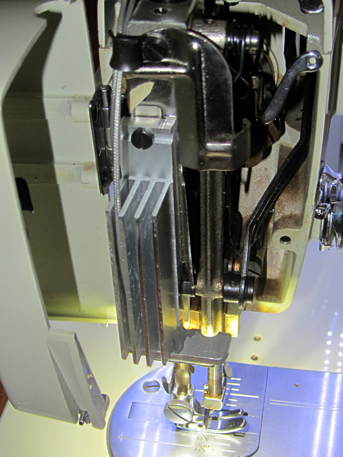
The Kenmore 158 sewing machine crash test dummy has plenty of light:
Kenmore 158 LED Lighting – first light
Well, as long as you don’t mind the clashing color balance. The needle LEDs turned out warmer than I expected, but Mary says she can cope. I should build a set of warm-white LED strips when it’s time to refit her real sewing machine and add another boost supply to drive them at their rated current.
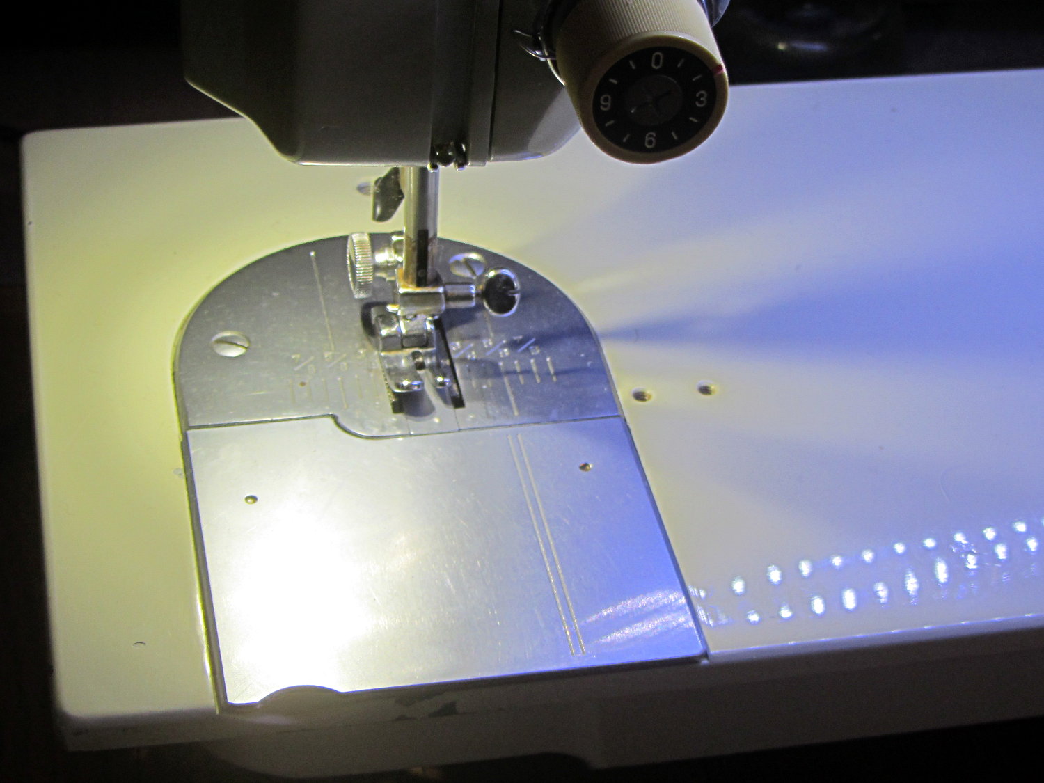
Much to our relief, the two LEDs at the needle don’t cast offensively dark shadows:
A longstanding Xubuntu / XFCE UI problem has been single-pixel window borders that make click-and-drag resizing essentially impossible. The reason it’s a longstanding problem has been the developers’ unflinching response to any and all issues raised on the bug tracker:
I had never looked for the XFCE theme-building documentation (and, thus, never found any), because building a whole new theme would be a lot of work just to resize the damn borders. It should be feasible to tweak only the borders of an existing theme, but … I stalled.
Repeatedly. On every single version of Xubuntu that’s come along.
Fortunately, someone recently did the legwork and summarized the method, which I slightly adapted:
cd /usr/share/themes/
sudo cp -a Greybird-compact/ Greybird-wide
cd Greybird-wide/xfwm4
for f in bottom left right ; do sudo cp ../../Daloa/xfwm4/${f}* . ; done
sudo sed -i -e 's/C0C0C0/CECECE/' *xpm
sudo sed -i -e 's/A0A0FF/7C7C7C/' *xpm
sudo sed -i -e 's/E0E0FF/E0E0E0/' *xpm
The exact color mapping depends on which two themes you’re using. You can also specify GTK element colors, which seems like a better way to do it. Maybe next time.
Apparently, the corresponding PNG files contain transparency information for the XPM files, but I haven’t bothered to investigate how that works or what might happen if I tweaked them.
Then you select the new Graybird-wide theme and It Just Works.
My trusty 1050×1680 portrait monitor began resetting itself, which probably indicates failing capacitors in the power supply or logic board; eBay has capacitor kits, but it may not be worthwhile fixing the poor thing. I snagged a new 2560×1440 Dell U2713HM monitor, added a dual-Displayport PNY NVS310 video card, told Xubuntu 14.04LTS to use nVidia’s binary driver, and, somewhat to my astonishment, It Just Worked.
The xrandr report:
Screen 0: minimum 8 x 8, current 4000 x 2560, maximum 16384 x 16384
DP-0 disconnected primary (normal left inverted right x axis y axis)
DP-1 disconnected (normal left inverted right x axis y axis)
DP-2 connected 2560x1440+0+0 (normal left inverted right x axis y axis) 597mm x 336mm
   2560x1440      60.0*+
   1920x1200      59.9
   1920x1080      60.0     59.9     50.0     24.0     60.1     60.0     50.0
   1680x1050      60.0
   1600x1200      60.0
   1280x1024      75.0     60.0
   1280x800       59.8
   1280x720       60.0     59.9     50.0
   1152x864       75.0
   1024x768       75.0     60.0
   800x600        75.0     60.3
   720x576        50.0     50.1
   720x480        59.9     60.1
   640x480        75.0     59.9     59.9
DP-3 connected 1440x2560+2560+0 left (normal left inverted right x axis y axis) 597mm x 336mm
   2560x1440      60.0*+
   1920x1200      59.9
   1920x1080      60.0     59.9     50.0     24.0     60.1     60.0     50.0
   1680x1050      60.0
   1600x1200      60.0
   1280x1024      75.0     60.0
   1280x800       59.8
   1280x720       60.0     59.9     50.0
   1152x864       75.0
   1024x768       75.0     60.0
   800x600        75.0     60.3
   720x576        50.0     50.1
   720x480        59.9     60.1
   640x480        75.0     59.9     59.9
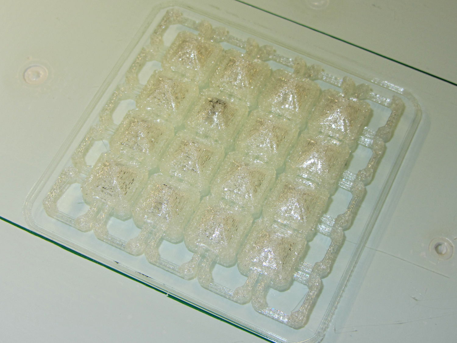
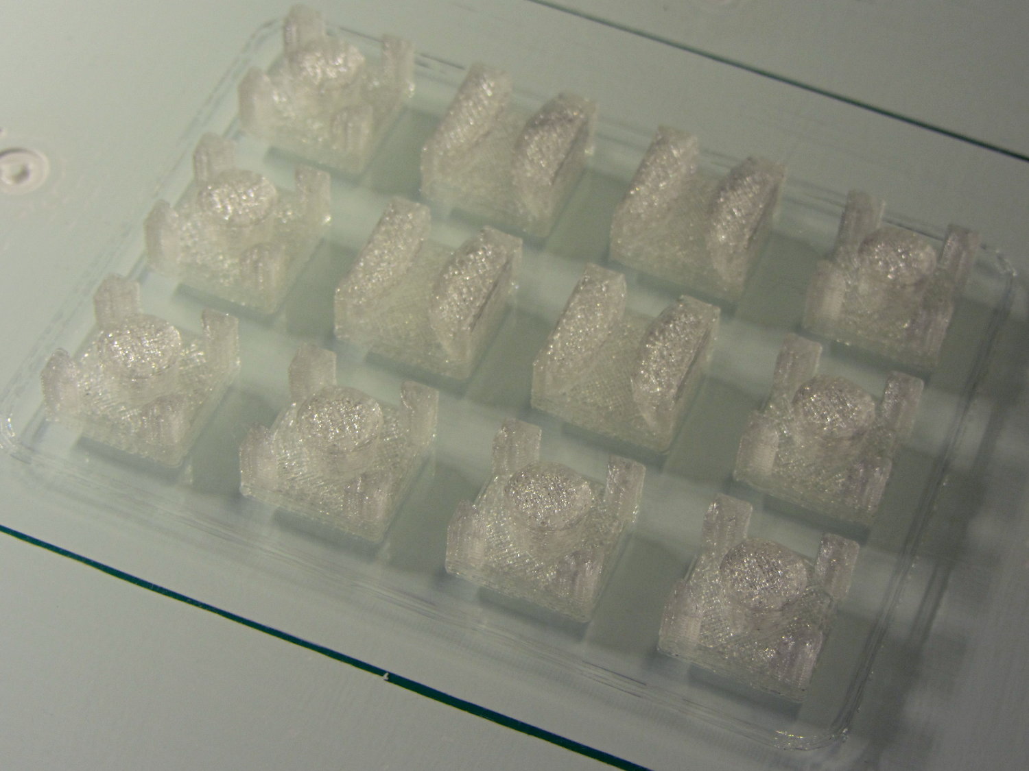
Reducing the link bars to 4×4 threads produced a diminutive patch:
Square Armor – small links – platform
Most of the dark smudges come from optical effects in the natural PLA filament, but the second-from-upper-left armor button contains a dollop of black PLA left in the nozzle from the end of that spool; running meters and meters of filament through the extruder isn’t enough to clean the interior. I now have some filament intended to clean the extruder, but it arrived after the black ran out.
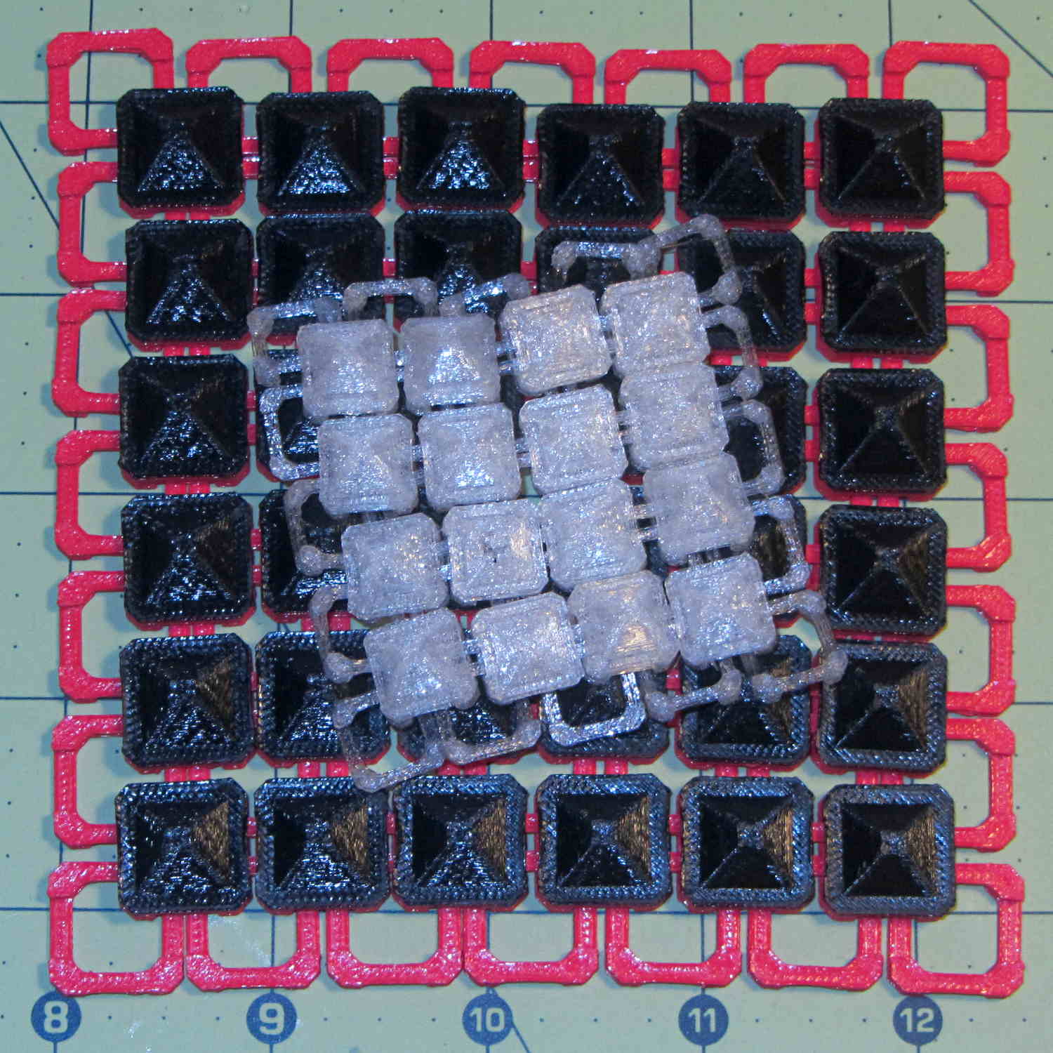
Comparing the patch with the original buttons shows the size difference:
Square Armor – large vs small links
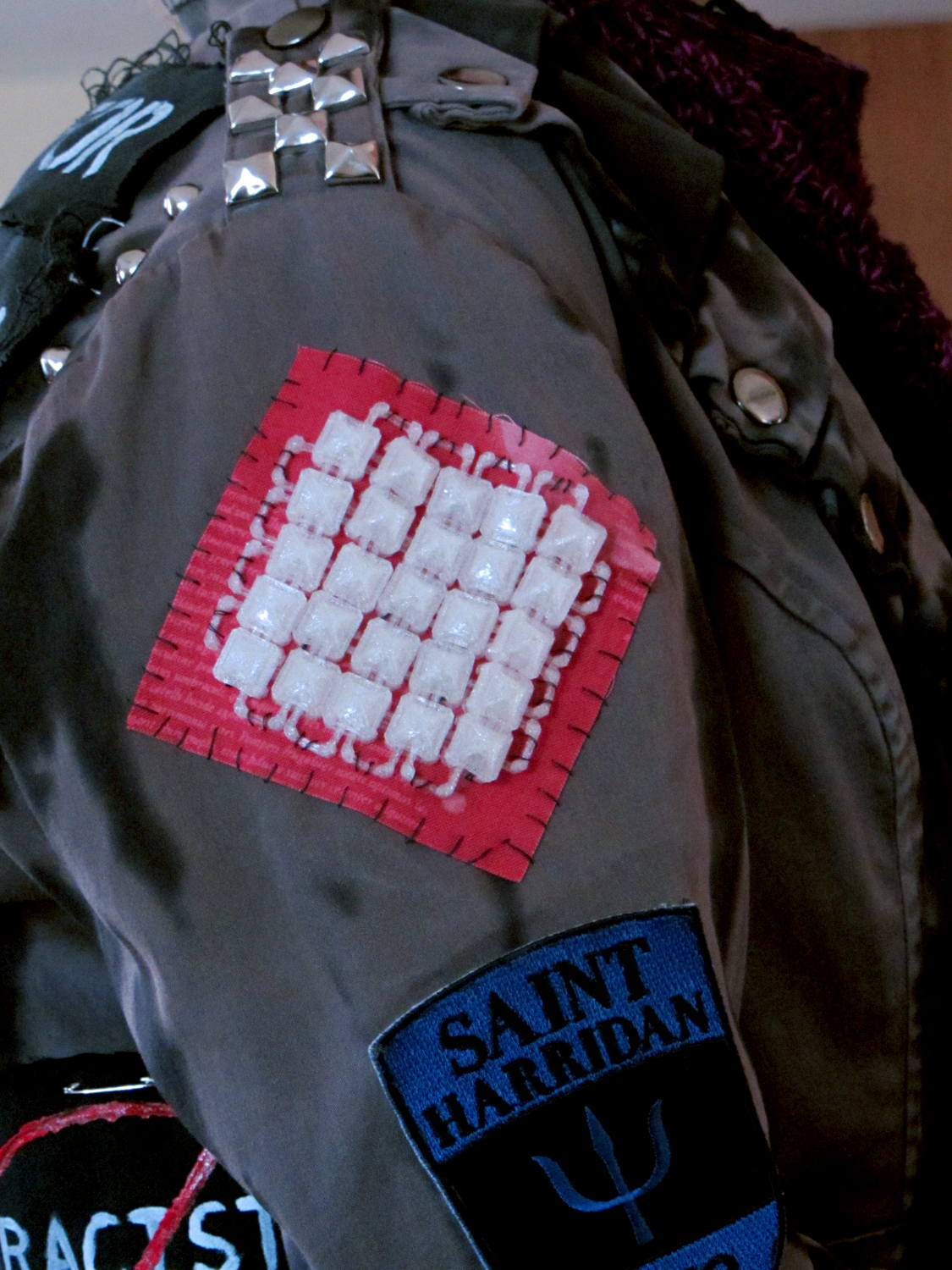
A trial fit suggested a 5×5 patch would fit better, so …
Square Armor – small links – mounted
The whip stitching accentuates the jacket’s style. We I think a glittery piping cord square around the armor links would spiff it up enormously and hide the open links, but that’s in the nature of fine tuning.
I’ll eventually see what happens with 3×3 thread = 1.2×0.6 mm links, which may be too small for reliable bridging and too delicate for anything other the finest evening wear.