You can buy new plotter pens for HP 7475A plotters at a bit over four bucks apiece and new-old-stock HP pens appear on eBay with similar prices, but what’s the fun in that?
You can refill the HP pens with liquid ink and continue plotting until the fiber tip wears out. That would limit me to the CMYK inkjet inks on the shelf, although I suppose investing in drafting inks might be amusing.
You can get refillable Koh-I-Noor pens and adapters, intended for specialized paper / vellum, at nearly $100 all-in per pen, plus ink & supplies, plus a hassle factor exceeding that of the continuous flow ink system on the Epson R380.
However, it should be feasible to build an adapter to hold an ordinary, albeit skinny, drawing / drafting pen, perhaps chopped down to be only a bit longer than the OEM plotter pens. That has the advantage of using cheap & readily available materials, doesn’t require much capital outlay, and, come to think of it, gives me a Digital Machinist column topic… [grin]
This is not, by any stretch of the imagination, a novel idea.
There’s a vague notion of converting the plotter into a vinyl / paper / stencil cutter, although I expect the snap-in pen holder can’t exert enough lateral force to hold a cutting knife in position, nor enough downward force to push the blade through the vinyl / paper / whatever. But ya never know until you try.
So, we begin…
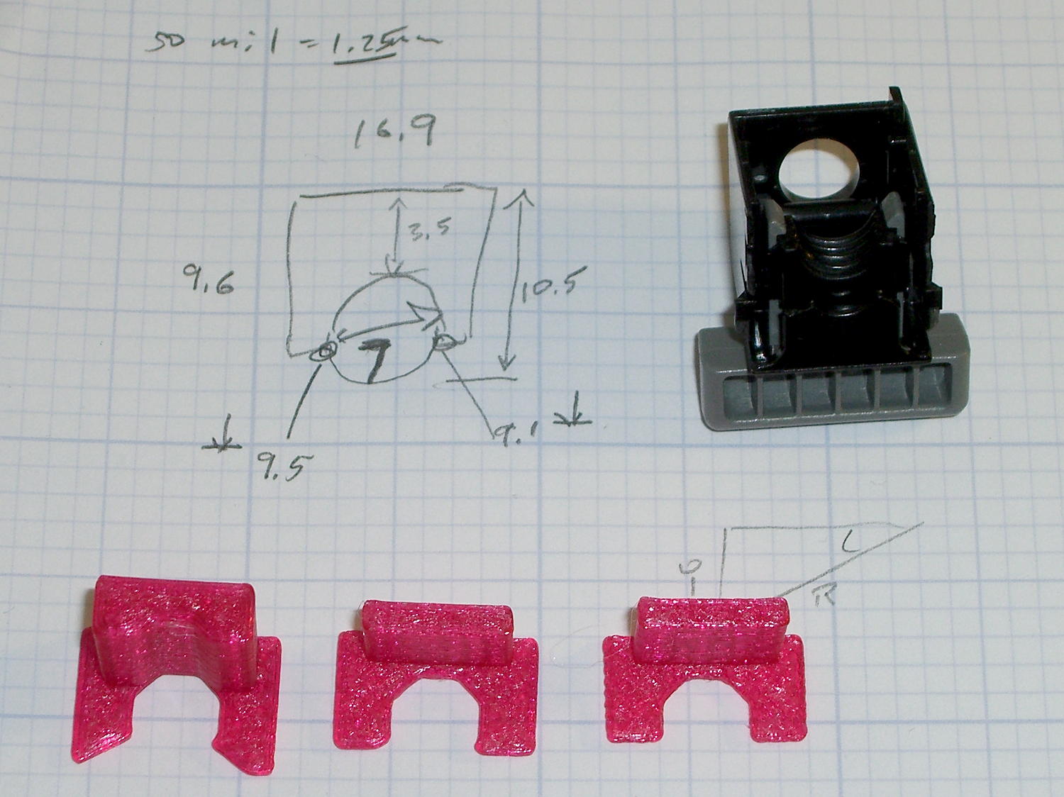
A bit of digital caliper work provides a list of points defining the OEM pen body outline:
RADIUS = 0; // subscript for radius values
HEIGHT = 1; // ... height above Z=0

BodyOutline = [						// X values = (measured diameter)/2, Y as distance from tip
	[0.0,0.0],						//  0 fiber pen tip
//	[2.0/2,1.4],					//  1 ... taper (not buildable)
	[1.0/2,0.005],					//  1 ... faked point to remove taper
	[2.0/2,0.0],[2.0/2,2.7],		//  2 ... cylinder
	[3.7/2,2.7],[3.7/2,4.45],		//  4 tip surround
	[4.8/2,5.2],					//  6 chamfer
	[6.5/2,11.4],					//  7 rubber seal face
	[8.9/2,11.4],					//  8 cap seat
	[11.2/2,15.9],					//  9 taper to body
	[11.5/2,28.0],					// 10 lower body
	[13.2/2,28.0],[16.6/2,28.5],	// 11 lower flange = 0.5
	[16.6/2,29.5],[13.2/2,30.0],	// 13 flange rim = 1.0
	[11.5/2,30.0],					// 15 upper flange = 0.5
	[11.5/2,43.25],					// 16 upper body
	[0.0,43.25]						// 17 lid over reservoir
	];
Rather than computing the radius by hand, it’s easier to just divide the easily measured diameter by two and be done with it.
The point array defines a polygon in the XY plane:
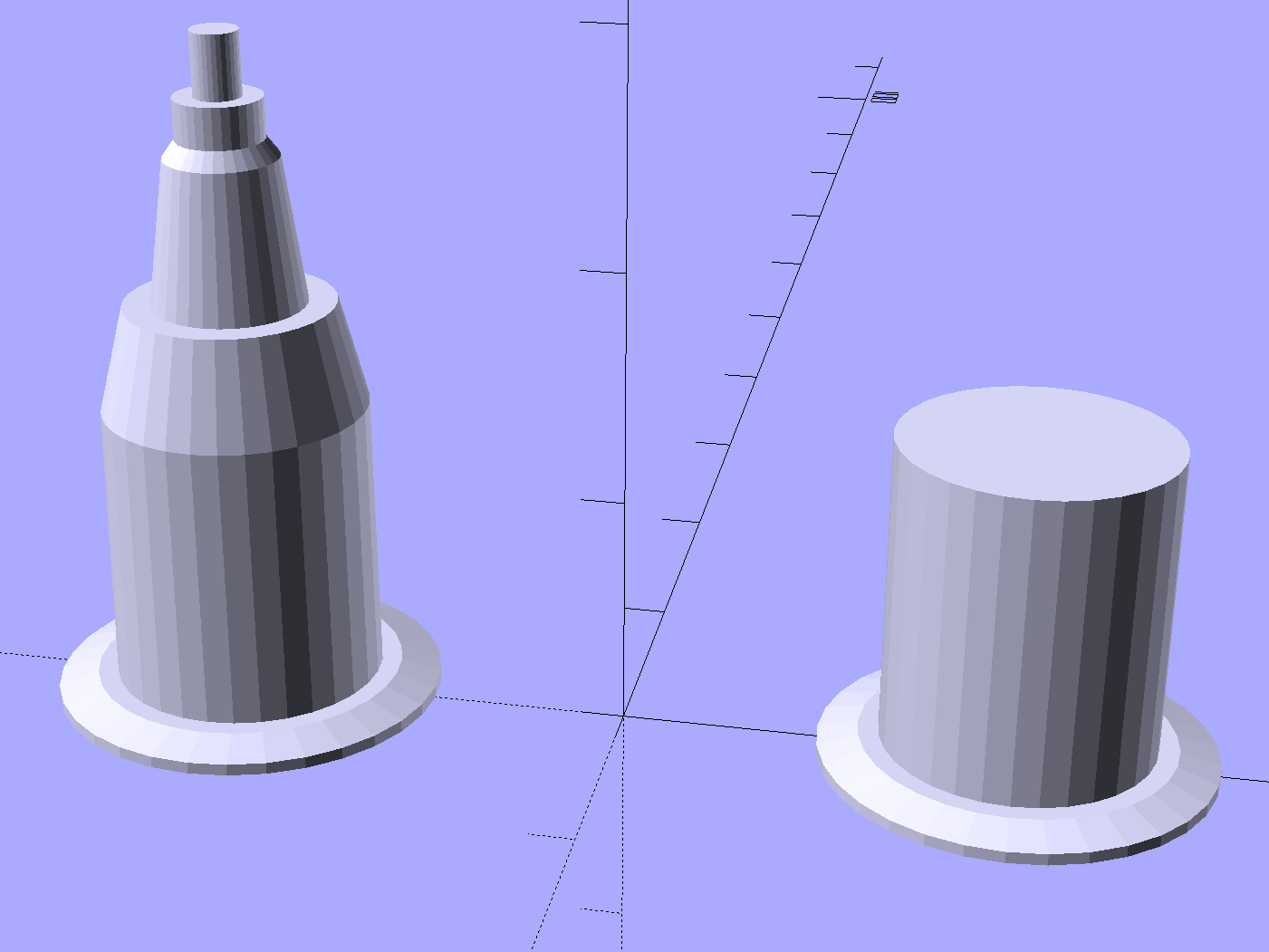
Then you feed that polygon into a rotate_extrude(), which spins up a reasonable simulacrum of a plotter pen:
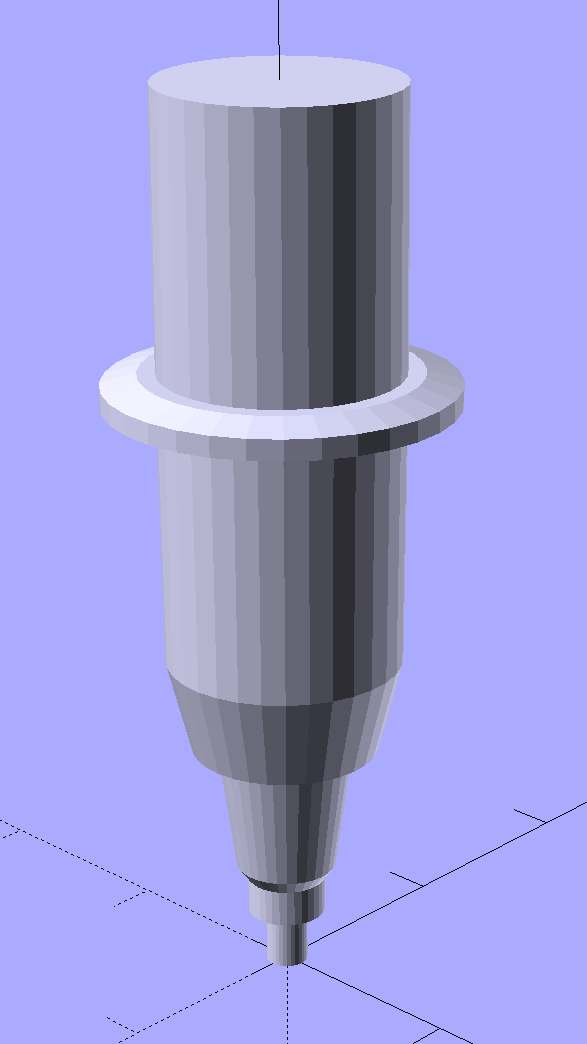
I picked the coordinates to put the tip at (0,0,0) and converted the tapered fiber nib into a plain cylinder.
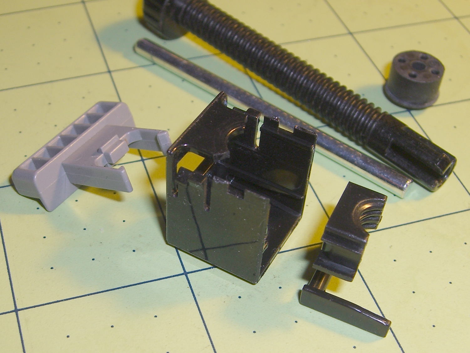
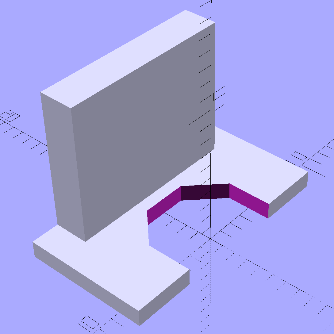
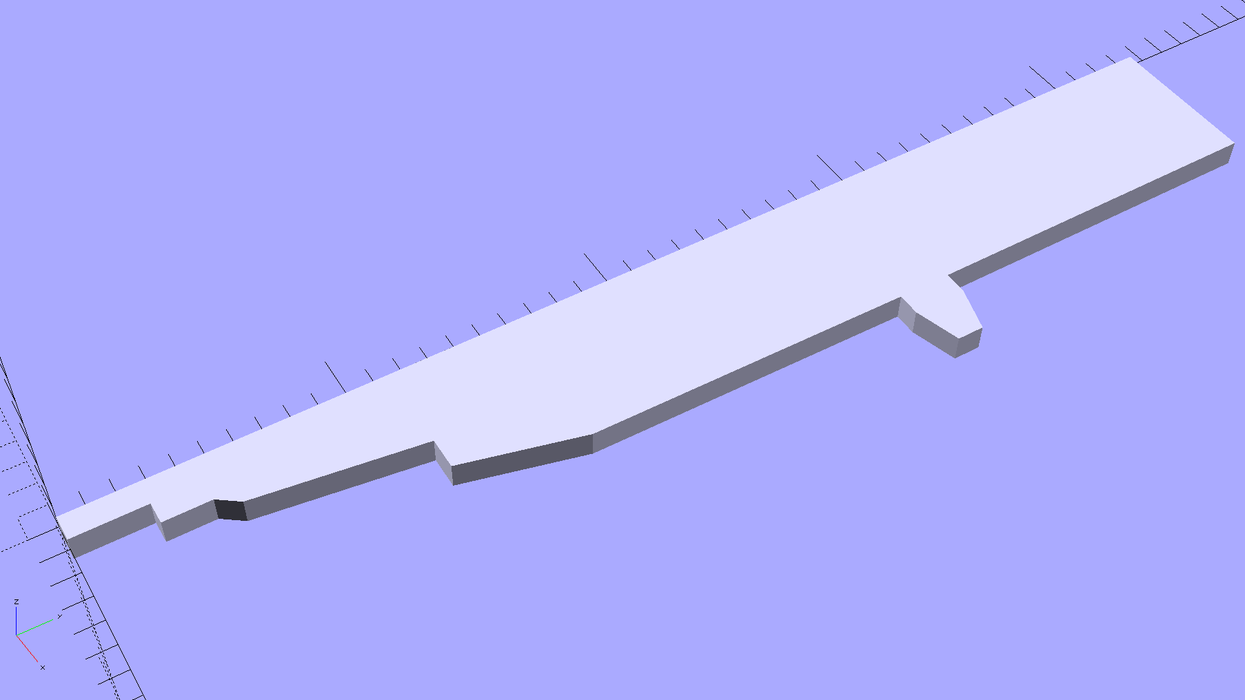
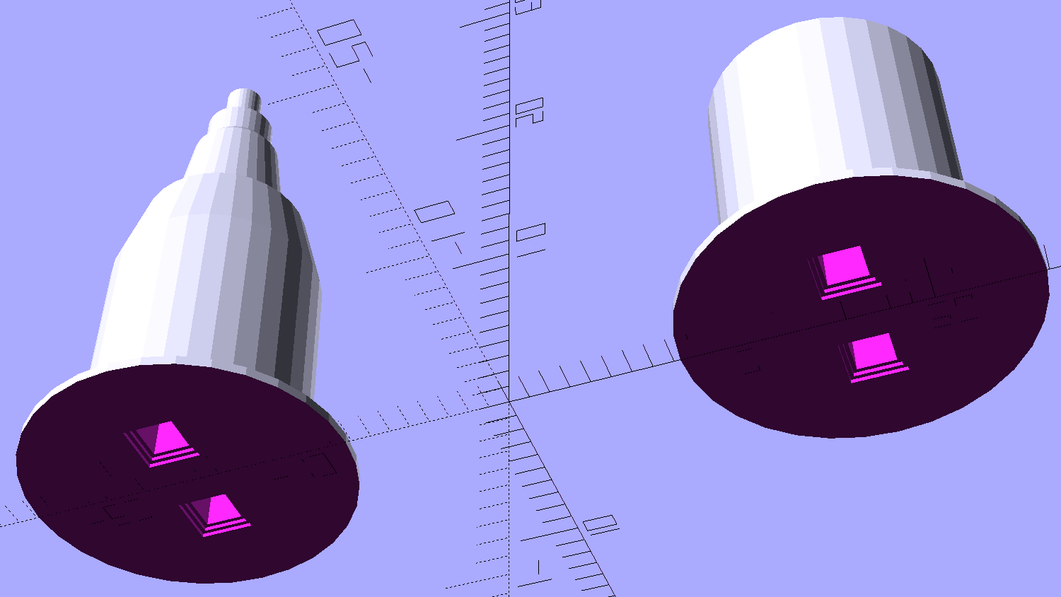
That shape is obviously impossible to print without vast amounts of support, but splitting it across the middle of the flange and rearranging the pieces works just fine:
A pair of alignment pin holes simplifies gluing the parts back together:
There’s a subtle problem lurking in that flange, which is 2.0 mm thick at the base and 1.0 mm thick at the rim. Splitting it in half requires each part to build correctly from an integral number of thread layers, so you must use a thread thickness (that’s in the Z direction) that divides evenly into the required height. I’ve been using 0.2 mm, which would produce a 1.2 mm rim.
Slicing at 0.25 mm produced a 2.1 mm flange with a 1.1 mm rim, suggesting that:
- The first layer is 0.05 mm too thick, slightly more than suggested by the skirts
- The glued joint isn’t 0.00 mm thick
- Some combination or permutation of those
I could apply a Slic3r Modifier Mesh to print the flange with 0.10 mm layers, but that seems like entirely too much effort right now.
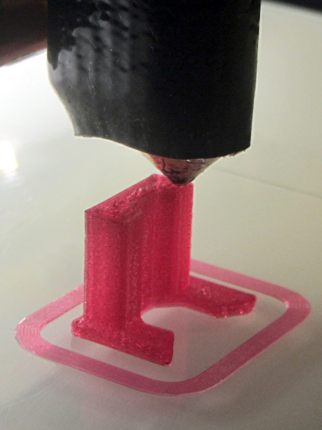
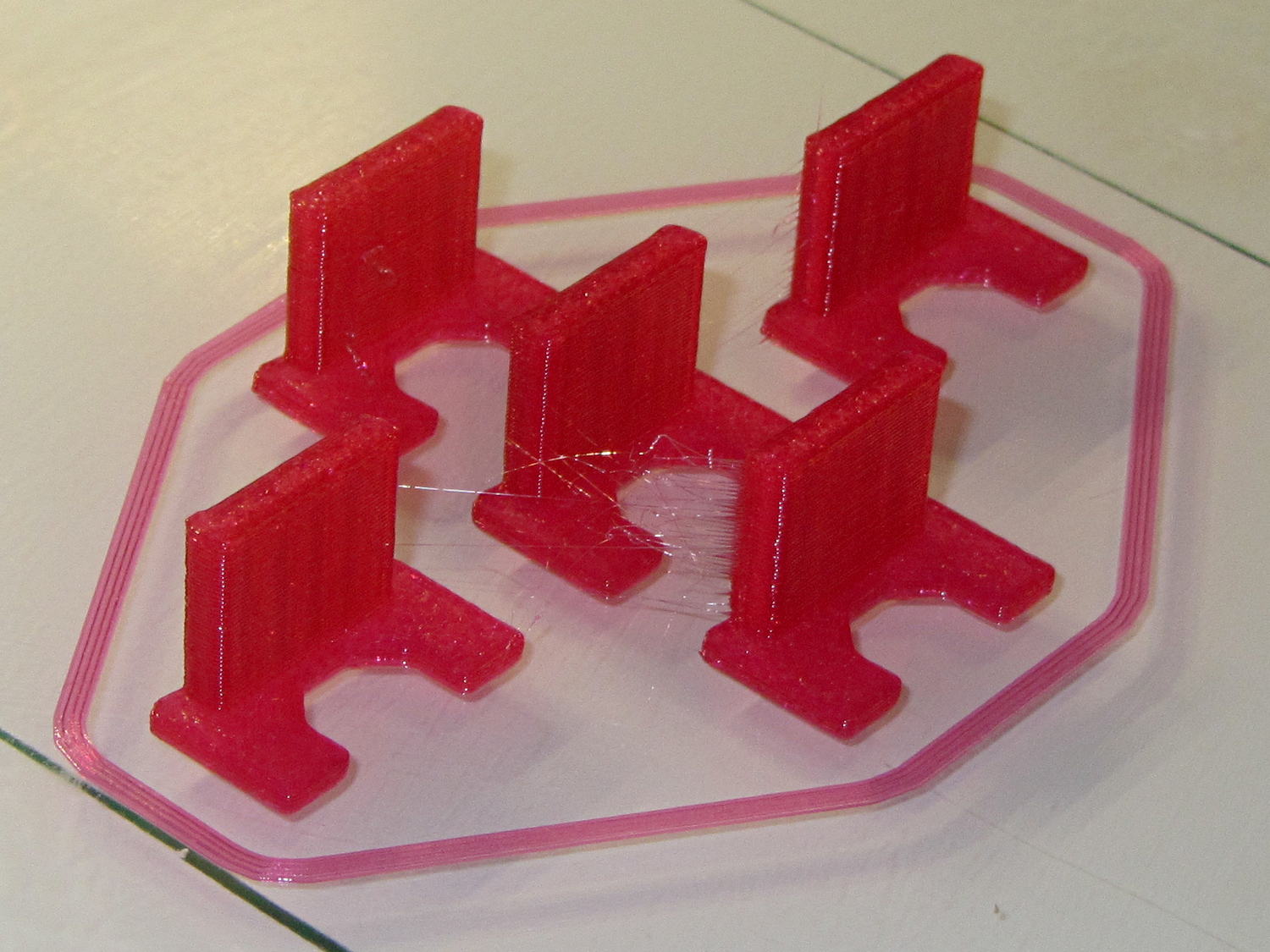
At the other end of the model, converting the tapered tip into a blunt cylinder didn’t save it from melting down:
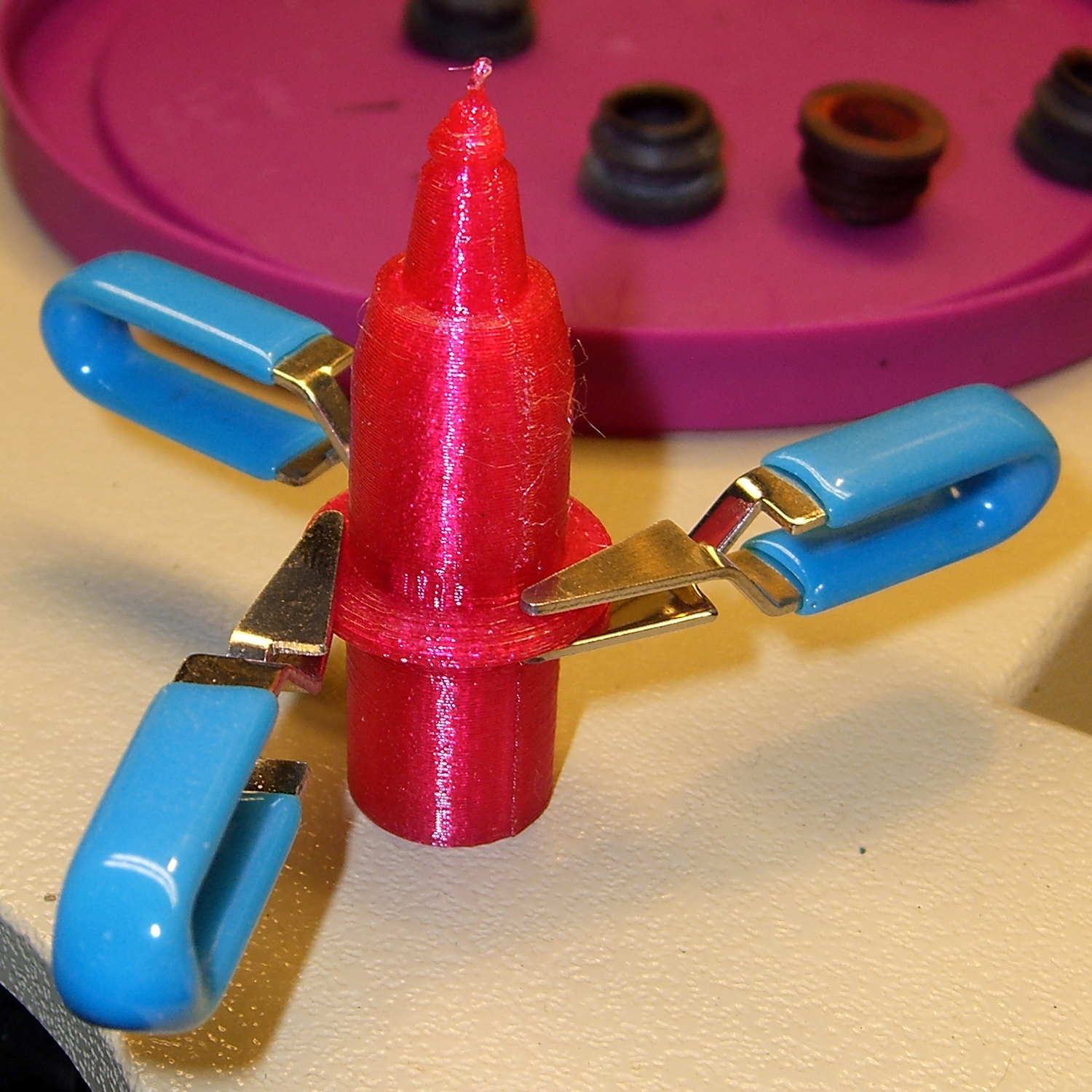
It might be possible to reduce the printing speed enough to produce that tiny cylinder, but I needed just the upper body to verify that it fit correctly into the carousel:

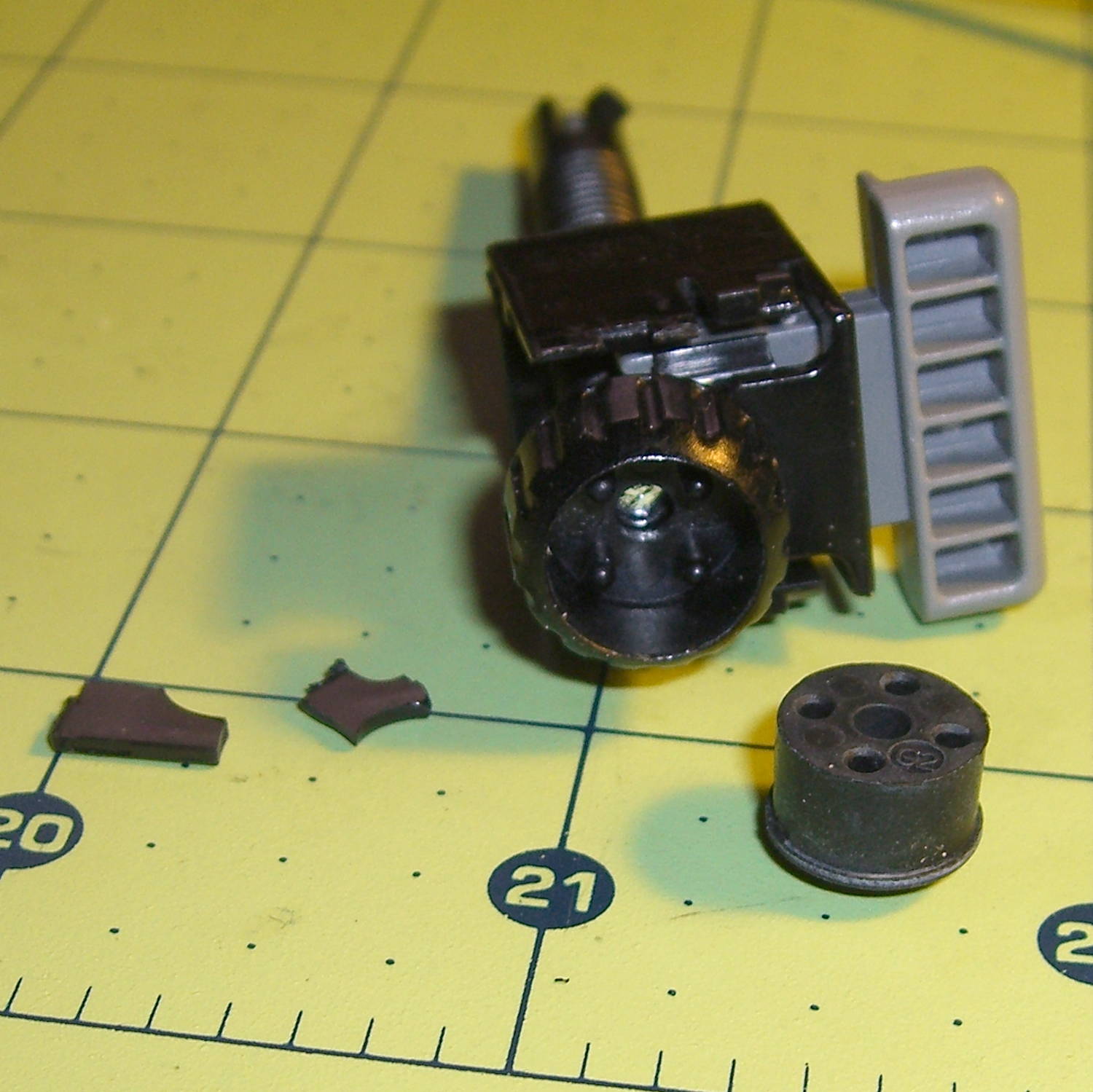
As you’d expect, the rubber boots that used to seal the pen tips have long since rotted out:
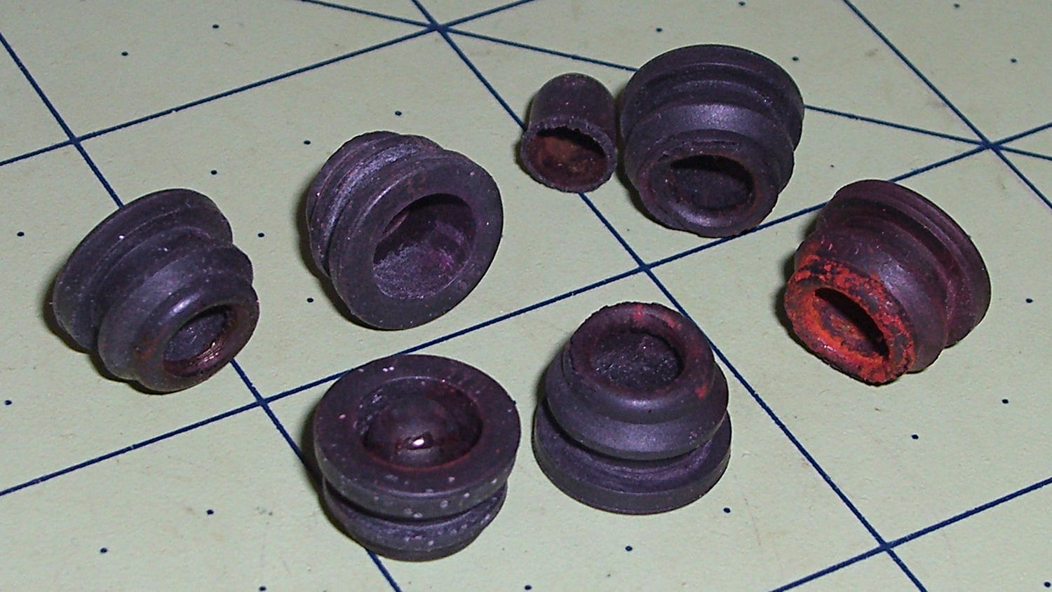
You can find sources for those boots, but at $252 (marked down to $144!) each, perhaps it’d be more feasible to gimmick up a two-part mold and cast silicone rubber duplicates; I could sell a set of six for $200 and get rich. Heck, I could even undercut their $40.32 two-year protection plan by a considerable margin.
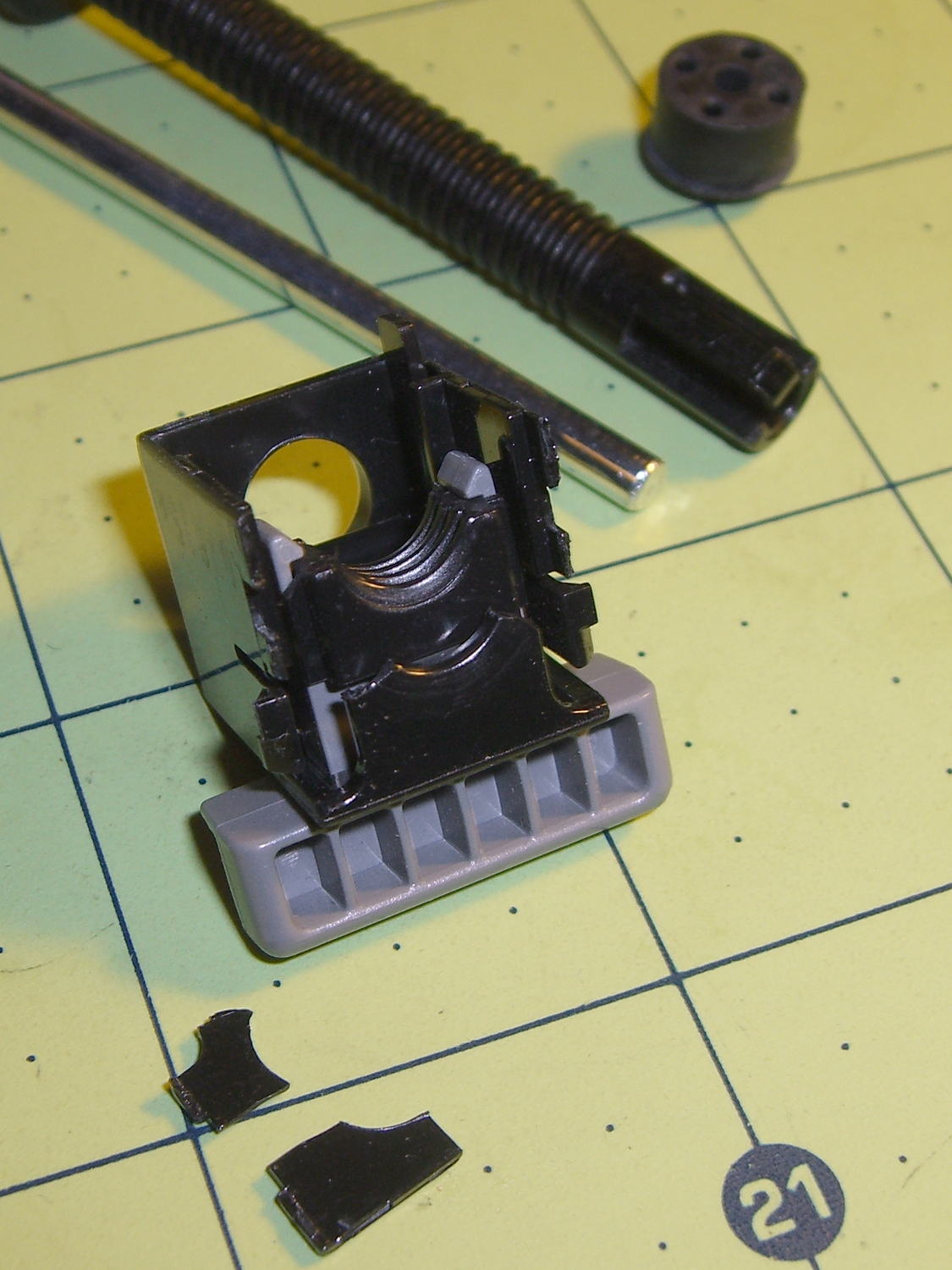
Anyhow, the pen holder plucked it out of the carousel just like a real HP pen:

Note that the carousel and pen holder contact the flange and the cylindrical body, not either of the tapered sections down to the tip. That means I can carve away the entire bottom part of the body to make a drawing pen adapter…
The OpenSCAD source code includes a bunch of features & parts I’ll describe in the next few posts, but which certainly should not be regarded as final copy:
// HP7475A plotter pen adapters
// Ed Nisley KE4ZNU April 2015

Layout = "BuildBody";		// ShowKnife BuildKnife KnifeAdapter
							// ShowPen BuildPen Plug
							// ShowBody BuildBody
							// Pen Knife
							// Stabilizer BuildStabilizer

//- Extrusion parameters must match reality!

ThreadThick = 0.25;
ThreadWidth = 0.40;

HoleWindage = 0.2;

Protrusion = 0.1;			// make holes end cleanly

inch = 25.4;

function IntegerMultiple(Size,Unit) = Unit * ceil(Size / Unit);

//----------------------
// Dimensions
// Z=0 at pen tip!

NumSides = 8*4;						// number of sides on each "cylinder"

RADIUS = 0;							// subscript for radius values
HEIGHT = 1;							//   ... height above Z=0

//-- Original HP plotter pen, which now serves as a body for the actual pen

BodyOutline = [						// X values = (measured diameter)/2, Y as distance from tip
	[0.0,0.0],						//  0 fiber pen tip
//	[2.0/2,1.4],					//  1 ... taper (not buildable)
	[1.0/2,0.005],					//  1 ... faked point to remove taper
	[2.0/2,0.0],[2.0/2,2.7],		//  2 ... cylinder
	[3.7/2,2.7],[3.7/2,4.45],		//  4 tip surround
	[4.8/2,5.2],					//  6 chamfer
	[6.5/2,11.4],					//  7 rubber seal face
	[8.9/2,11.4],					//  8 cap seat
	[11.2/2,15.9],					//  9 taper to body
	[11.5/2,28.0],					// 10 lower body
	[13.2/2,28.0],[16.6/2,28.5],	// 11 lower flange = 0.5
	[16.6/2,29.5],[13.2/2,30.0],	// 13 flange rim = 1.0
	[11.5/2,30.0],					// 15 upper flange = 0.5
	[11.5/2,43.25],					// 16 upper body
	[0.0,43.25]						// 17 lid over reservoir
	];

TrimHeight = BodyOutline[9][HEIGHT];		// cut off at top of lower taper
SplitHeight = (BodyOutline[11][HEIGHT] + BodyOutline[14][HEIGHT])/2;	// middle of flange

FlangeOD = 2*BodyOutline[13][RADIUS];
FlangeTop = BodyOutline[15][HEIGHT];

BodyOD = 2*BodyOutline[16][RADIUS];
BodyOAL = BodyOutline[17][HEIGHT];

echo(str("Trim: ",TrimHeight));
echo(str("Split: ",SplitHeight));

BuildSpace = FlangeOD;

//-- Sakura Micron fiber-point pen

ExpRP = 0.15;						// expand critical sections (by radius)

//-- pen locates in holder against end of outer body

PenOutline = [
	[0,0],							//  0 fiber pen tip
	[0.6/2,0.0],[0.6/2,0.9],		//  1  ... cylinder
	[1.5/2,0.9],[1.5/2,5.3],		//  3 tip surround
	[4.7/2,5.8],					//  5 chamfer
	[4.9/2,12.3],					//  6 nose
//	[8.0/2,12.3],[8.0/2,13.1],		//  7 latch ring
//	[8.05/2,13.1],[8.25/2,30.5],	//  9 actual inner body
	[8.4/2 + ExpRP,12.3],[8.4/2 + ExpRP,30.5],	//  7 inner body - clear latch ring
	[9.5/2 + ExpRP,30.5],			//  9 outer body - location surface!
	[9.8/2 + ExpRP,50.0],			// 10 outer body - length > Body
	[7.5/2,50.0],					// 11 arbitrary length
	[7.5/2,49.0],					// 12 end of reservoir
	[0,49.0]						// 13 fake reservoir
	];

PenNose = PenOutline[6];
PenLatch = PenOutline[7];

PenOAL = PenOutline[11][HEIGHT];

PlugOutline = [
	[0,0],							// 0 center of lid
	[9.5/2,0.0],[9.5/2,1.0],		// 1 lid rim
	[7.8/2,1.0],					// 3 against end of pen
	[7.3/2,6.0],					// 4 taper inside pen
	[5.3/2,6.0],					// 5 against ink reservoir
	[4.0/2,1.0],					// 6 taper to lid
	[0.0,1.0]						// 7 flat end of taper
	];

PlugOAL = PlugOutline[5][HEIGHT];

//   cap locates against end of inner body at latch ring
//-- cap origin is below surface to let pen tip be at Z=0

CapGap = 1.0;						// gap to adapter body when attached
CapGripHeight = 2.0;				// thickness of cap grip flange
CapTipClearance = 1.0;				// clearance under fiber tip

CapOffset = -(CapGripHeight + CapTipClearance);	// align inside at pen tip Z=0

CapOutline = [
	[0,CapOffset],									// 0 base
	[FlangeOD/2,CapOffset],							// 1 finger grip flange
	[FlangeOD/2,CapOffset + CapGripHeight],			// 2  ... top
	[BodyOD/2,CapOffset + CapGripHeight],			// 3 shaft
	[BodyOD/2,TrimHeight - CapGap],					// 4  ... top with clearance
	[PenLatch[RADIUS],TrimHeight - CapGap],			// 5 around pen latch ring
	[PenLatch[RADIUS],PenNose[HEIGHT]],				// 6  ... location surface!
	[PenNose[RADIUS] + ExpRP,PenNose[HEIGHT]],		// 7 snug around  nose
	[PenNose[RADIUS] + ExpRP,-CapTipClearance],		// 8 clearance around tip
	[0,-CapTipClearance],							// 9  ... bottom
	];

//-- Drag knife holder

ExpRK = 0.30;						// expand critical sections (by radius)
AdjLen = 2.0;						// allowance for adjustment travel

KnifeOutline = [
	[0,0],							//  0 blade point (actually 0.25 mm offset)
	[1.0/2,0.0],					//  1  ... blunt end
	[1.0/2,4.0],					//  2  ... cylinder
	[2.0/2,4.0],					//  3 shank
	[2.0/2,5.9],					//  4  .. at bearing
	[6.0/2,5.9],					//  5 holder - shell
	[7.3/2 + ExpRK,8.3],			//  6 holder - taper to body
	[7.3/2 + ExpRK,21.0 - AdjLen],	//  7 holder body
	[8.8/2 + ExpRK,22.0 - AdjLen],	//  8 holder - threads bottom
	[8.8/2 + ExpRK,25.0],[9.0/2 + ExpRK,26.0],		//  9 clear threads to reduce friction
	[9.0/2 + ExpRK,32.0],[8.8/2 + ExpRK,33.0],		// 11  ... end clearance
	[8.8/2 + ExpRK,42.5 - AdjLen],	// 13 holder - threads top = locknut bottom
	[12.5/2,42.5 - AdjLen],			// 14 knurled locknut - adjustment travel
	[12.5/2,45.8],					// 15 knurled locknut - top
	[11.0/2,45.8],					// 16 holder - adjusting knurl
	[11.0/2,52.0],					// 17 holder - top surface
	[3.0/2,52.0],[3.0/2,57.2],		// 18 spring post
	[0.0,57.2]						// 19 end of post
	];

ThreadLength = KnifeOutline[13][HEIGHT] - KnifeOutline[8][HEIGHT];

//-- Plotter pen holder stabilizer

HolderPlateThick = 3.0;				// thickness of plate atop holder
RimHeight = 5.0;					// rim around sides of holder
RimThick = 2.0;

HolderOrigin = [17.0,12.2,0.0];		// center of pen relative to polygon coordinates

HolderZOffset = 30.0;				// top of holder in pen-down position
HolderTopThick = 1.7;				// top of holder to top of pen flange
HolderCylinderLength = 17.0;		// length of pen support structure

HolderKnifeOffset = -2.0;			// additional downward adjustment range (not below top surface)

LockScrewInset = 3.0;				// from right edge of holder plate
LockScrewOD = 2.0;					// tap for 2.5 mm screw

// Beware: update hardcoded subscripts in Stabilizer() when adding / deleting point entries

HolderPlate = [
	[8.6,18.2],[8.6,23.9],			// 0 lower left corner of pen recess
	[13.9,23.9],[13.9,30.0],		// 2
//	[15.5,30.0],[15.5,25.0],		// 4 omit middle of support beam
//	[20.4,25.0],[20.4,30.0],		// 6
	[22.7,30.0],[22.7,27.5],		// 4
	[35.8,27.5],[35.8,20.7],		// 6 spring box corner
	[43.0,20.7],					// 8
	[31.5,0.0],						// 9
//	[24.5,0.0],[24.5,8.0],			// 10 omit pocket above pen clamp
//	[22.5,10.0],[22.5,16.5],		// 12
//	[20.5,18.2]						// 14
	[13.6,0.0],						// 10
	[8.6,5.0]						// 11
	];

BeamWidth = HolderPlate[4][0] - HolderPlate[2][0];

//----------------------
// Useful routines

module PolyCyl(Dia,Height,ForceSides=0) {			// based on nophead's polyholes

  Sides = (ForceSides != 0) ? ForceSides : (ceil(Dia) + 2);

  FixDia = Dia / cos(180/Sides);

  cylinder(r=(FixDia + HoleWindage)/2,
           h=Height,
	   $fn=Sides);
}

//- Locating pin hole with glue recess
//  Default length is two pin diameters on each side of the split

PinOD = 1.75;
PinOC = BodyOD / 2;

module LocatingPin(Dia=PinOD,Len=0.0) {

	PinLen = (Len != 0.0) ? Len : (4*Dia);

	translate([0,0,-ThreadThick])
		PolyCyl((Dia + 2*ThreadWidth),2*ThreadThick,4);

	translate([0,0,-2*ThreadThick])
		PolyCyl((Dia + 1*ThreadWidth),4*ThreadThick,4);

	translate([0,0,-(Len/2 + ThreadThick)])
		PolyCyl(Dia,(Len + 2*ThreadThick),4);

}

module LocatingPins(Length) {
	for (i=[-1,1])
	translate([0,i*PinOC/2,0])
		rotate(180/4)
		LocatingPin(Len=Length);
}

//----------------------
// Basic shapes

//-- HP plotter pen body

module Body() {
	render(convexity=3)
		rotate_extrude($fn=NumSides)
			polygon(points=BodyOutline);
}

//-- HP plotter pen holder
//   the trim block offsets use magic numbers from the HolderPlate outline

module Stabilizer() {

	difference() {
		union() {
			translate(-HolderOrigin)													// put center of pen at origin
				difference() {
						render(convexity=4)
						linear_extrude(height=(HolderPlateThick + RimHeight))			// overall flange around edges
							offset(r=RimThick)
									polygon(points=HolderPlate);

						render(convexity=4)
						translate([0,0,-Protrusion])									// recess for pen holder plate
							linear_extrude(height=(RimHeight + Protrusion))
								polygon(points=HolderPlate);

						translate([HolderPlate[7][0] - Protrusion,HolderPlate[7][1] - Protrusion,-Protrusion])	// trim spring box from top plate
							cube([30,20,(RimHeight + HolderPlateThick + 2*Protrusion)]);

						translate([27.0,HolderPlate[6][1] - Protrusion,-Protrusion])	// trim pivot plate clearance
							cube([30,20,(RimHeight + HolderPlateThick + 2*Protrusion)]);

						translate([HolderPlate[2][0],20,-Protrusion])					// trim left support beam
							cube([BeamWidth,20,(RimHeight + Protrusion)]);

						translate([HolderPlate[9][0] - LockScrewInset,RimThick,RimHeight - HolderTopThick - LockScrewOD/2])												// lock screw on front edge
							rotate([90,0,0])
								rotate(180/4)
									PolyCyl(LockScrewOD,3*RimThick);					// hold-down screw hole
				}

			translate([0,0,(RimHeight - HolderCylinderLength + Protrusion)])
				cylinder(d=BodyOD,h=HolderCylinderLength + Protrusion,$fn=NumSides);				// surround knife threads
		}

		translate([0,0,-HolderZOffset + HolderKnifeOffset])
			Knife();
	}
}

//-- Sakura drawing pen body

module Pen() {
	rotate_extrude($fn=NumSides)
		polygon(points=PenOutline);
}

//-- Plug for top of Sakura pen

module Plug() {
	render(convexity = 2)
		rotate_extrude($fn=NumSides)
			polygon(points=PlugOutline);
}

//-- Cap for tip of Sakura pen

module Cap() {
	render(convexity = 2)
		rotate_extrude($fn=NumSides)
			polygon(points=CapOutline);
}

//-- Sakura pen adapter

module PenAdapter(TrimZ = false) {

Trans = TrimZ ? - TrimHeight : 0;

	render(convexity=5)
		translate([0,0,Trans])
			difference() {
				Body();
				Pen();
				translate([0,0,TrimHeight/2])
					cube([2*FlangeOD,2*FlangeOD,TrimHeight],center=true);
			}
}

//-- Roland knife body

module Knife() {
	render(convexity=3)
		rotate_extrude($fn=NumSides)
			polygon(points=KnifeOutline);
}

//-- Roland knife adapter

module KnifeAdapter(TrimZ = false) {

Trans = TrimZ ? - TrimHeight : 0;

	render(convexity=5)
		translate([0,0,Trans])
			difference() {
				Body();
				Knife();
				translate([0,0,TrimHeight/2])
					cube([2*FlangeOD,2*FlangeOD,TrimHeight],center=true);
			}
}

//----------------------
// Build it

if (Layout == "Pen")
	Pen();

if (Layout == "Knife")
	Knife();

if (Layout == "Stabilizer")
	Stabilizer();

if (Layout == "ShowBody")
	Body();

if (Layout == "BuildBody")
	difference() {
		union() {
			translate([BuildSpace,0,-SplitHeight])
				Body();
			rotate([180,0,0])
				translate([-BuildSpace,0,-SplitHeight])
					Body();
		}
		translate([0,0,-BodyOAL])
			cube(2*BodyOAL,center=true);
		for (i = [-1,1])
			translate([i*BuildSpace,0,0])
				LocatingPins(5.0);
	}

if (Layout == "Plug")
	Plug();

if (Layout == "KnifeAdapter")
	KnifeAdapter();

if (Layout == "ShowPen") {

	color("AntiqueWhite") {
		Pen();
		translate([-1.5*BodyOD,0,0])
			Pen();
	}
	color("Magenta",0.35) {
		translate([0,0,PlugOAL + PenOAL + 3.0])
			rotate([180,0,0])
				Plug();
		PenAdapter();
		Cap();
	}
	color("Magenta") {
		translate([1.5*BodyOD,0,PlugOAL + PenOAL + 3.0])
			rotate([180,0,0])
				Plug();
		translate([1.5*BodyOD,0,0]) {
			PenAdapter();
			Cap();
		}
	}

}

if (Layout == "ShowKnife") {

	color("Goldenrod") {
		Knife();
		translate([-1.5*BodyOD,0,0])
			Knife();
	}
	color("Magenta",0.35)
		KnifeAdapter();
	color("Magenta") {
		translate([1.5*BodyOD,0,0])
			KnifeAdapter();
	}

}

if (Layout == "BuildPen") {

	translate([0,BuildSpace/2,0])
		Plug();
	translate([0,-BuildSpace/2,-CapOffset])
		Cap();

	difference() {
		union() {
			translate([BuildSpace,0,-SplitHeight])
				PenAdapter(false);
			rotate([180,0,0])
				translate([-BuildSpace,0,-SplitHeight])
					PenAdapter(false);
		}
		translate([0,0,-BodyOAL])
			cube(2*BodyOAL,center=true);
	}

}

if (Layout == "BuildKnife") {

	difference() {
		union() {
			translate([BuildSpace,0,-SplitHeight])
				KnifeAdapter(false);
			rotate([180,0,0])
				translate([-BuildSpace,0,-SplitHeight])
					KnifeAdapter(false);
		}
		translate([0,0,-BodyOAL])
			cube(2*BodyOAL,center=true);
	}

}

if (Layout == "BuildStabilizer") {

	translate([0,0,(HolderPlateThick + RimHeight)])
		rotate([0,180,0])
			Stabilizer();
}