Ed Nisley's Blog: Shop notes, electronics, firmware, machinery, 3D printing, laser cuttery, and curiosities. Contents: 100% human thinking, 0% AI slop.
In late May we deployed six sticky traps in and around the onion bed, attempting to reduce the number of Onion Fly maggots. By mid-June the sheets were covered with the shredded leaves Mary uses to mulch the onions, but half a dozen flies were out of action:
Sticky trap – 2021-06
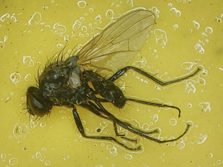
We’re pretty sure that’s what these things are:
Sticky trap – Onion Fly – 2021-06
They’re supposed to have red eyes, but being affixed to a sheet of snot for a few weeks doesn’t do the least bit of good for your eyes.
We replaced the sheets and left them in place until the end of July:
Sticky trap – 2021-07
The sheets took another half-dozen flies out of circulation, Mary began harvesting the onions, and observed it was the healthiest onion harvest she’s ever had.
We declared victory, removed the traps, and the remaining onions suffered considerable maggot damage over the next few weeks.
Anecdotally, it seems reducing the Onion Fly population by (what seems to be) a small amount and maintaining pressure on the population dramatically reduces the number of maggots available to damage the onion crop. At least for a single bed in a non-commercial setting.
The plural of anecdote is not anecdata, but we’ll try it again next year, leave the traps in place while the onions are in the ground, and see what happens.
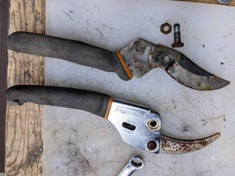
Mary found a rusted Fiskars bypass pruner in the trash pile near her Vassar Farms plot and brought it home for proper disposal. The nuts and screws responded to an overnight penetrating oil treatment and it came apart easily:
Fiskars bypass pruner – as found
The movable jaw may have once sported a PTFE coating, but it’s likely just a different steel alloy.
After scrubbing the pieces with an abrasive pad, a little diamond filing, and (at the insistence of the Squidwrench chorus) some Dremel wire-wheel action, it looks almost new:
Fiskars bypass pruner – restored
The blades sport a few nicks from their previous life, but work well enough.
This is laid in against a need I hope never occurs:
Dripworks 0.75 inch pipe clamp
It’s intended to clamp around one of the Dripworks mainline pipes carrying water from the pressure regulator to the driplines in the raised beds, should an errant shovel or fork find the pipe.
It descends from a long line of soaker hoseclamps, with a 25 mm ID allowing for a silicone tape wrap as a water barrier.
This file contains hidden or bidirectional Unicode text that may be interpreted or compiled differently than what appears below. To review, open the file in an editor that reveals hidden Unicode characters.
Learn more about bidirectional Unicode characters
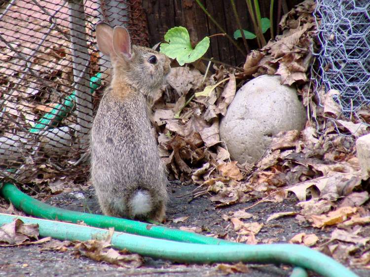
Mary chased a small rabbit out of her garden a few days ago, whereupon we up-armored a few vulnerable parts of the fence. The culprit turns out to be insufferably cute:
Young Rabbit – at the gate
You cannot be annoyed with something like this:
Young Rabbit – alert
Oh, yes, you can. Rabbits are basically eating machines:
Young Rabbit – grazing
They’re welcome to all the greenery in the yard, just nothing in the garden:
Young Rabbit – overcompressed A
It’s known as a 2×2 Bunny, because it can fit through that size opening in a chain link fence while traveling at a dead run.
This one has yet to learn about being wary around the Big People:
Young Rabbit – overcompressed B
The alert reader will have noted the crappy quality of the last three pictures, at least in comparison with the first two. It’s the difference between digital zoom on my Pixel 3a phone applied to a zoomed-all-the-way image and optical zoom on a “real” camera (admittedly, an old Sony DSC-H5). On the other paw, I had the phone in my pocket when Mary spotted the bunny on the driveway, which counts for everything in similar situations.
JPG compression doesn’t handle hair particularly well, so the low-res bunny wears a rather artistic brush-stroke coat; it’s OK if you like that sort of thing.
We recently installed a Dripworks drip irrigation system for Mary’s garden and, of course, pre-assembled the emitter / dripline tubing, fittings, and supply / filter / plumbing for each of the beds in the Basement Shop. A few days after burying the main lines, plumbing the filter + pressure regulator, and plugging in half a dozen bed assemblies, Mary noticed some emitter tubes weren’t delivering any water and other beds seemed too dry.
N.B.: We bought everything directly from Dripworks. This is not counterfeit crap from a sketchy Amazon seller.
I cut the dripline just downstream of the Micro-Flowvalve on a completely dry bed, whereupon no water emerged. Cutting the supply tube just upstream of the valve produced a jet squirting halfway along the bed. I tried and failed to blow air through the valve: it was completely blocked despite being in the “open” position. I installed another valve and the emitter tube started working properly.
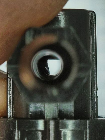
I sat down at the kitchen table with a bag of unused valves and peered through them (the pix are through the microscope):
Dripworks valve – mostly open lumen
That’s one of the better-looking valves, with only a little mold flash in the lumen.
Partially occluded lumens were more typical:
Dripworks valve – partially occluded lumen
Quite a few were almost completely obstructed:
Dripworks valve – mostly occluded lumen
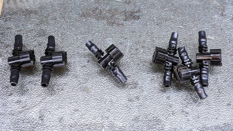
For lack of better instrumentation, I blew through the valves and sorted them by effort:
Dripworks valve – sorted by blockage
Two of the valves in the group on the left are completely blocked, with the others mostly blocked.
The middle group has enough mold flash to produce noticeable resistance to the air flow. I think water would have more trouble getting through, but the emitters would at least look like they’re delivering water.
The group on the right has mostly unblocked valves, with visible mold flash but little restriction.
I have no way to measure the actual water flow, so it’s entirely possible the QC spec allows considerable blockage while still delivering enough water to the emitters. More likely, the spec assumes a clear lumen and the mold flash is a total QC faceplant; it’s obviously not a controlled quantity.
Well, I can fix that:
Dripworks valve – drilling
That’s a 2.3 mm drill going straight through the valve body. I drilled the valves from both ends and blew out the swarf:
Dripworks valve – drill swarf
That produced twenty valves with clear lumens. Of course, the drill leaves a slightly rough interior surface, but it’s now much easier to blow air through them.
We hadn’t installed the driplines in two beds with three emitter tubes per bed. I cut out those six unused valves and sorted them by resistance:
Dripworks valve – six samples
Both of the valves on the left are blocked, the three on the right are mostly OK, and the one in the middle is partially blocked.
With two dozen repaired valves in hand, we returned to the garden, I cut 22 valves out of the installed driplines and replaced them under field conditions. Returning to the Basement Laboratory, I blew the water out (*), sorted them by resistance, and produced a similar distribution, albeit with no pictorial evidence. Although we have no immediate need for the used valves, they’re drilled out and ready for use.
In very round numbers, you should expect:
A third of Dripworks valves will pass (close to) the expected flow
A third will have a minor flow restriction
A quarter will have a severe flow restriction
One valve in ten will be completely blocked
Plan to drill out all the Micro-Flow valves before you assemble your driplines.
AFAICT, none of the other ¼ inch fittings we used have any interior flash, so it’s only a problem with the valves.
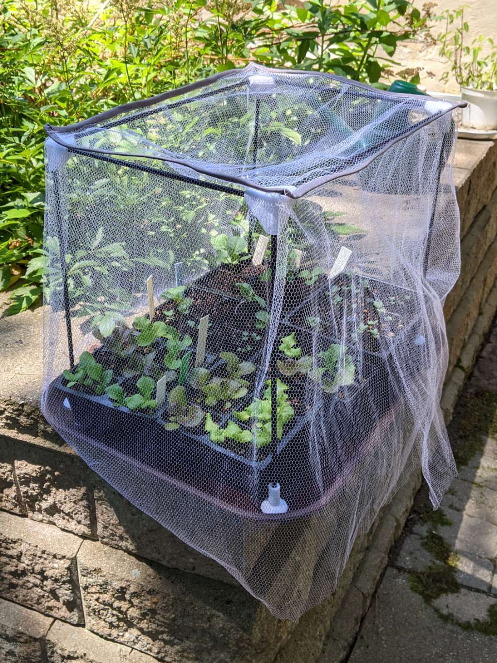
The objective being to reduce the number of onion maggots in Mary’s Vassar Farm plot without chemical agents, I conjured sticky trap screen frames from the vasty digital deep:
Sticky Trap – first production run
Each one contains half a sheet of yellow sticky plastic, which is easy enough to cut before peeling off the protective covering sheets. The cage is half-inch galvanized hardware cloth snipped with hardened diagonal cutters. A bead of acrylic adhesive around the base holds the cage in place
Although you can deploy sticky sheets without cages, they tend to attract and affix beneficial critters: butterflies, small birds, furry critters, toads, gardeners, and the like. We don’t know how effective the cages will be, but they seemed better than nothing.
They mount on ski poles cut in half:
Sticky Trap – ski pole installed
And on fence posts around the perimeter:
Sticky Trap – angle bracket installed
To my untrained eye, some of those doomed critters are, indeed, onion maggot flies. The rest seem to be gnats and other nuisances, so IMO we’re applying population pressure in the right direction.
Each base-and-cap frame takes about three hours to print, so I did them one at a time over the course of a few days while applying continuous product improvement.
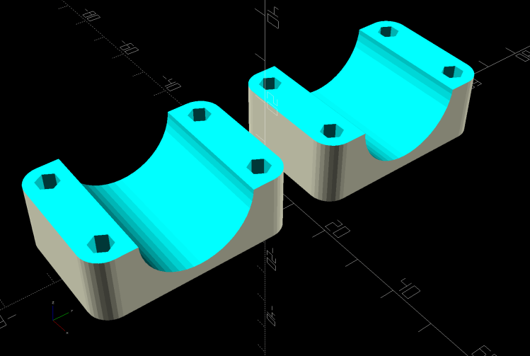
The sheets rest on small V blocks intended to keep them centered within the cage:
Sticky Sheet Cage – angle bracket – solid model
The ski pole attachment must build with the cap on top, but it bridges well enough for the purpose:
Sticky Sheet Cage – ski pole – solid model
The overhanging hooks on the blocks (just barely) engage the grid to keep the lid in place, while remaining short enough to not droop too badly. You could probably delete the hooks from the bottom plate, but they align the cage while the adhesive cures.
The sheets tend to bend in the middle, so I’ll stick a thin slat or two vertically to keep them straight.
This file contains hidden or bidirectional Unicode text that may be interpreted or compiled differently than what appears below. To review, open the file in an editor that reveals hidden Unicode characters.
Learn more about bidirectional Unicode characters