The Smell of Molten Projects in the Morning

Ed Nisley's Blog: Shop notes, electronics, firmware, machinery, 3D printing, laser cuttery, and curiosities. Contents: 100% human thinking, 0% AI slop.

Tag: Gardening

Growing and sometimes fixing

  • Sticky Trap Screen Frames

    Sticky Trap Screen Frames

    The objective being to reduce the number of onion maggots in Mary’s Vassar Farm plot without chemical agents, I conjured sticky trap screen frames from the vasty digital deep:

    Sticky Trap - first production run
    Sticky Trap – first production run

    Each one contains half a sheet of yellow sticky plastic, which is easy enough to cut before peeling off the protective covering sheets. The cage is half-inch galvanized hardware cloth snipped with hardened diagonal cutters. A bead of acrylic adhesive around the base holds the cage in place

    Although you can deploy sticky sheets without cages, they tend to attract and affix beneficial critters: butterflies, small birds, furry critters, toads, gardeners, and the like. We don’t know how effective the cages will be, but they seemed better than nothing.

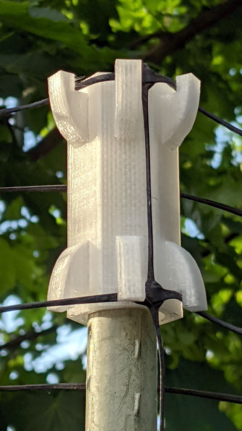
    They mount on ski poles cut in half:

    Sticky Trap - ski pole installed
    Sticky Trap – ski pole installed

    And on fence posts around the perimeter:

    Sticky Trap - angle bracket installed
    Sticky Trap – angle bracket installed

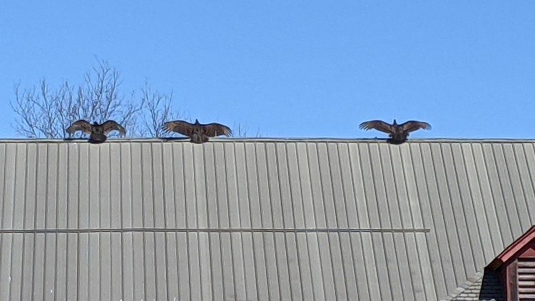
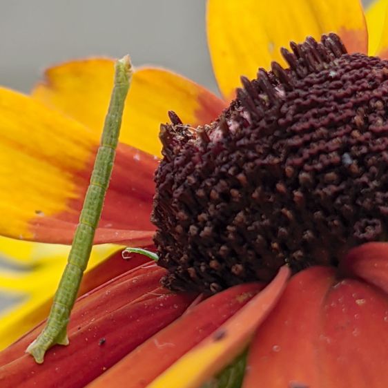
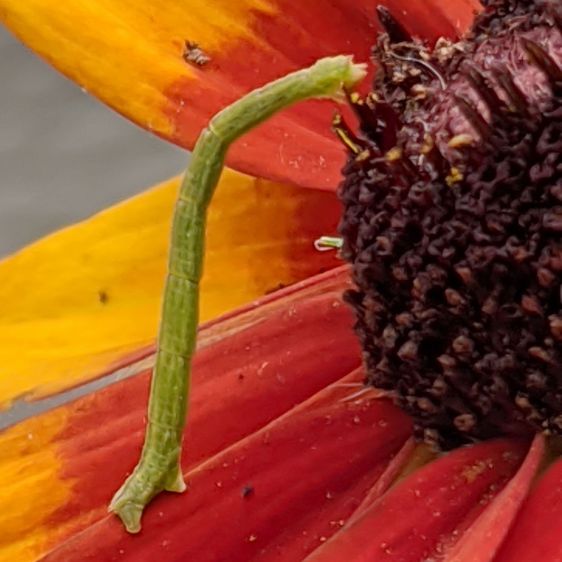
    To my untrained eye, some of those doomed critters are, indeed, onion maggot flies. The rest seem to be gnats and other nuisances, so IMO we’re applying population pressure in the right direction.

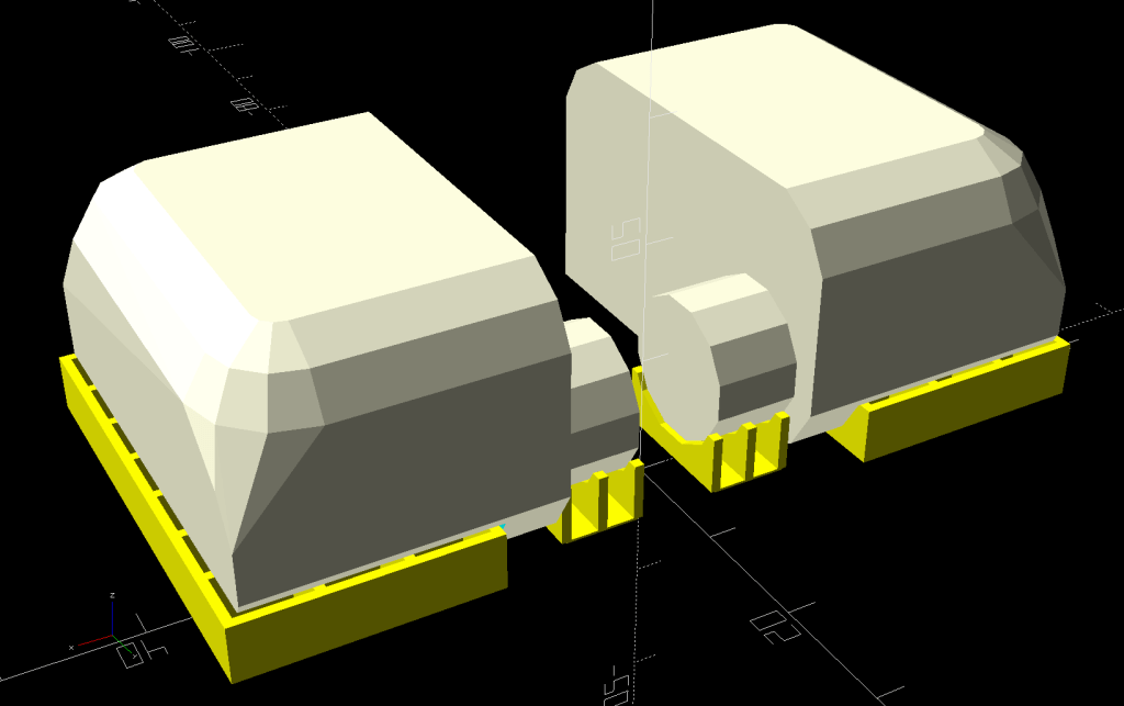
    Each base-and-cap frame takes about three hours to print, so I did them one at a time over the course of a few days while applying continuous product improvement.

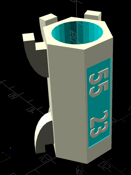
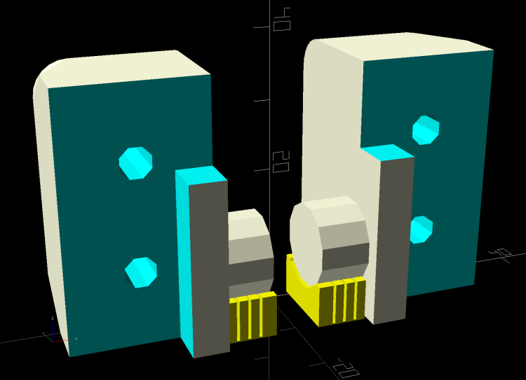
    The sheets rest on small V blocks intended to keep them centered within the cage:

    Sticky Sheet Cage - angle bracket - solid model
    Sticky Sheet Cage – angle bracket – solid model

    The ski pole attachment must build with the cap on top, but it bridges well enough for the purpose:

    Sticky Sheet Cage - ski pole - solid model
    Sticky Sheet Cage – ski pole – solid model

    The overhanging hooks on the blocks (just barely) engage the grid to keep the lid in place, while remaining short enough to not droop too badly. You could probably delete the hooks from the bottom plate, but they align the cage while the adhesive cures.

    The sheets tend to bend in the middle, so I’ll stick a thin slat or two vertically to keep them straight.

    The OpenSCAD source code as a GitHub Gist:

    // Sticky Sheet Cage
    // Ed Nisley KE4ZNU May 2021
    Layout = "Build"; // [Build, Show, Cap, Attachment]
    Bracket = "Ski"; // [Angle, Ski, Post]
    //- Extrusion parameters must match reality!
    /* [Hidden] */
    ThreadThick = 0.25;
    ThreadWidth = 0.40;
    HoleWindage = 0.2;
    Protrusion = 0.1; // make holes end cleanly
    inch = 25.4;
    ID = 0;
    OD = 1;
    LENGTH = 2;
    function IntegerMultiple(Size,Unit) = Unit * ceil(Size / Unit);
    //———————-
    // Dimensions
    Sheet = [1,100,150]; // sticky sheet
    Grid = 0.5*inch;
    Cage = [2*Grid + 5.0, 8*Grid + 5.0, 12*Grid + 2.0]; // grid wire cage bent around sheet
    CageRad = 2.5; // wire bending radius
    CageThick = 2.0; // grid thickness
    WallThick = 3.0; // min wall and bottom thickness
    Recess = 5.0; // inset to capture cage edge
    Plate = [Cage.x,Cage.y,Recess] + [2*WallThick,2*WallThick,WallThick];
    PlateRad = 5.0;
    SkiPole = [20.0,20.0 + 2*WallThick,50];
    AnglePlate = [30,30,50];
    ScrewClear = 5.0;
    BuildGap = 5.0;
    //———————-
    // Useful routines
    module PolyCyl(Dia,Height,ForceSides=0) { // based on nophead's polyholes
    Sides = (ForceSides != 0) ? ForceSides : (ceil(Dia) + 2);
    FixDia = Dia / cos(180/Sides);
    cylinder(r=(FixDia + HoleWindage)/2,
    h=Height,
    $fn=Sides);
    }
    //———————-
    // Pieces
    module Cap() {
    union() {
    difference() {
    hull()
    for (i=[-1,1], j=[-1,1])
    translate([i*(Plate.x/2 – PlateRad),j*(Plate.y/2 – PlateRad),0])
    cylinder(r=PlateRad,h=Plate.z,$fn=12);
    translate([0,0,Plate.z – Recess])
    hull()
    for (i=[-1,1], j=[-1,1])
    translate([i*(Cage.x/2 – CageRad),j*(Cage.y/2 – CageRad),0])
    cylinder(r=CageRad,h=Plate.z,$fn=12);
    }
    difference() {
    Strut = Cage.x – 2*CageThick;
    Latch = [Cage.x,WallThick,0.75*Plate.z];
    union() {
    for (j=[-1,1])
    translate([0,j*2.5*Grid,Plate.z])
    cube([Strut,WallThick,2*Plate.z],center=true);
    for (j=[-1,1])
    translate([0,j*2.5*Grid,2*Plate.z – Latch.z/2])
    cube(Latch,center=true);
    }
    translate([0,0,2*Plate.z + (Cage.z – Sheet.z)/4])
    rotate([0,45,0])
    cube([Strut/sqrt(2),Plate.y,Strut/sqrt(2)],center=true);
    }
    }
    }
    module Attachment() {
    if (Bracket == "Angle") {
    translate([0,Plate.y/2,0])
    rotate(45)
    difference() {
    union() {
    cube(AnglePlate,center=false);
    rotate(-45)
    translate([0,WallThick,Plate.z/2])
    cube([Plate.x – 2*PlateRad,4*WallThick,Plate.z],center=true);
    }
    translate([WallThick,WallThick,-Protrusion])
    cube(AnglePlate + [0,0,2*Protrusion],center=false);
    translate([AnglePlate.x/2,-Protrusion,2*AnglePlate.z/3])
    rotate([-90,0,0])
    PolyCyl(ScrewClear,2*AnglePlate.x,6);
    translate([-Protrusion,AnglePlate.x/2,1*AnglePlate.z/3])
    rotate([90,0,90])
    PolyCyl(ScrewClear,2*AnglePlate.x,6);
    }
    }
    else if (Bracket == "Ski") {
    translate([0,Plate.y/2 + SkiPole[OD]/2,0])
    difference() {
    union() {
    PolyCyl(SkiPole[OD],SkiPole[LENGTH],24);
    translate([0,-3*WallThick,Plate.z/2])
    cube([Plate.x – 2*PlateRad,4*WallThick,Plate.z],center=true);
    }
    translate([0,0,-2*WallThick])
    PolyCyl(SkiPole[ID],SkiPole[LENGTH],24);
    }
    }
    }
    //———————-
    // Build it
    if (Layout == "Cap")
    Cap();
    if (Layout == "Attachment") {
    Attachment();
    }
    if (Layout == "Show") {
    translate([0,0,Sheet.z/2 + Plate.z])
    color("Yellow")
    cube(Sheet,center=true);
    Cap();
    Attachment();
    translate([0,0,Sheet.z + 2*Plate.z])
    rotate([180,0,0])
    Cap();
    }
    if (Layout == "Build") {
    translate([-(Plate.x/2 + BuildGap),0,0]) {
    Cap();
    Attachment();
    }
    translate([(Plate.x/2 + BuildGap),0,0])
    Cap();
    }

  • Deer Fence Hangers

    Deer Fence Hangers

    For what should be obvious reasons, we armored Mary’s “kitchen garden” with buried concrete blocks and deer fence. I secured the fence to 7 foot plastic-coated steel-core posts strapped to shorter stakes supporting the lower wire fence, using cable ties we both knew wouldn’t survive exposure to the sun.

    As part of the spring garden prep, I summoned proper supports from the vasty digital deep:

    Deer Fence Hanger - Build view
    Deer Fence Hanger – Build view

    The general idea is to plunk one atop each post and tangle wrap the netting through the hooks, thusly:

    Deer Fence Hanger - installed
    Deer Fence Hanger – installed

    The garden looks like we killed an entire chess set and impaled their carcasses as a warning to others of their kind, but the fence now hangs neatly from the top of the posts rather than drooping sadly.

    Each one of those things takes nigh onto two hours to emerge from the M2, so I printed them one by one over the course of a few days while making continuous product improvements.

    The “natural” PETG isn’t UV stabilized, either, but it ought to last longer than those little bitty nylon cable ties. We shall see.

    The OpenSCAD source code as a GitHub Gist:

    // Deer Fence Hangers
    // Ed Nisley KE4ZNU May 2021
    Layout = "Show"; // [Build, Show, Cap, Hook]
    // net grid spacing
    NetOC = 55.0; // [40.0:5.0:70.0]
    // stake OD
    PoleDia = 23.0; // [20.0:30.0]
    //- Extrusion parameters must match reality!
    /* [Hidden] */
    ThreadThick = 0.25;
    ThreadWidth = 0.40;
    HoleWindage = 0.2;
    Protrusion = 0.1; // make holes end cleanly
    inch = 25.4;
    ID = 0;
    OD = 1;
    LENGTH = 2;
    function IntegerMultiple(Size,Unit) = Unit * ceil(Size / Unit);
    //———————-
    // Dimensions
    Notch = 5.0; // hook engagement
    WallThick = 3.0; // min wall and end thickness
    Shell = [PoleDia,PoleDia + 2*WallThick,NetOC + 2*Notch];
    HookBlock = [10.0,Shell.y/4,2*Notch]; // hanger inside length
    LegendBlock = [0.7*Shell.z,Shell.y/2,2*ThreadThick]; // legend size
    //———————-
    // Useful routines
    module PolyCyl(Dia,Height,ForceSides=0) { // based on nophead's polyholes
    Sides = (ForceSides != 0) ? ForceSides : (ceil(Dia) + 2);
    FixDia = Dia / cos(180/Sides);
    cylinder(r=(FixDia + HoleWindage)/2,
    h=Height,
    $fn=Sides);
    }
    //———————-
    // Pieces
    module Hook() {
    //%Cap();
    translate([Shell[OD]/2 – Protrusion,HookBlock.y/2,0])
    rotate([90,0,0])
    linear_extrude(height=HookBlock.y)
    difference() {
    scale([1,2])
    intersection() {
    circle(r=HookBlock.x);
    square(HookBlock.x,center=false);
    }
    square(Notch,center=false);
    }
    }
    module Cap() {
    difference() {
    rotate(180/6)
    PolyCyl(Shell[OD],Shell[LENGTH],6);
    translate([0,0,-WallThick])
    rotate(180/24)
    PolyCyl(Shell[ID],Shell[LENGTH],24);
    translate([-Shell[OD]/2,0,Shell[LENGTH]/2])
    rotate([0,90,0])
    cube(LegendBlock,center=true);
    }
    translate([-(Shell[OD]/2 – LegendBlock.z/2),0,Shell[LENGTH]/2])
    rotate([0,-90,0])
    resize(0.8*LegendBlock,auto=[true,true,false])
    linear_extrude(height=LegendBlock.z)
    text(text=str(NetOC," ",PoleDia),
    size=6,spacing=1.00,font="Bitstream Vera Sans:style=Bold",
    halign="center",valign="center");
    }
    module Hanger() {
    Cap();
    for (k=[0,1])
    translate([0,0,k*Shell.z])
    for (a=[-1:1])
    rotate([k*180,0,a*60])
    Hook();
    }
    //———————-
    // Build it
    if (Layout == "Cap")
    Cap();
    if (Layout == "Hook")
    Hook();
    if (Layout == "Show")
    Hanger();
    if (Layout == "Build")
    translate([0,0,Shell[LENGTH]])
    rotate([180,0,0])
    Hanger();

  • Bypass Lopper Bumper

    Bypass Lopper Bumper

    I used the long-handled bypass lopper to harvest the 3D printed soaker hose splices and clamps, which made the sad state of the lopper’s bumper painfully obvious:

    Bypass Lopper - OEM bumper
    Bypass Lopper – OEM bumper

    Contrary to what you might think, those rivets never had a head on this side and the bumper seems to be held in place by an interference fit with the plastic handle cover.

    A bit of cutoff wheel work removed the crimped end on the 5 mm stud holding the bumper to the pot-metal dingus:

    Bypass Lopper - shaft cut
    Bypass Lopper – shaft cut

    Whacking it with a punch separated all the parts:

    Bypass Lopper - bumper parts
    Bypass Lopper – bumper parts

    The gray thing is a silicone rubber vibration isolator that’s a bit too large in all dimensions, but surely Close Enough™ for present purposes.

    A length of 5 mm shaft became the new stud, with M3×0.5 threads tapped into both ends and a pair of random screws held in place with red Loctite:

    Bypass Lopper - epoxy curing
    Bypass Lopper – epoxy curing

    There are no pix of the drilling and threading, as it was accomplished after a shiny-new 2.7 mm “titanium” metric drill from a not-dirt-cheap set shattered in the shaft:

    Shattered metric drill
    Shattered metric drill

    The blue color on the flutes is Sharpie to remind me it’s defunct. I completed the mission using a #36 drill with no further excitement.

    The dingus is now held to the lopper with JB Weld and, should that fail, I’ll drill-n-tap the rivets and be done with it.

  • Soaker Hose Splices: End Of Life

    Soaker Hose Splices: End Of Life

    The soaker hoses from Mary’s garden all came from someone else and have now reached their second end of life:

    Soaker Hose Splices - end of life
    Soaker Hose Splices – end of life

    Those orange lumps kept them alive for a few more seasons:

    Soaker Hose Splices - harvested
    Soaker Hose Splices – harvested

    In the unlikely event I ever give another in-person presentation about 3D printing and what it’s good for, I’ll have some interesting show-n-tell samples. Might have to soak the dirt off, though.

  • Vultures Sunning

    Vultures Sunning

    Spotted after pre-season prep at Mary’s Vassar Farms garden:

    Vultures sunning
    Vultures sunning

    It must feel really good up there atop the old barn, even if they’re sunning themselves to kill off parasites.

    Taken with the Pixel 3a zoomed all the way in at 7× from a bit over 200 feet:

    Vultures sunning - photo range
    Vultures sunning – photo range

    Then cropped and sharpened just a smidge. Not a great picture, but good enough for practical purposes; the Good Camera + Big Glass takes better pix and is too awkward to carry in my pocket.

  • Step2 Garden Seat: Replacement Seat2

    Step2 Garden Seat: Replacement Seat2

    As expected, the plywood seat I put on the Step2 Garden Seat for Mary’s Vassar Farms plot lasted about a year before the wood rotted away around the screws. In the meantime, we’d acquired a stack of SiLite cafeteria trays, so we applied one to the cause of better seating:

    Step2 Seat - tray variant
    Step2 Seat – tray variant

    Various eBay listings value that slab of Bakelite Melamine up to $20, which is far more than Mary paid for the entire stack at a local tag sale. They also call that color “rich brown”, which is certainly better than what immediately came to mind when I saw them.

    The stylin’ asymmetric design happened when I realized the squared-off handle end of the cart didn’t demand a rounded-off end of the seat. I cut off the raised tray rim before sketching the rounded outline using the rotted seat as a template; some of the sketch remains over on the right-front corner. A session with Mr Belt Sander put the remaining rim edges flush with the surface, no matter what the picture suggests.

    The tray being 2 mm thinner than the plywood, I tried printing the hinges in a different orientation with different built-in support:

    Rolling Cart Hinges - solid model - build
    Rolling Cart Hinges – solid model – build

    The perimeter threads pulled up far too much and, although fiddling with cooling would likely help, I think the original orientation was better:

    Rolling Cart Hinges - solid model - bottom
    Rolling Cart Hinges – solid model – bottom

    Given that the post-apocalypse breakfast will be served on similar trays, the seat should survive for quite a while in the garden. We think the sun will convert the brown surface into a bun warmer; a coat of white paint may be in its future.

    The original OpenSCAD code is still out there as a GitHub Gist.

  • Monthly Science: Inchworms

    Monthly Science: Inchworms

    A Rudbeckia Black-eyed-susan coneflower from the garden carried a passenger to our patio table:

    Inchworm - linear
    Inchworm – linear

    Even linearized, the inchworm was barely 20 mm long; it’s the thought that counts.

    The stamens mature in concentric rings, each stamen topped by a pollen grain. Apparently, those grains are just about the most wonderful food ever, as the inchworm made its way around the ring eating each grain in succession:

    Inchworm - feeding
    Inchworm – feeding

    Of course, what goes in must come out:

    Inchworm - excreting
    Inchworm – excreting

    I had to brush off the table before washing it; the pellets are dry, but smear when you get them wet.

    Another flower in the vase held a 10 mm inchworm with plenty of upside potential:

    Inchworm - junior edition
    Inchworm – junior edition

    After nearly a week, the flowers were done and the inchworms had moved on. We wish them well, although we likely won’t recognize them in the future.