|
// Vacuum Tube LED Lights |
|
// Ed Nisley KE4ZNU February 2016 |
|
|
|
Layout = "Socket"; // Cap LampBase USBPort Socket(s) (Build)FinCap |
|
DefaultSocket = "Noval"; |
|
|
|
Section = false; // cross-section the object |
|
|
|
Support = true; |
|
|
|
//- Extrusion parameters must match reality! |
|
|
|
ThreadThick = 0.25; |
|
ThreadWidth = 0.40; |
|
|
|
HoleWindage = 0.2; |
|
|
|
Protrusion = 0.1; // make holes end cleanly |
|
|
|
inch = 25.4; |
|
|
|
function IntegerMultiple(Size,Unit) = Unit * ceil(Size / Unit); |
|
|
|
//———————- |
|
// Dimensions |
|
// https://en.wikipedia.org/wiki/Tube_socket#Summary_of_Base_Details |
|
// punch & screw OC modified for drive platter chassis plate |
|
// platter = 25 mm ID |
|
|
|
T_NAME = 0; // common name |
|
T_NUMPINS = 1; // total, with no allowance for keying |
|
T_PINBCD = 2; // tube pin circle diameter |
|
T_PINOD = 3; // … diameter |
|
T_PINLEN = 4; // … length (overestimate) |
|
T_HOLEOD = 5; // nominal panel hole from various sources |
|
T_PUNCHOD = 6; // panel hole optimized for inch-size Greenlee punches |
|
T_TUBEOD = 7; // envelope or base diameter |
|
T_PIPEOD = 8; // light pipe from LED to tube base |
|
T_SCREWOC = 9; // mounting screw holes |
|
|
|
// Name pins BCD dia length hole punch env pipe screw |
|
TubeData = [ |
|
["Mini7", 8, 9.53, 1.016, 7.0, 16.0, 25.0, 18.0, 5.0, 35.0], // punch 11/16, screw 22.5 OC |
|
["Octal", 8, 17.45, 2.36, 10.0, 36.2, (8 + 1)/8 * inch, 32.0, 11.5, 39.0], |
|
["Noval", 10, 11.89, 1.1016, 7.0, 22.0, 25.0 , 21.0, 7.5, 35.0], // punch 7/8, screw 28.0 OC |
|
["Duodecar", 13, 19.10, 1.05, 9.0, 32.0, (4 + 1)/4 * inch, 38.0, 12.5, 39.0], // aka Compactron |
|
]; |
|
|
|
ID = 0; |
|
OD = 1; |
|
LENGTH = 2; |
|
|
|
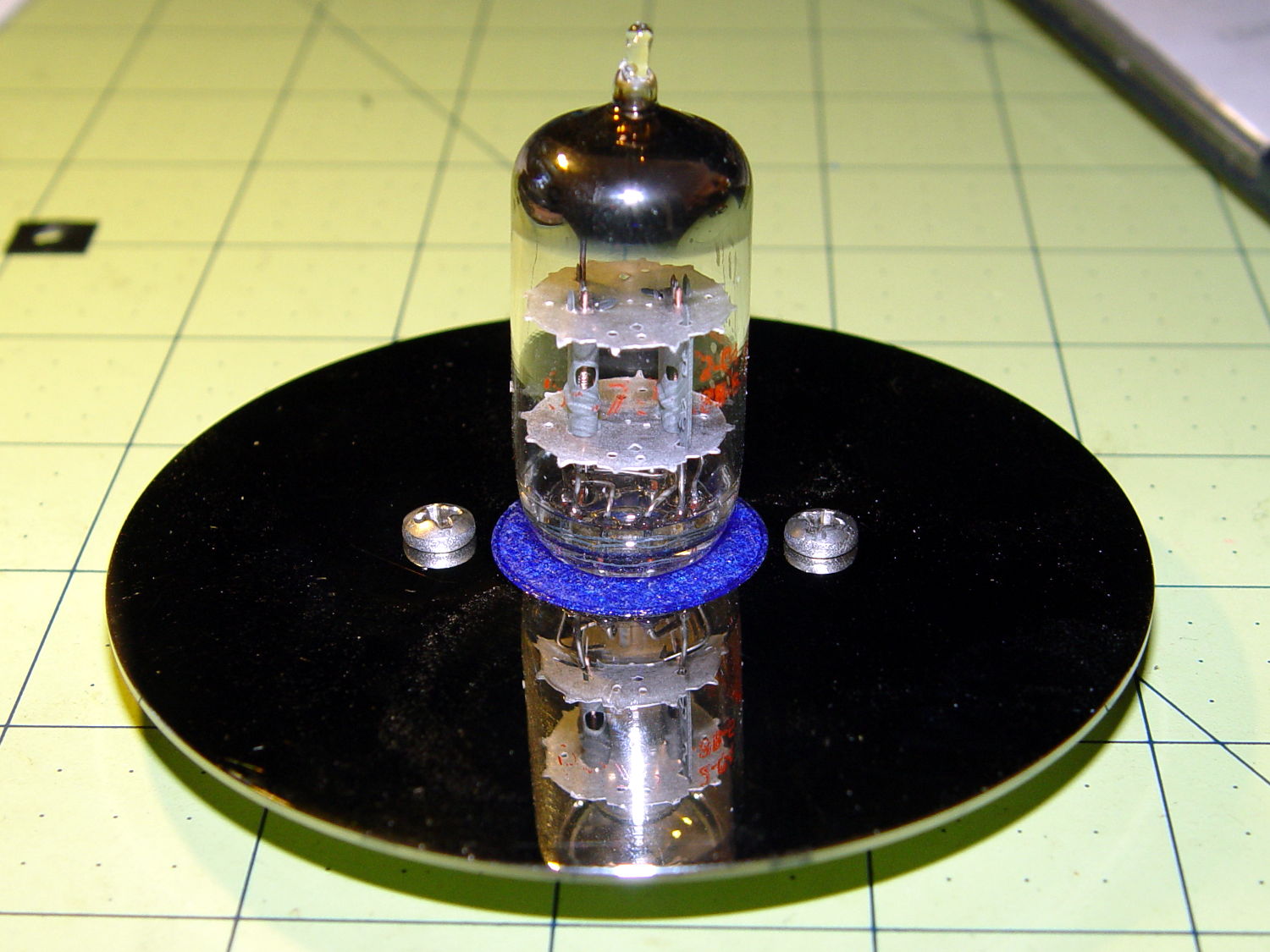
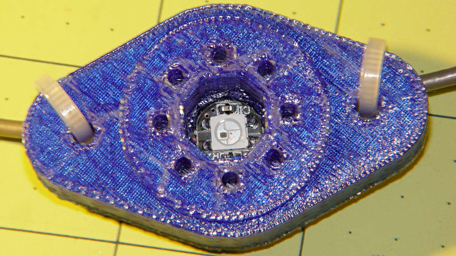
Pixel = [7.0,10.0,3.0]; // ID = contact patch, OD = PCB dia, LENGTH = overall thickness |
|
|
|
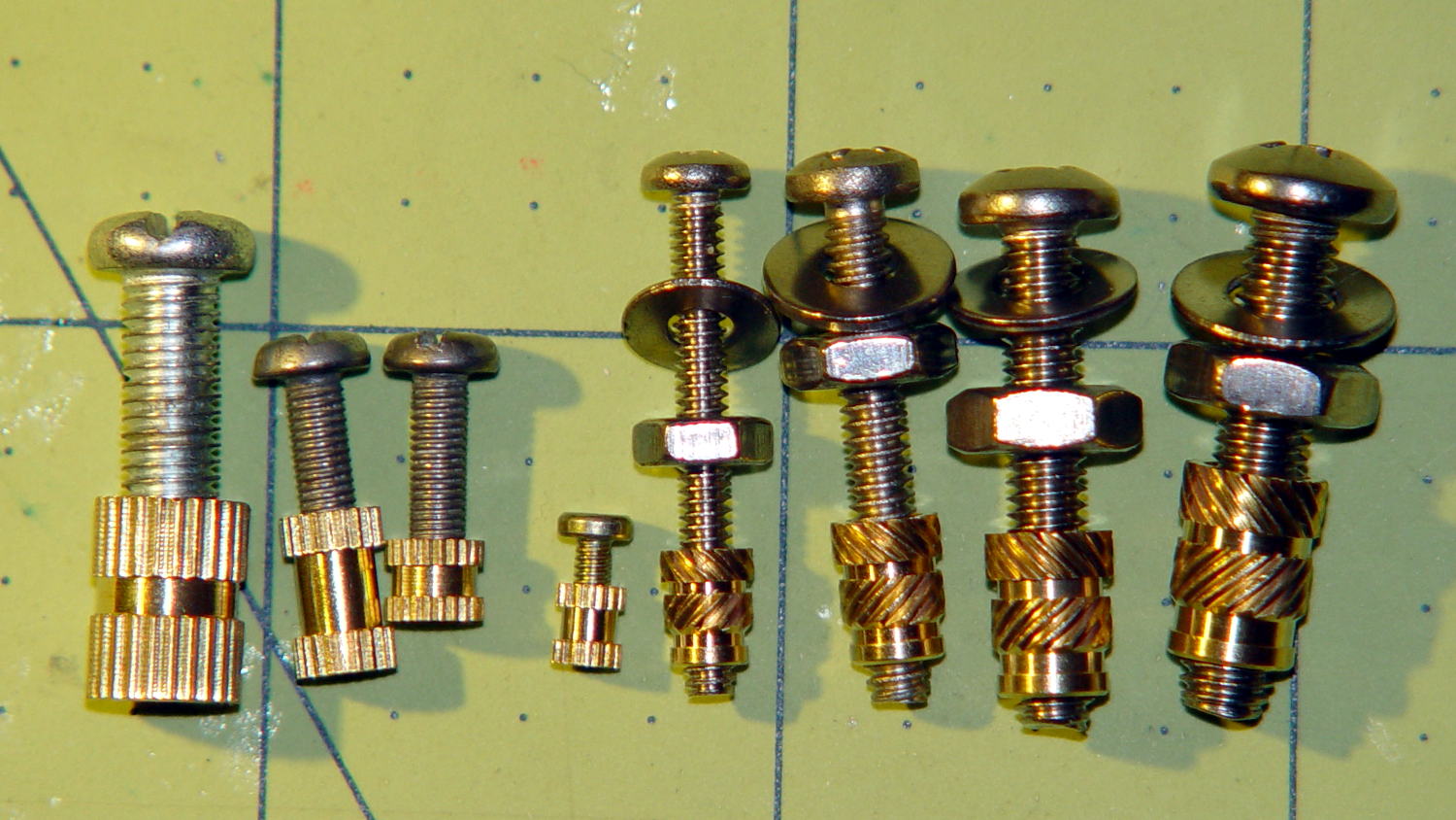
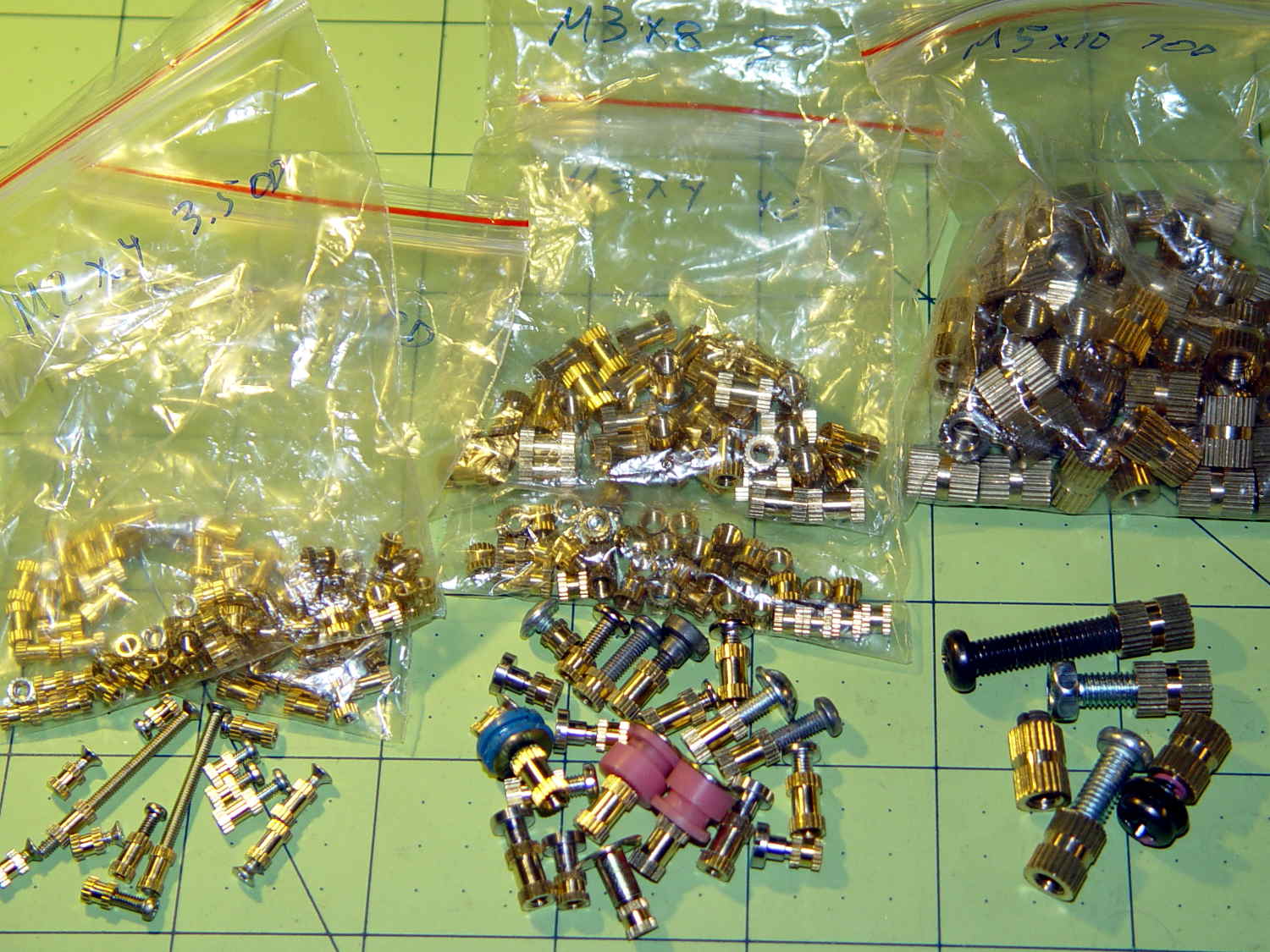
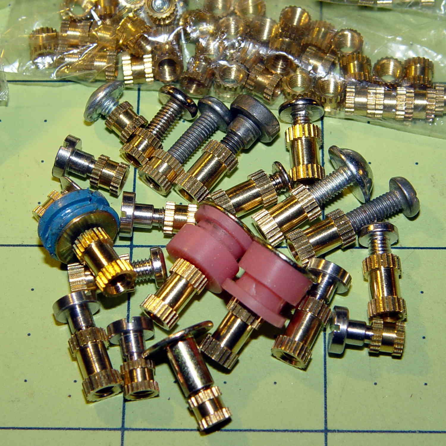
Nut = [3.5,5.2,7.2]; // socket mounting nut recess — threaded insert |
|
NutSides = 8; |
|
|
|
BaseShim = 2*ThreadThick; // between pin holes and pixel top |
|
SocketFlange = 2.0; // rim around socket below punchout |
|
PanelThick = 1.5; // socket extension through punchout |
|
|
|
FinCutterOD = 1/8 * inch; |
|
FinCapSize = [(Pixel[OD] + 2*FinCutterOD),30.0,(10.0 + 2*Pixel[LENGTH])]; |
|
|
|
|
|
//———————- |
|
// Useful routines |
|
|
|
module PolyCyl(Dia,Height,ForceSides=0) { // based on nophead's polyholes |
|
|
|
Sides = (ForceSides != 0) ? ForceSides : (ceil(Dia) + 2); |
|
|
|
FixDia = Dia / cos(180/Sides); |
|
|
|
cylinder(r=(FixDia + HoleWindage)/2,h=Height,$fn=Sides); |
|
} |
|
|
|
//———————- |
|
// Tube cap |
|
|
|
CapTube = [4.0,3/16 * inch,10.0]; // brass tube for flying lead to cap LED |
|
|
|
CapSize = [Pixel[ID],(Pixel[OD] + 3.0),(CapTube[OD] + 2*Pixel[LENGTH])]; |
|
|
|
CapSides = 6*4; |
|
|
|
module Cap() { |
|
|
|
difference() { |
|
union() { |
|
cylinder(d=CapSize[OD],h=(CapSize[LENGTH]),$fn=CapSides); // main cap body |
|
translate([0,0,CapSize[LENGTH]]) // rounded top |
|
scale([1.0,1.0,0.65]) |
|
sphere(d=CapSize[OD]/cos(180/CapSides),$fn=CapSides); // cos() fixes slight undersize vs cylinder |
|
cylinder(d1=(CapSize[OD] + 2*3*ThreadWidth),d2=CapSize[OD],h=1.5*Pixel[LENGTH],$fn=CapSides); // skirt |
|
} |
|
|
|
translate([0,0,-Protrusion]) // bore for wiring to LED |
|
PolyCyl(CapSize[ID],(CapSize[LENGTH] + 3*ThreadThick + Protrusion),CapSides); |
|
|
|
translate([0,0,-Protrusion]) // PCB recess with clearance for tube dome |
|
PolyCyl(Pixel[OD],(1.5*Pixel[LENGTH] + Protrusion),CapSides); |
|
|
|
translate([0,0,(1.5*Pixel[LENGTH] – Protrusion)]) // small step + cone to retain PCB |
|
cylinder(d1=(Pixel[OD]/cos(180/CapSides)),d2=Pixel[ID],h=(Pixel[LENGTH] + Protrusion),$fn=CapSides); |
|
|
|
translate([0,0,(CapSize[LENGTH] – CapTube[OD]/(2*cos(180/8)))]) // hole for brass tube holding wire loom |
|
rotate([90,0,0]) rotate(180/8) |
|
PolyCyl(CapTube[OD],CapSize[OD],8); |
|
} |
|
|
|
} |
|
|
|
//———————- |
|
// Heatsink tube cap |
|
|
|
|
|
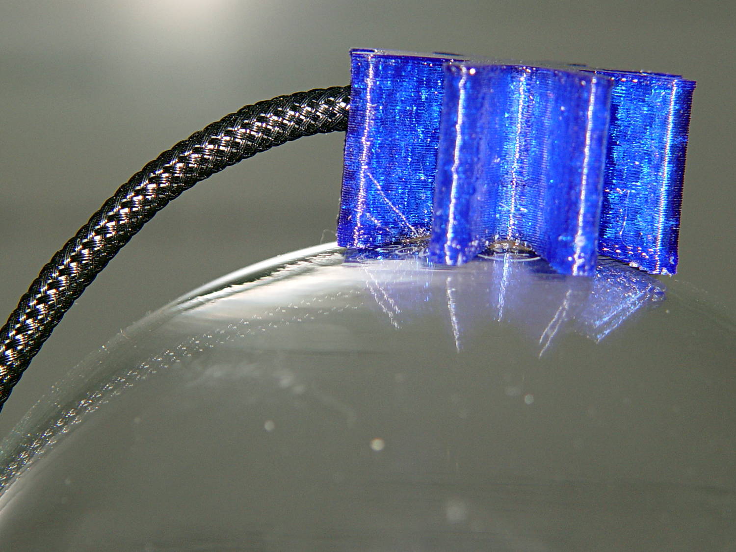
module FinCap() { |
|
|
|
CableOD = 3.5; // cable + braid diameter |
|
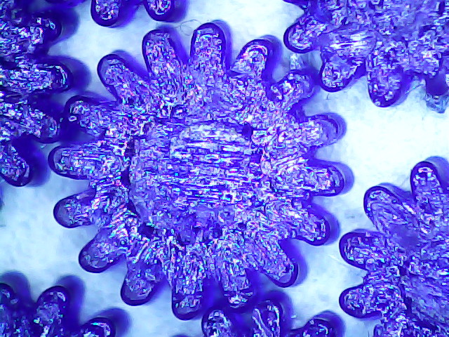
BulbOD = 3.75 * inch; // bulb OD; use 10 inches for flat |
|
|
|
echo(str("Fin Cutter: ",FinCutterOD)); |
|
FinSides = 2*4; |
|
|
|
BulbRadius = BulbOD / 2; |
|
BulbDepth = BulbRadius – sqrt(pow(BulbRadius,2) – pow(FinCapSize[OD],2)/4); |
|
echo(str("Bulb OD: ",BulbOD," recess: ",BulbDepth)); |
|
|
|
NumFins = floor(PI*FinCapSize[ID] / (2*FinCutterOD)); |
|
FinAngle = 360 / NumFins; |
|
echo(str("NumFins: ",NumFins," angle: ",FinAngle," deg")); |
|
|
|
difference() { |
|
union() { |
|
cylinder(d=FinCapSize[ID],h=FinCapSize[LENGTH],$fn=2*NumFins); // main body |
|
|
|
for (i = [0:NumFins – 1]) // fins |
|
rotate(i * FinAngle) |
|
hull() { |
|
translate([FinCapSize[ID]/2,0,0]) |
|
rotate(180/FinSides) |
|
cylinder(d=FinCutterOD,h=FinCapSize[LENGTH],$fn=FinSides); |
|
translate([(FinCapSize[OD] – FinCutterOD)/2,0,0]) |
|
rotate(180/FinSides) |
|
cylinder(d=FinCutterOD,h=FinCapSize[LENGTH],$fn=FinSides); |
|
} |
|
|
|
rotate(FinAngle/2) // cable entry boss |
|
translate([FinCapSize[ID]/2,0,FinCapSize[LENGTH]/2]) |
|
cube([FinCapSize[OD]/4,FinCapSize[OD]/4,FinCapSize[LENGTH]],center=true); |
|
} |
|
|
|
for (i = [1:NumFins – 1]) // fin inner gullets, omit cable entry side |
|
rotate(i * FinAngle + FinAngle/2) // joint isn't quite perfect, but OK |
|
translate([FinCapSize[ID]/2,0,-Protrusion]) |
|
rotate(0*180/FinSides) |
|
cylinder(d=FinCutterOD/cos(180/FinSides),h=(FinCapSize[LENGTH] + 2*Protrusion),$fn=FinSides); |
|
|
|
translate([0,0,-Protrusion]) // PCB recess |
|
PolyCyl(Pixel[OD],(1.5*Pixel[LENGTH] + Protrusion),FinSides); |
|
|
|
PolyCyl(Pixel[ID],(FinCapSize[LENGTH] – 3*ThreadThick),FinSides); // bore for LED wiring |
|
|
|
translate([0,0,(FinCapSize[LENGTH] – 3*ThreadThick – 2*CableOD/(2*cos(180/8)))]) // cable inlet |
|
rotate(FinAngle/2) rotate([0,90,0]) rotate(180/8) |
|
PolyCyl(CableOD,FinCapSize[OD],8); |
|
|
|
if (BulbOD <= 10.0 * inch) // curve for top of bulb |
|
translate([0,0,-(BulbRadius – BulbDepth + 2*ThreadThick)]) // … slightly flatten tips |
|
sphere(d=BulbOD,$fn=16*FinSides); |
|
} |
|
|
|
} |
|
|
|
|
|
//———————- |
|
// Aperture for USB-to-serial adapter snout |
|
// These are all magic numbers, of course |
|
|
|
module USBPort() { |
|
|
|
translate([0,28.0]) |
|
rotate([90,0,0]) |
|
linear_extrude(height=28.0) |
|
polygon(points=[ |
|
[0,0], |
|
[8.0,0], |
|
[8.0,4.0], |
|
// [4.0,4.0], |
|
[4.0,6.5], |
|
[-4.0,6.5], |
|
// [-4.0,4.0], |
|
[-8.0,4.0], |
|
[-8.0,0], |
|
]); |
|
} |
|
|
|
|
|
//———————- |
|
// Box for Leviton ceramic lamp base |
|
|
|
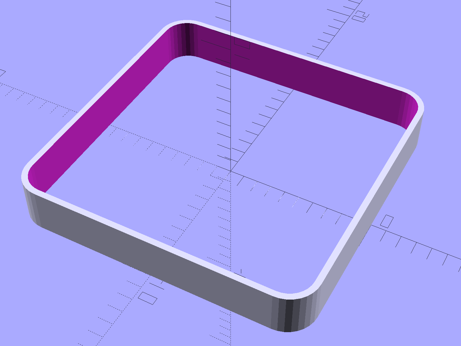
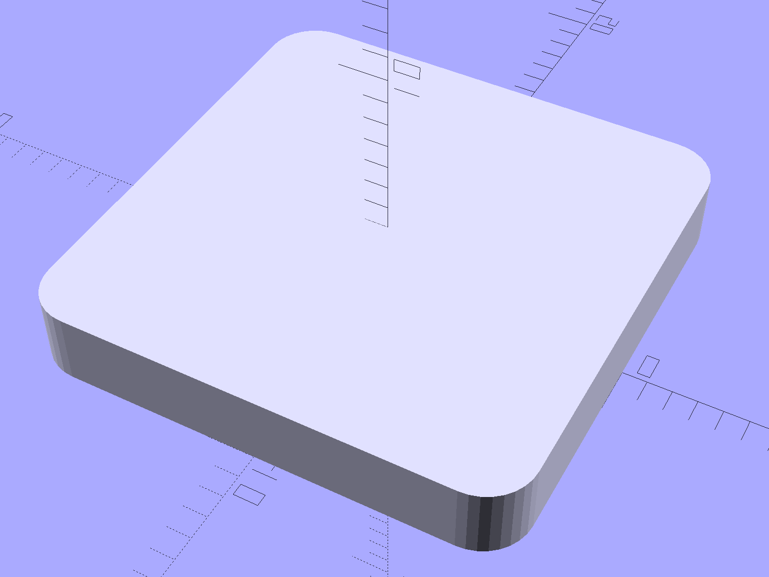
module LampBase() { |
|
|
|
Bottom = 3.0; |
|
Base = [4.0*inch,4.5*inch,20.0 + Bottom]; |
|
Sides = 12*4; |
|
|
|
Retainer = [3.5,11.0,1.0]; // flat fiber washer holding lamp base screws in place |
|
|
|
StudSides = 8; |
|
StudOC = 3.5 * inch; |
|
Stud = [Nut[OD], // 6-32 tapped brass insert |
|
min(15.0,1.5*(Base[ID] – StudOC)/cos(180/StudSides)), // OD = big enough to merge with walls |
|
(Base[LENGTH] – Retainer[LENGTH])]; // leave room for retainer |
|
|
|
|
|
union() { |
|
difference() { |
|
rotate(180/Sides) |
|
cylinder(d=Base[OD],h=Base[LENGTH],$fn=Sides); |
|
rotate(180/Sides) |
|
translate([0,0,Bottom]) |
|
cylinder(d=Base[ID],h=Base[LENGTH],$fn=Sides); |
|
translate([0,-Base[OD]/2,Bottom + 1.2]) // mount on double-sided foam tape |
|
rotate(0) |
|
USBPort(); |
|
} |
|
for (i = [-1,1]) |
|
translate([i*StudOC/2,0,0]) |
|
rotate(180/StudSides) |
|
difference() { |
|
cylinder(d=Stud[OD],h=Stud[LENGTH],$fn=StudSides); |
|
translate([0,0,Bottom]) |
|
PolyCyl(Stud[ID],(Stud[LENGTH] – (Bottom – Protrusion)),6); |
|
} |
|
} |
|
} |
|
|
|
//———————- |
|
// Tube Socket |
|
|
|
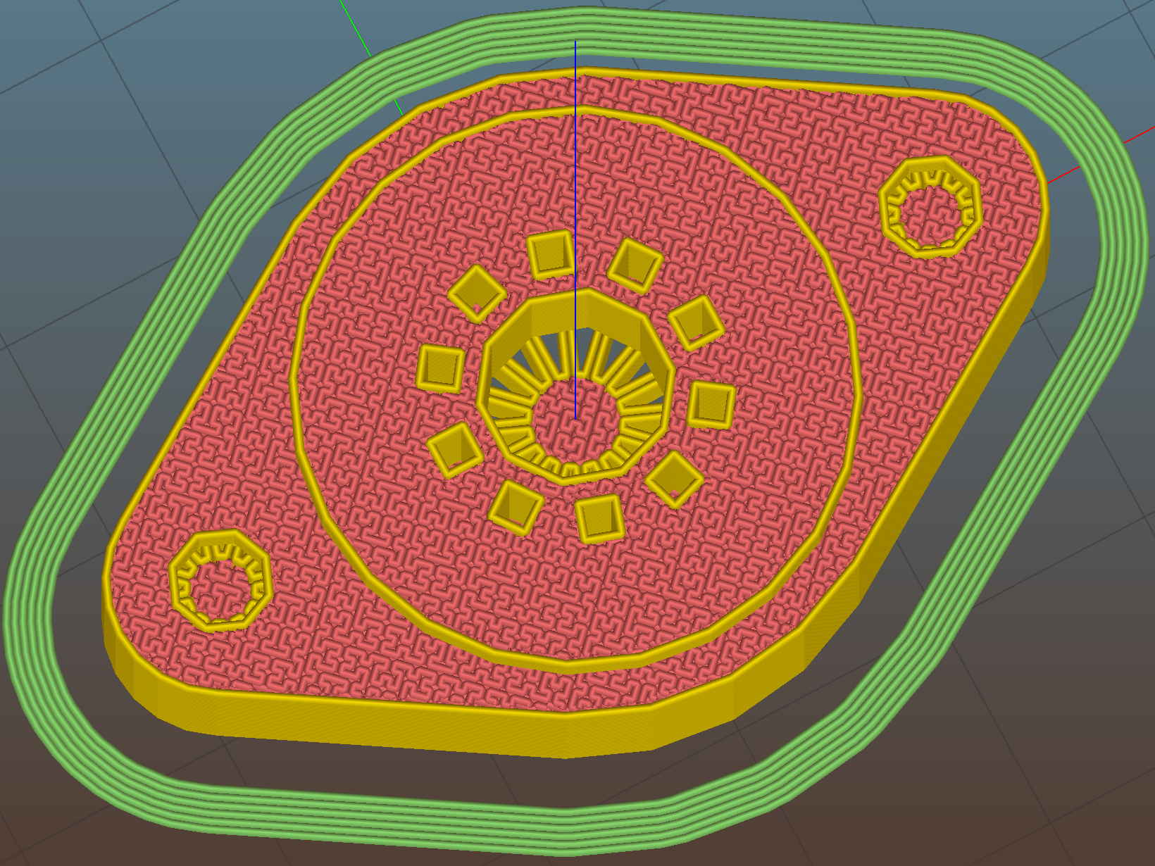
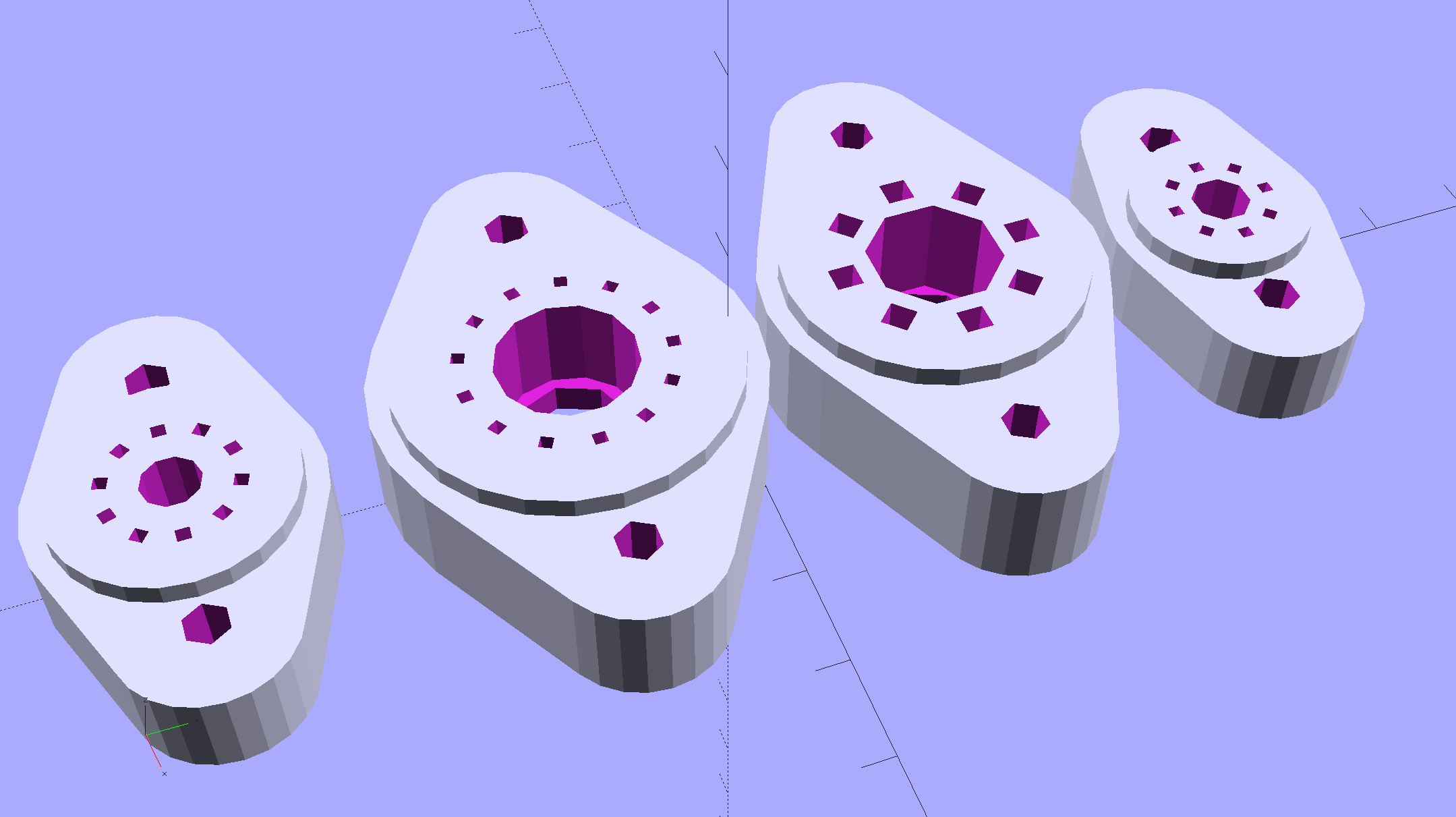
module Socket(Name = DefaultSocket) { |
|
|
|
NumSides = 6*4; |
|
|
|
Tube = search([Name],TubeData,1,0)[0]; |
|
echo(str("Building ",TubeData[Tube][0]," socket")); |
|
echo(str(" Punch: ",TubeData[ID][T_PUNCHOD]," mm = ",TubeData[ID][T_PUNCHOD]/inch," inch")); |
|
echo(str(" Screws: ",TubeData[ID][T_SCREWOC]," mm =",TubeData[ID][T_SCREWOC]/inch," inch OC")); |
|
|
|
OAH = Pixel[LENGTH] + BaseShim + TubeData[Tube][T_PINLEN]; |
|
BaseHeight = OAH – PanelThick; |
|
|
|
difference() { |
|
union() { |
|
linear_extrude(height=BaseHeight) |
|
hull() { |
|
circle(d=(TubeData[Tube][T_PUNCHOD] + 2*SocketFlange),$fn=NumSides); |
|
for (i=[-1,1]) |
|
translate([i*TubeData[Tube][T_SCREWOC]/2,0]) |
|
circle(d=2.0*Nut[OD],$fn=NumSides); |
|
} |
|
cylinder(d=TubeData[Tube][T_PUNCHOD],h=OAH,$fn=NumSides); // boss in chassis punch hole |
|
} |
|
|
|
for (i=[0:(TubeData[Tube][T_NUMPINS] – 1)]) // tube pins |
|
rotate(i*360/TubeData[Tube][T_NUMPINS]) |
|
translate([TubeData[Tube][T_PINBCD]/2,0,(OAH – TubeData[Tube][T_PINLEN])]) |
|
rotate(180/4) |
|
PolyCyl(TubeData[Tube][T_PINOD],(TubeData[Tube][T_PINLEN] + Protrusion),4); |
|
|
|
for (i=[-1,1]) // mounting screw holes & nut traps / threaded inserts |
|
translate([i*TubeData[Tube][T_SCREWOC]/2,0,-Protrusion]) { |
|
PolyCyl(Nut[OD],(Nut[LENGTH] + Protrusion),NutSides); |
|
PolyCyl(Nut[ID],(OAH + 2*Protrusion),NutSides); |
|
} |
|
|
|
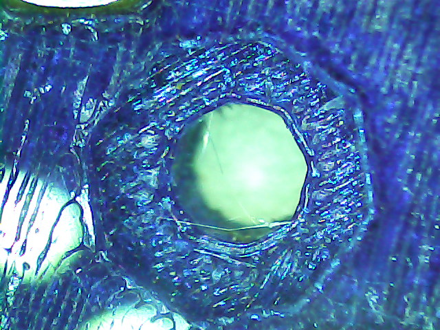
translate([0,0,-Protrusion]) { // LED recess |
|
PolyCyl(Pixel[OD],(Pixel[LENGTH] + Protrusion),8); |
|
} |
|
|
|
translate([0,0,(Pixel[LENGTH] – Protrusion)]) { // light pipe |
|
rotate(180/TubeData[Tube][T_NUMPINS]) |
|
PolyCyl(TubeData[Tube][T_PIPEOD],(OAH + 2*Protrusion),TubeData[Tube][T_NUMPINS]); |
|
} |
|
} |
|
|
|
// Totally ad-hoc support structures … |
|
|
|
if (Support) { |
|
color("Yellow") { |
|
for (i=[-1,1]) // nut traps |
|
translate([i*TubeData[Tube][T_SCREWOC]/2,0,(Nut[LENGTH] – ThreadThick)/2]) |
|
for (a=[0:5]) |
|
rotate(a*30 + 15) |
|
cube([2*ThreadWidth,0.9*Nut[OD],(Nut[LENGTH] – ThreadThick)],center=true); |
|
|
|
if (Pixel[OD] > TubeData[Tube][T_PIPEOD]) // support pipe only if needed |
|
translate([0,0,(Pixel[LENGTH] – ThreadThick)/2]) |
|
for (a=[0:7]) |
|
rotate(a*22.5) |
|
cube([2*ThreadWidth,0.9*Pixel[OD],(Pixel[LENGTH] – ThreadThick)],center=true); |
|
|
|
} |
|
} |
|
|
|
} |
|
|
|
//———————- |
|
// Build it |
|
|
|
if (Layout == "Cap") { |
|
if (Section) |
|
difference() { |
|
Cap(); |
|
translate([-CapSize[OD],0,CapSize[LENGTH]]) |
|
cube([2*CapSize[OD],2*CapSize[OD],3*CapSize[LENGTH]],center=true); |
|
} |
|
else |
|
Cap(); |
|
} |
|
|
|
if (Layout == "FinCap") { |
|
if (Section) render(convexity=5) |
|
difference() { |
|
FinCap(); |
|
// translate([0,-FinCapSize[OD],FinCapSize[LENGTH]]) |
|
// cube([2*FinCapSize[OD],2*FinCapSize[OD],3*FinCapSize[LENGTH]],center=true); |
|
translate([-FinCapSize[OD],0,FinCapSize[LENGTH]]) |
|
cube([2*FinCapSize[OD],2*FinCapSize[OD],3*FinCapSize[LENGTH]],center=true); |
|
} |
|
else |
|
FinCap(); |
|
} |
|
|
|
if (Layout == "BuildFinCap") |
|
translate([0,0,FinCapSize[LENGTH]]) |
|
rotate([180,0,0]) |
|
FinCap(); |
|
|
|
if (Layout == "LampBase") |
|
LampBase(); |
|
|
|
if (Layout == "USBPort") |
|
USBPort(); |
|
|
|
if (Layout == "Socket") |
|
if (Section) { |
|
difference() { |
|
Socket(); |
|
translate([-100/2,0,-Protrusion]) |
|
cube([100,50,50],center=false); |
|
} |
|
} |
|
else |
|
Socket(); |
|
|
|
if (Layout == "Sockets") { |
|
translate([0,50,0]) |
|
Socket("Mini7"); |
|
translate([0,20,0]) |
|
Socket("Octal"); |
|
translate([0,-15,0]) |
|
Socket("Duodecar"); |
|
translate([0,-50,0]) |
|
Socket("Noval"); |
|
} |