The Smell of Molten Projects in the Morning

Ed Nisley's Blog: Shop notes, electronics, firmware, machinery, 3D printing, laser cuttery, and curiosities. Contents: 100% human thinking, 0% AI slop.

Tag: CNC

Making parts with mathematics

  • Tour Easy Daytime Running Light: Flashlight Ball

    A flashlight used as a daytime running light must point generally forward and an actual bike headlight must light up the road, so it must sit on an az-el mount. My old bike helmet mirror mount had actual vertical and horizontal joints:

    Helmet mirror mount - El slide in place
    Helmet mirror mount – El slide in place

    Every doodle along those lines seemed too big, too fragile, too fiddly, or all at once.

    Living here in the future, though, we can produce (crude) ball joints to order:
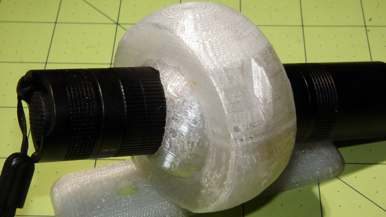
    Flashlight Ball Mount
    Flashlight Ball Mount

    That’s an early version of the outer mount using threaded brass inserts.

    The ball around the flashlight separates along the obvious plane of symmetry, with a 2 mm socket-head cap screw and brass insert on each side. I tried printing the hemispheres convex-side-up with hand-hewn support structures inside:
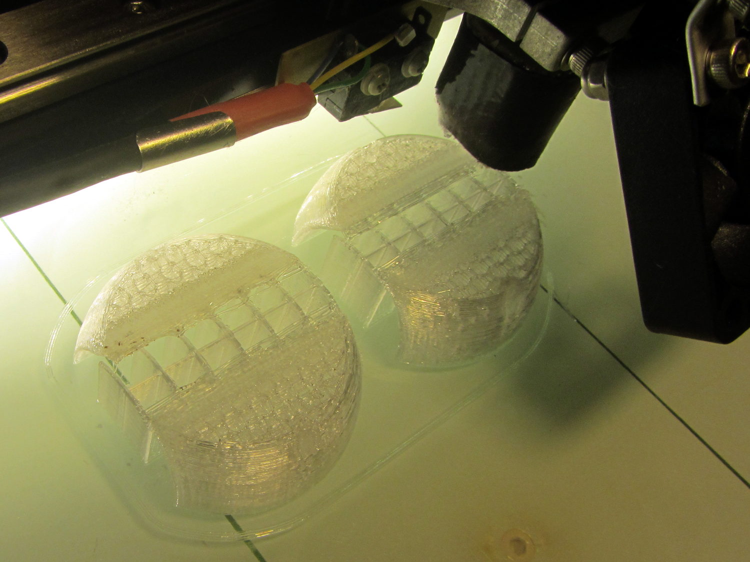
    Flashlight Ball Mount - support structure - on platform
    Flashlight Ball Mount – support structure – on platform

    The huge overhanging sections parallel to the axis didn’t bond to the supports, curled upward, and began nudging the dangling Z-axis homing switch actuator. This wasn’t a completely wasted effort, though, as similar support structures came in handy for the outer clamp ring.

    Flipping the hemispheres over so they printed U-channel upward didn’t work much better, even sitting on a flat section to eliminate the absurd part of the overhang. This view shows one hemisphere with the missing cap:
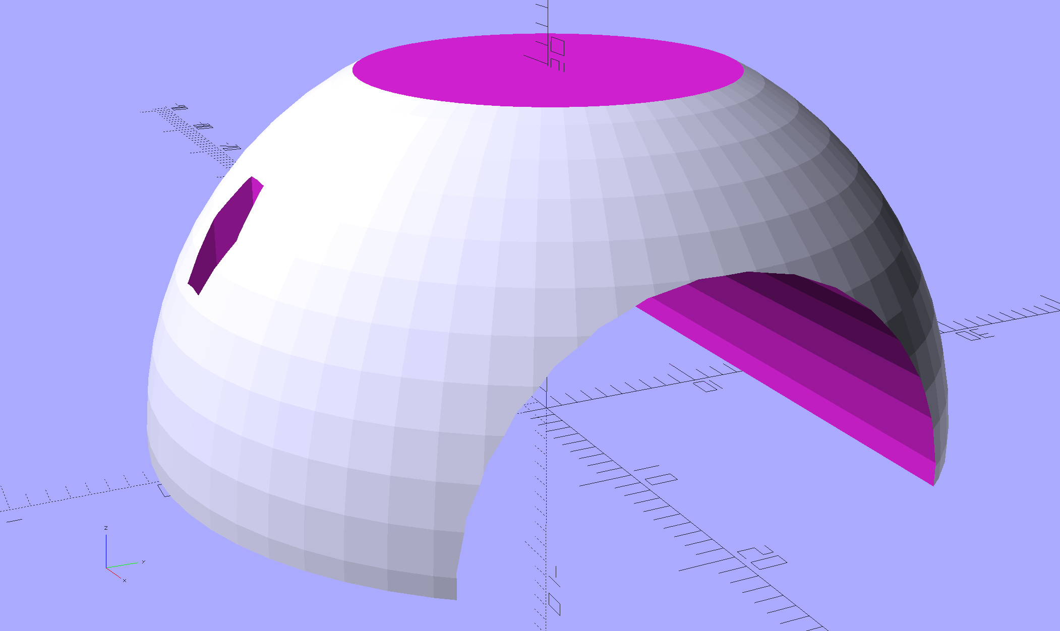
    Fairing Flashlight Mount - Ball - solid model
    Fairing Flashlight Mount – Ball – solid model

    Flipped over, the flat surface bonded perfectly to the platform, but the overhang still warped as the upper layers cooled and pulled the perimeter upward:

    Flashlight Ball Mount - warped section
    Flashlight Ball Mount – warped section

    Because normal support structures don’t contact the outer surface, I added fins to the model to hold the perimeter (almost) flat until the outer walls became sufficiently vertical to stop warping:
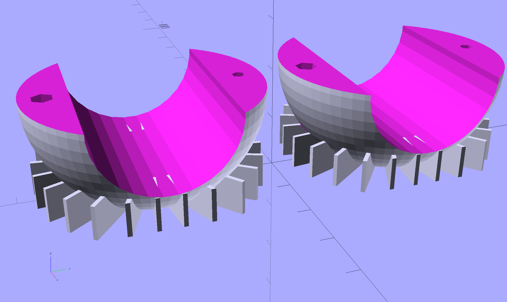
    Fairing Flashlight Mount - Ball - build view - solid model
    Fairing Flashlight Mount – Ball – build view – solid model

    They’re fearsome hedgehogs in person:
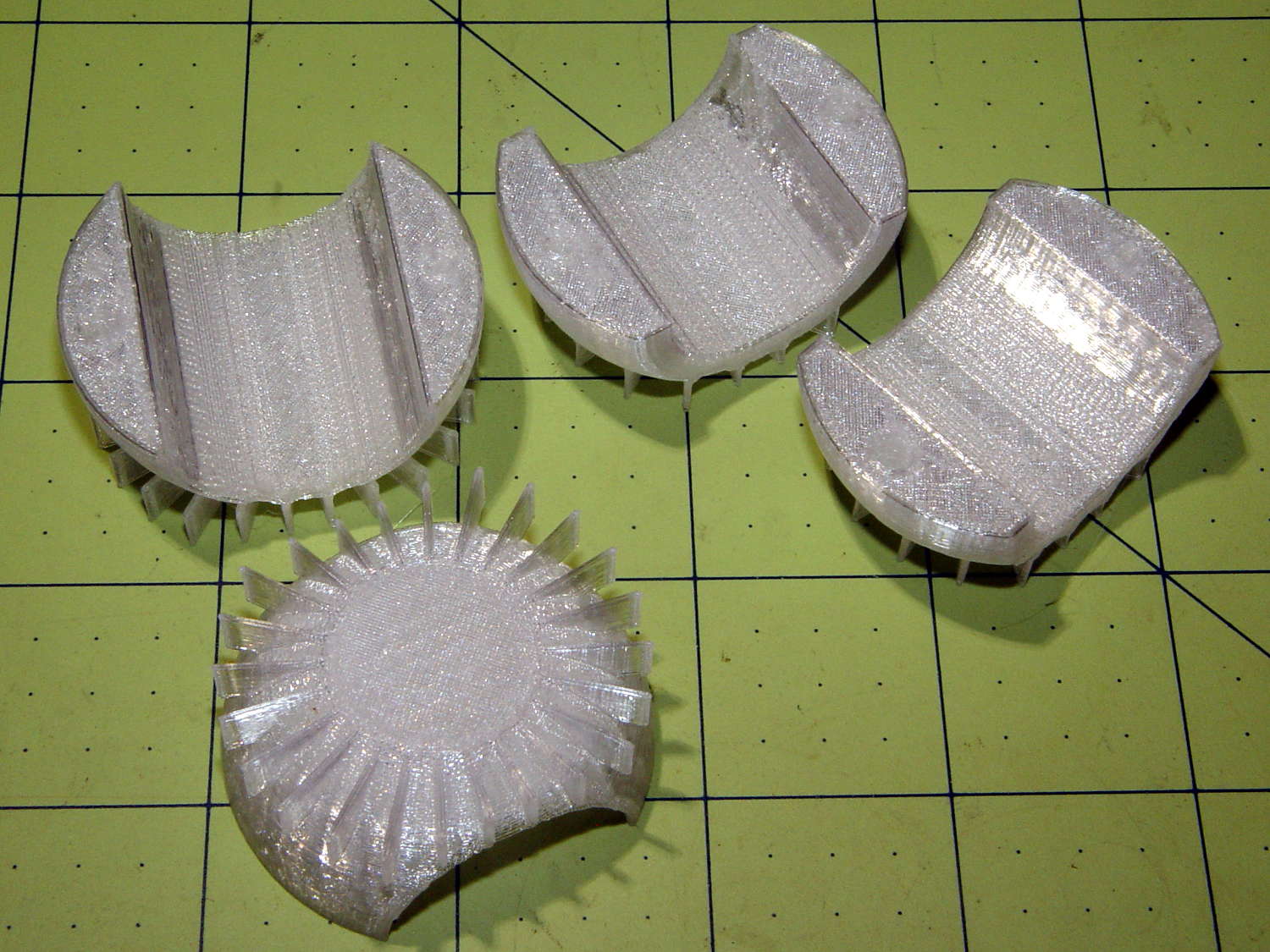
    Flashlight Ball Mount - flattening fins
    Flashlight Ball Mount – flattening fins

    The grip diameter determines the sphere diameter, as the sphere must have enough meat next to the grip to hold the screws and inserts. Rather than have the diameter different for every flashlight, I set it to the maximum of 45 mm or the actual diameter, which means all the flashlights in my collection have a common ball size. The hemispheres on the right have flattened ends to accommodate flashlight grips shorter than the sphere’s final diameter, achieved with a pair of intersection() operations lopping off the protruding bits:

    //- Ball around flashlight
    // Must print two!
    module BodyBall() {
    difference() {
    intersection() {
    sphere(d=BallOD,$fn=2*NumSides); // basic ball
    cube([BallLength,2*BallOD,2*BallOD],center=true); // max of flashlight grip length
    }
    translate([-LightBodies[FlashIndex][F_GRIPOD],0,0])
    rotate([0,90,0]) rotate(180/NumSides)
    PolyCyl(LightBodies[FlashIndex][F_GRIPOD],2*BallOD,NumSides); // flashlight body
    for (j=[-1,1])
    translate([0,j*BallScrewOC/2,0]) // commmon screw offset
    translate([0,0,-BallOD])
    PolyCyl(BallInsert[ID],2*BallOD,6); // punch screw shaft through everything
    translate([0,BallScrewOC/2,-Protrusion])
    PolyCyl(BallInsert[OD],(BallInsert[LENGTH] + 3*ThreadThick + Protrusion),6); // threaded insert
    translate([0,-BallScrewOC/2,BallThick])
    PolyCyl(BallScrew[OD],BallOD,6); // screw head clearance
    translate([0,0,-BallOD/2]) // remove bottom half
    cube(BallOD,center=true);
    translate([0,0,BallOD – BallThick/2]) // slice off top = bottom for E-Z build
    cube(BallOD,center=true);
    }
    if (Support) {
    NumRibs = 24;
    RibHeight = (BallOD – LightBodies[FlashIndex][F_GRIPOD]/cos(180/NumSides) – BallThick) / 2;
    ChordC = 2*sqrt(BallThick*BallOD/2 – pow(BallThick/2,2));
    intersection() {
    cube([BallLength,2*BallOD,2*BallOD],center=true); // max of flashlight grip length
    translate([0,0,BallOD/2 – BallThick/2])
    for (i=[0:NumRibs – 1])
    rotate(i*360/NumRibs + 180/NumRibs) // avoid screw holes
    translate([ChordC/2 + BallOD/8,0,-RibHeight/2])
    cube([BallOD/4,2*ThreadWidth,RibHeight],center=true);
    }
    }
    }

    Because the fins extend from resolutely convex surfaces, I snipped them off with flush-cutting pliers, reamed out the holes, epoxied the inserts in place, assembled the ball, and introduced it to Mr Belt Sander.

    Protip: don’t hold the ball with your finger through the hole. It will eventually fly off under the workbench and it’s better if it doesn’t break your finger in the process.

    A somewhat rough outer surface turns out to be an advantage, not a liability, as the clamp ring around the ball must hold it against the normal (and unusually severe) vibrations found on a bike.

    The inner cylindrical section is smooth enough to require a wrap of tape around the flashlight grip to anchor it in position. The tape adheres to the flashlight and squishes into the ball’s layer lines, even under mild pressure from the 2 mm screws. The outer clamp ring applies compression to the ball, so the tiny screws need not withstand much force at all, which is a good thing.

  • HP 7475A Plotter: Pen Carousel Geneva Drive

    A note arrived from someone who obviously couldn’t pass up an orphaned HP 7475A plotter:

    The plotter I received works beautifully, except that the carousel doesn’t rotate. I found a YouTube video showing a 7475a running with the cover off, and there’s a little plastic piece – it looks like a teardrop – that advances the carousel, and is apparently part of the carousel motor assembly. Mine is missing that piece …

    The keyword is Geneva drive, a wonderfully simple technique to convert one rotation of the stepper motor into 1/6 turn of the pen carousel, with no need for fancy sensors.

    The (unofficial) HP Computer Museum has All The HP 7475A Documents and the Plotter Service Manual shows All The Parts. And, of course, I’ve written a bit about my adventures with an old 7475A.

    Back in the day, you could get the entire Pen Carousel Housing Assembly w/ Motor (PN 07475-60175) as a unit and the Carousel Motor Only (PN 3140-0687) as a separate thing, but not the Geneva drive wheel:

    HP7475A Carousel - Geneva drive cam
    HP7475A Carousel – Geneva drive cam

    The cam’s drive wheel end (in inches, because early 1980s):

    • 0.25 thick overall
    • 0.10 thick plate under pin end
    • 1.09 OD – rounded end

    The pin sticking up from the cam:

    • 0.154 OD (or fit to slot?)
    • 0.16 tall (above base plate)

    I have no good (i.e., easy + accurate) way to measure the distance from the motor shaft to the pin, but I doubt it’s critical. As long as the pin doesn’t quite whack the hub end of the slot, it’s all good:

    HP7475A Carousel - cam driving
    HP7475A Carousel – cam driving

    The 0.10 plate + 0.16 pin height don’t quite add up to the 0.25 overall measurement, but that’s certainly measurement error. I’d round the pin length downward and carve the drive from a 1/4 inch sheet.

    A 3D printed part would probably work, apart from the accuracy required to fit the D-shaped motor shaft. Perhaps a round hole, reamed to fit the shaft, carefully aligned / positioned, with epoxy filling the D-shaped void, would suffice. A dent in the round hole would give the epoxy something to grab.

    I’d be sorely tempted to use an actual metal / plastic rod for the pin, rather than depend on a stack of semi-fused plastic disks. The pin must withstand hitting the end of the “missing” slot during the power-on indexing rotation, because turning the carousel isn’t quite a non-contact sport. Normally, though, it enters the end of the slot without much fuss:

    HP7475A Carousel - cam engaging
    HP7475A Carousel – cam engaging

    The blocked slot sits at the bottom of that picture, with a small locating pin sticking upward just above the circular feature at the end of the arm: we’re seeing the negative of a plug inserted into the original injection mold.

    With a bit of luck, another HP 7475A plotter will fascinate everybody within hearing distance!

    [Update: It lives! ]

  • 3D Printer Design Conversation: Part 5

    The final installment of musings about building a large-format 3D printer …

    (Continued from yesterday)

    Perhaps they saw your blog post?

    The old-old (original) high-resistance Kysan motor costs something like $45 and, apart from minor cosmetic differences, looks /exactly/ the same as the old-new low-resistance motor. If you were picking motors and didn’t quite understand why you needed a low-resistance winding, which would you pick? Hence, my insistence on knowing the requirements before plunking down your money.

    To be fair, I didn’t understand that problem until the Thing-O-Matic rubbed my nose in it. With all four motors. Vigorously.

    So, yeah, I think I had a part in that.

    comes back to the same numbers over and over

    The new-new leadscrews have something like half the pitch of the old-new and old-old threads; I don’t recall the number offhand. In any event, that gives you twice the number of motor steps per millimeter of motion and roughly twice the lifting force. This is pretty much all good, even though it may reduce the maximum Z axis speed (depends on your settings & suchlike).

    When it moves upward by, say, 5 mm and downward by 5 mm, you’re measuring position repeatability. That level of repeatability is pretty much a given (for the M2, anyhow), but it doesn’t involve stiction & suchlike.

    Can you move the platform up by 0.01 mm, then down by 0.01 mm, and measure 0.01 mm change after each motion?

    Do larger increments track equally well in both directions?

    Move upward a few millimeters, then step downward by 0.01 mm per step. Does the measurement increase by 0.01 mm after each step?

    Repeat that by moving downward, then upward in 0.01 mm increments.

    If the platform moves without backlash & stiction in both directions with those increments, it’s a definite improvement.

    I wish I knew more
    everything you learned is burned into your head forever

    The way to learn more is exactly what you’re doing.

    Two things I learned a long time ago:

    1. Whenever you have two numbers, divide them and ask whether the ratio makes sense.

    2. Whenever you don’t understand a problem, do any part of it you do understand, then look at it again.

    Also, write everything down. When you come back later, you won’t remember quite how you got those results.

    Which is precisely why I have a blog. I search with Google (site:softsolder.com microstepping) and /wham/ I get a quick refresher on what I was thinking. That’s why I keep link-whoring URLs: that’s my memory out there!

    You’ll sometimes find scans of my scrawled notes & doodles. They won’t mean anything to you, but they remind me what I do to get the answers in that blog post.

    modern controllers utilize much higher voltage and current bursts

    More or less. Microstepping drivers apply a relatively high voltage, far in excess of what the winding can tolerate as a DC voltage, then regulate the current to a value that produces the appropriate waveform.

    This may be helpful:

    https://softsolder.com/2011/05/05/thing-o-matic-mbi-stepper-motor-analysis/

    The mass of the bed APPEARS to be cancelling out any magnetic or mechanical stiction.

    That can’t be true in both directions: the gravity vector points downward and the results aren’t symmetric. I think you’re reading noise. If the sequences of motions I described don’t produce the results I described, then you’re /definitely/ measuring noise.

    From back in the Thing-O-Matic days:

    https://softsolder.com/2011/05/22/thing-o-matic-z-axis-resolution-repeatability-backlash/

    E3D hot end setups vs MakerGear’s?

    No opinion.

    I’d want that groovemount post in an all-metal socket, though, rather than the traditional plastic, to get solid positioning and tolerance control. Makergear has the right idea with the aluminum V4 heater block mount.

  • 3D Printer Design Conversation: Part 4

    Continued musings about building a large-format 3D printer …

    (Continued from yesterday)

    taking your challenge and am starting by cloning the M2

    That gives you an existence theorem: you know exactly what you want to end up with.

    AFAICT, few of the M2’s parts bear standardized numbers you can simply order from a reputable seller. Makergear knows what it’s buying (obviously!), but they’re under no obligation to help out: you must reverse engineer the requirements, find a suitable part, find a supplier, then buy one item.

    Let me know how that works out for cost & performance; “cost” should include a nonzero value for your time and “performance” should have numbers you can verify. I (obviously) think the build will be a dead loss on both counts (*), but good data will be interesting.

    (*) Albeit useful for educational purposes, which I’ve used to justify many absurd projectst!

    How the heck do you read out the current (estimated, obviously) X Y Z position absolute to the machine coordinates?

    Perhaps M114 or M117?

    My overall list may be helpful, although the RepRap Marlin reference has more detail on their command set:

    https://softsolder.com/2013/03/14/g-code-and-m-code-grand-master-list/

    The LinuxCNC (and, perhaps, Machinekit) G-Code languages give you access to built-in variables and extend G-Code into a true scripting language. Marlin evolved differently and doesn’t support that sort of thing.

    G-Code is pretty much a write-only language, but you can do some interesting things:

    https://softsolder.com/2013/07/18/makergear-m2-cnc-platform-corner-clips/

    I use the gcmc compiler whenever I can for actual CNC machining:

    https://softsolder.com/2014/02/21/can-opener-gear-rebuild/

    Works for me, anyhow, although I don’t do much CNC these days.

    move my nozzle up .01 at a time

    Stiction / microstep errors / command resolution prevent that:

    Makergear M2 Z-axis Backlash Numbers

    The only way to measure the nozzle position is to measure a finished part with a known height, because any variation comes from the first layer offset. That’s if you have Z=0 at the platform, of course, rather than whatever offset you get by defining Z=0 at some random height based on jamming business cards / feeler gages / special Japanese rolling papers under the snout. [ptui & similar remarks]

    For example:

    https://softsolder.com/2015/09/14/makergear-m2-platform-stability/

    You need numbers. Lots of numbers. [grin]

    strip basic tools out of the control interface

    Yet another reason I don’t use S3D: that “Simplify” thing gets in the way of my obsessive need for control.

    (Continues tomorrow)

  • 3D Printer Design Conversation: Part 3

    More musings in response to questions about building a large-format 3D printer.

    (Continued from yesterday)

    make a direct clone of the M2. No thinking required.

    The present-day M2 has survived four years of rather fierce Darwininan winnowing, so it’s a much better thought-out product than, ahem, you may think just by looking at it.

    To build a one-off duplicate, you’ll spend as much money collecting the parts as you would to just buy another M2 and start printing.

    Should you buy cheap parts to save money, without considering the requirements, you’ll get, say, the same Z-axis motor Makergear used on the original M2, the complete faceplant of Thing-O-Matic electronics, or crap from eBay described as being kinda-sorta what you want.

    Sometimes crap from eBay can be educational, of course:

    https://softsolder.com/2013/01/24/hall-effect-sensors-from-ebay-variations-on-a-specification/

    I encourage thinking, particularly with numbers, because it leads to understanding, rather than being surprised by the results.

    increase the rigidity of the X and Y axis

    In round numbers, deflection varies as the fourth power of length: enlarge a frame member by 50% and it becomes five times bendier. If your design simply scales up the frame, it won’t hold the tolerances required to produce a good object.

    https://en.wikipedia.org/wiki/Euler%E2%80%93Bernoulli_beam_theory

    If you add more mass (“stiffening”) to the Y axis, then the Z axis motor (probably) can’t accelerate the new load upward with the original firmware settings and the Y axis motor may have trouble, too. Perhaps you should measure the as-built torque to support your design:

    https://softsolder.com/2013/07/02/makergear-m2-better-z-axis-motor-calculations/

    Reduce the acceleration and lower the print speed? Use bigger motors (if you can find a Z motor with the correct leadscrew) and lose vertical space? Make the frame taller and lose stiffness? Use two Z motors (like the RepRap Mendels) and get overconstrained vertical guides? Try building a kinematic slide and lose positioning accuracy? Your choice!

    If your intent is to print more parts at once, buy more M2 printers, which will not only be cheaper, but also give you more throughput, lower the cost of inevitable failures, good redundancy, and generally produce better results. Some of the folks on the forum run a dozen M2s building production parts; they’re not looking for bigger print volumes to wreck more parts at once.

    Conversely, if your intent is to learn how to build a printer, then, by all means, think about the design, run the numbers, collect the parts, then proceed. It sounds like a great project with plenty of opportunity for learning; don’t let me discourage you from proceeding!

    However, I’ll be singularly unhelpful with specific advice, because I’m not the guy building the printer. You must think carefully about what you want to achieve, figure out how to get there, and make it happen.

    To a large extent, searching my blog with appropriate keywords will tell you exactly what I think about 3D printing, generally with numbers to back up the conclusions. Get out your calculator, fire up your pencil, and get started!

    (Continues tomorrow)

  • 3D Printer Design Conversation: Part 2

    Wherein I continue dumping my responses to a large-format 3D printer project …

    (Continued from yesterday)

    What do you mean by 12 hour mean time to failure

    In round numbers, the cries of anguish on the M2 forum seem to increase as parts require more than a dozen hours from start to finish; while you can print things that require 48 hours, that’s not the way to bet. There are more ways for things to go wrong than for them to go right, given the rather rickety collection of software & firmware making everything happen, plus the gummy nature of squeezing hot plastic into precise heaps.

    Most of the time, it works fine.

    much cheaper hardened polished rod system that the taz 6 uses?

    Unless they’re doing something non-obvious to make a kinematic assembly, two rods on four hard mounts with four one-degree-of-freedom slides will be severely overconstrained and, I expect, a continuing hunk o’ trouble:

    https://softsolder.com/2011/02/04/thing-o-matic-x-and-z-axis-rod-alignment/

    FWIW, linear slides don’t eliminate the need for a rigid and well-aligned frame. Even the slab atop an M2 can deform by more than 0.1 mm under belt tension, which is enough to wreck the nozzle-to-platform alignment across the length of the X axis.

    “Arduino-class firmware (Marlin, et. al.) is a dead end” Why is that?

    Marlin is a dead end: they’re trying to jam hard real time motor control, soft real time command parsing, and non real time UI control into an 8 bit microcontroller teleported from the mid 90s. AVR microncontrollers worked really well up through the Cupcake and have held back printer design & performance ever since.

    Which inexpensive all in one board would you go with

    Machinekit on a Beaglebone seems to be the least awful of the current alternatives, but I haven’t examined the field recently enough to have a valid opinion. You’ll find plenty of proprietary “solutions” out there, none of which I’d be interested in.

    Am I wrong?

    I think so, but, then, I may be wrong, too. [grin]

    It’s incredibly easy to slap together a bunch of parts that look like they should become a 3D printer. It’s remarkably difficult to engineer a reliable, stable, accurate device that actually produces dependable results.

    Mooching design cues and parts from here & there doesn’t get you to the goal; if it did, Kickstarter wouldn’t be a graveyard of cheap 3D printer projects.

    design a very rigid system for cheap

    If it’s for your personal satisfaction, have at it, but a one-off large-format printer won’t be any cheaper than, say, a Taz 6. Some diligent searching will uncover any number of homebrew printer projects along the lines of what you’re considering; learning from their mistakes will certainly be edifying.

    Anything is possible, but if you want to end up with a state of the art machine, you must begin with numbers showing how & why it actually meets the requirements. 3D printing now operates at accuracies, speeds, and controls comparable to CNC machines, with corresponding structural demands. There’s a reason high-end CNC machines aren’t made of sheet metal and don’t use 8 bit microcontrollers.

    You might want to start at the beginning of my blog and read through my adventures with the Thing-O-Matic, which will explain why I’m such a curmudgeon …

    (Continues tomorrow)

  • 3D Printer Design Conversation: Part 1

    I recently engaged in a wide-ranging email exchange with a guy planning to scratch-build a large-format 3D printer. He figured it would be a straightforward exercise and asked for some advice; I may be more cynical that he expected.

    Over the next few days, I’ll dump my side of the conversation so I can refer to it in other contexts. I’ve left his side of the conversation as the short quotes that prompted my replies, but you can probably infer what he was thinking.

    He’s well-acquainted with CNC machining and recently added a Makergear M2 to his collection …

    I’m hooked.

    All of sudden, you realize what you’ve been missing!

    In round numbers, I’ve been designing & printing one “thing” every week for the last five years. Granted, my “things” look a lot like brackets, because they go into other shop projects, but 3D printing is how I make nearly all the shapes I formerly bashed from metal.

    I loves me my 3D printer!

    an open source design with AFFORDABLE, EASILY ACCESSIBLE parts with a build platform of at least 150% X/Y volume of the MakerGear

    Some years ago, I had the same general idea. Then I bought an M2 (replacing my Thing-O-Matic), considered LinuxCNC / Machinekit for motion control, and realized there wasn’t much point; I didn’t want to devote far too much time & effort to solving an already solved problem.

    A larger build volume doesn’t buy you as much as you think, while imposing far too many hard constraints. Basically, good-resolution extruders run at 2 to 10 mm³/s, so large objects require print times beyond the 12-hour MTTF of the “printing system”: something will go wrong often enough to drive you mad.

    Bonus: plastic’s thermal coefficient guarantees bed adhesion problems. Using high-traction materials (PEI / hairspray / whatever) introduces problems in the other direction. There’s a limit to how big you can make things before they either don’t stick or stick too hard.

    Some the fundamental design problems that nobody recognizes until far too late in their design:

    • nozzle-to-platform accuracy < ±0.05 mm
    • XY axis speeds 30 mm/s to 500 mm/s
    • Z axis stiction & backlash < 0.1 mm
    • filament drive with excellent retraction control / speed
    • bed adhesion vs. part removal vs. Z accuracy
    • Arduino-class firmware (Marlin, et. al.) is a dead end
    • Windows is crap in any part of a machine-control problem

    Those are hard requirements. At a minimum, your design must satisfy all of them: miss any one and you’re not in the game. It’s easy to build a cheap and crappy fused-filament 3D printer (see Kickstarter), but exceedingly difficult to build one at the state of the art (see patent litigation).

    The M2 descends from the original RepRap design, with the Y axis slinging far too much mass back & forth. That kills nozzle-to-platform accuracy, introduces temperature instability, and soaks up bench space. On the other paw, look at the problems Makerbot (not Makergear) had with their direct-drive extruder on an XY platform; getting that right requires nontrivial engineering

    Bowden filament drives have improved, but really can’t provide enough retraction control / speed. Delta printers always use Bowden drives, because they can’t sling a direct-drive extruder with enough XYZ speed & accuracy. Bowden on an XY platform has the worst of both worlds: bad retraction and difficult mechanical design.

    I think the M2 occupies a sweet spot in 3D printer design: excellent results without excessive complexity or expense. It’s not perfect, but good enough.

    But, then, I’m a known curmudgeon …

    (Continues tomorrow)