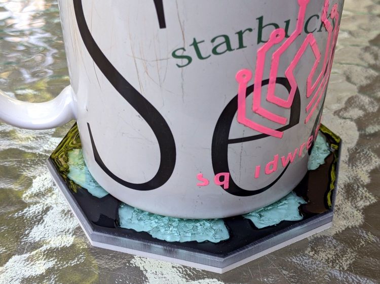
The proof of concept coaster might suffice for a shot glass, but my morning tea comes in a 20 ounce mug with a much larger footprint.
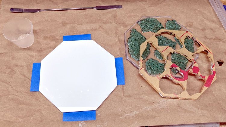
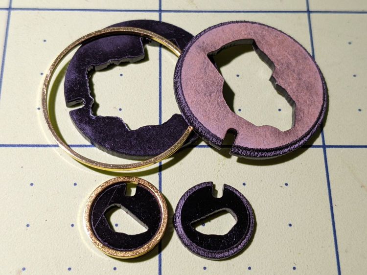
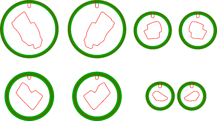
So, back to the Basement Shop, where a laser-cut and -engraved layout guide helps arrange and carry some suitable fragments:

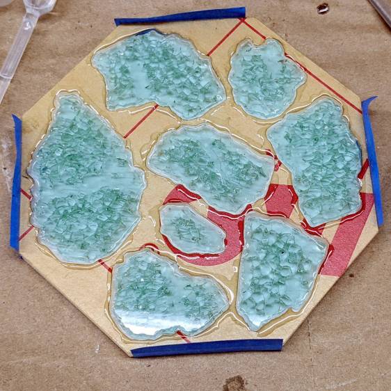
As before, scan the bottom of the fragments and wrap selections around them:

Apply the usual operations to get a suitable mask:

Fire the laser to cut the chipboard test template holding the fragments, then a white octagonal acrylic base plate and a transparent acrylic layer surrounding the fragments, and:
Mix up some pourable epoxy, smooth it over the base plate, squish the transparent layer atop it, use the tape (sticky side up) to hold the two layers in alignment, and gently insert the fragments:
I eased some epoxy around the perimeter of each fragment with a pipette in an attempt to reduce the glass-sliver hazard:
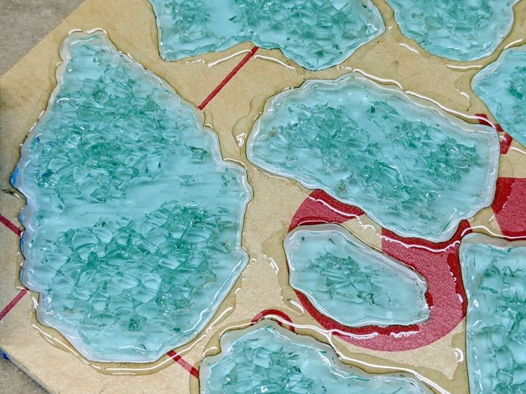
Yes, that’s on top of the protective paper, because then I can whisk the paper off to reveal the pristine surface around each fragment:

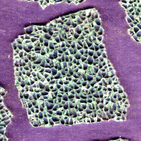
As with the smaller coaster, the epoxy penetrates the fractures and reduces the shattered appearance. Mary suggests tinted epoxy would produce an interesting effect and I’ll try that the next time around.
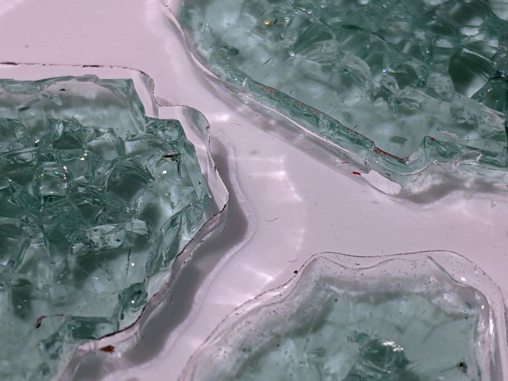
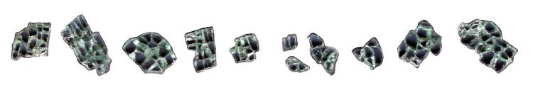
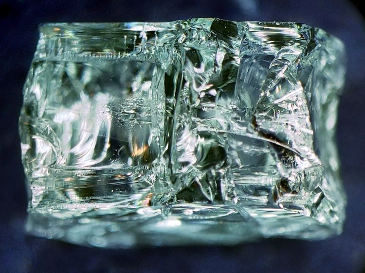
Because the smashed glass came from our neighbor’s lawn, it carried a bit of dirt and debris onto the playing field:
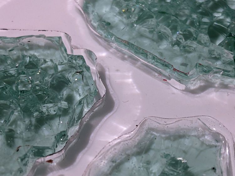
Seen through the edge of the coaster, the uneven surface of the epoxy fill around the fragments shows up clearly:

The top of the glass stands half a millimeter above the transparent acrylic. I knew that would happen and wanted to see how the bottom of the mug interacted with the epoxy-coated sides:

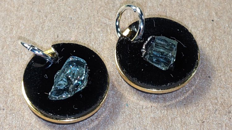
As it turned out, the epoxy coating wasn’t quite good enough to prevent tiny slivers from chipping off and, in the cold light of day, the pale-green-ish tinted glass didn’t stand out well against the white background.
So I taped up the perimeter, leveled the base, mixed up another batch of epoxy, added two drops of opaque black dye, and poured just enough to level the surface with the glass:

Introducing the meniscus to Mr Belt Sander put a bevel around the edge and finished it off well enough:
The Squidwrench logo looks a bit battered after three and a half years of trips through the dishwasher, although I didn’t expect it to last nearly this long.
There’s still a slight upward tilt around the perimeter, but it meets my simple requirements and the fragments definitely look better in black. The white base sets off the fragments, but a clear plate takes advantage of their transparency; a mirror sheet might be even more interesting.


